Table of Contents
Advertisement
Quick Links
Advertisement
Table of Contents

Related Manuals for Thrane&Thrane Capsat Messenger TT-3080A


Summary of Contents for Thrane&Thrane Capsat Messenger TT-3080A
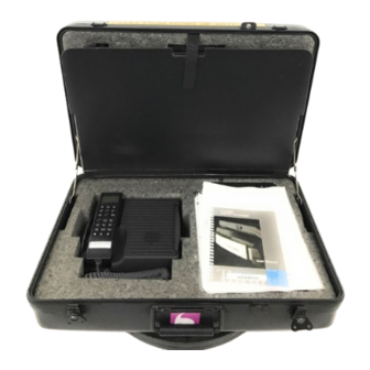
- Page 1 Capsat Messenger TT-3080A User Manual...
- Page 3 Thrane & Thrane Thrane & Thrane Thrane & Thrane Thrane & Thrane Capsat Messenger TT-3080A User Manual Copyright Thrane & Thrane A/S ALL RIGHTS RESERVED...
- Page 4 Information in this document is subject to change without notice and does not represent a commitment on the part of Thrane & Thrane A/S. © 2001 Thrane & Thrane A/S. All rights reserved. Printed in Denmark. Document Number TT98—111882-H. Release Date: 7 September 2001...
- Page 5 Safety Summary Safety Summary Safety Summary Safety Summary The following general safety precautions must be observed during all phases of operation, service and repair of this equipment. Failure to comply with these precautions or with specific warnings elsewhere in this manual violates safety standards of design, manufacture and intended use of the equipment.
- Page 6 This page is intentionally left blank...
-
Page 7: Table Of Contents
Table of Contents Table of Contents Table of Contents Table of Contents Table of Contents Introduction ................1-1 Description of the service ............2-1 The Capsat® Messenger............3-1 3.1 Hardware interfaces ............3-4 3.2 The handset ..............3-10 3.3 SIM card ................ 3-20 3.4 PCMCIA card.............. - Page 8 Table of Contents Table of Contents Table of Contents Table of Contents 6.7 Phone setup ..............6-11 6.7.1 Tel. numbers ............. 6-14 6.7.2 Route incoming..........6-16 6.7.3 Route outgoing ..........6-17 6.7.4 Security ............. 6-18 6.7.5 Sleep mode ............6-22 6.7.6 MMI setup............
- Page 9 Table of Contents Table of Contents Table of Contents Table of Contents This page is intentionally left blank 7-Sep-01 7-Sep-01 7-Sep-01 7-Sep-01 Page Page Page Page iii iii iii iii...
-
Page 11: Introduction
Hardware interfaces Hardware interfaces Hardware interfaces Hardware interfaces Introduction Introduction Introduction Introduction Introduction Congratulations purchasing your TT-3080A Capsat® Messenger. This terminal makes it possible for you to communicate from any country in the world using the Global Area Network service established Inmarsat. - Page 12 Introduction Introduction Introduction Introduction Hardware interfaces Hardware interfaces Hardware interfaces Hardware interfaces Chapter 10 Elevation and Azimuth 10 Elevation and Azimuth 10 Elevation and Azimuth 10 Elevation and Azimuth - enclosed maps to assist you with pointing the antenna. Please note that different software versions support different Please note that different software versions support different Please note that different software versions support different Please note that different software versions support different...
-
Page 13: Description Of The Service
Hardware interfaces Hardware interfaces Hardware interfaces Hardware interfaces Description of the service Description of the service Description of the service Description of the service Description of the service The Inmarsat Global Area Network service is based on 4 Geo- stationary satellites situated above the equator. Geo-stationary means that the satellites are always located in the same position, i.e. - Page 14 Description of the service Description of the service Description of the service Description of the service Hardware interfaces Hardware interfaces Hardware interfaces Hardware interfaces • High Speed Services (64 kbit/s) High Speed Services (64 kbit/s) High Speed Services (64 kbit/s) High Speed Services (64 kbit/s) •...
- Page 15 Hardware interfaces Hardware interfaces Hardware interfaces Hardware interfaces Description of the service Description of the service Description of the service Description of the service Important Notice: Important Notice: Important Notice: Important Notice: Before a terminal can be used on the network, it has to be commissioned by one of the Inmarsat Service Providers (ISP’s).
- Page 16 Description of the service Description of the service Description of the service Description of the service Hardware interfaces Hardware interfaces Hardware interfaces Hardware interfaces between faxes and modems with an analogue 2-wire interface. The 3.1 kHz audio service is transparent, and is suitable for all analogue applications including secure telephones.
-
Page 17: The Capsat® Messenger
Hardware interfaces Hardware interfaces Hardware interfaces Hardware interfaces The Capsat® Messenger The Capsat® Messenger The Capsat® Messenger The Capsat® Messenger The Capsat® Messenger The Capsat® Messenger System includes the following system components: • TT-3038A Capsat® Messenger Electronics Unit • TT-3620D Capsat® Messenger Handset •... - Page 18 The Capsat® Messenger The Capsat® Messenger The Capsat® Messenger The Capsat® Messenger Hardware interfaces Hardware interfaces Hardware interfaces Hardware interfaces Before using the terminal, it is necessary to unpack and connect the handset to the electronic unit. The handset connects at the bottom of the electronic unit.
- Page 19 Hardware interfaces Hardware interfaces Hardware interfaces Hardware interfaces The Capsat® Messenger The Capsat® Messenger The Capsat® Messenger The Capsat® Messenger The TT-3008A Antenna, connected at the rear, radiates micro wave signals during a call with the strongest radiated signal in front of the antenna (on the focal line) and drops off fairly quickly.
-
Page 20: Hardware Interfaces
The Capsat® Messenger The Capsat® Messenger The Capsat® Messenger The Capsat® Messenger Hardware interfaces Hardware interfaces Hardware interfaces Hardware interfaces Hardware interfaces The Electronic Unit of the Capsat® Messenger has the following hardware interfaces: • Handset • Analogue 2-wire RJ11 number 1 •... - Page 21 Hardware interfaces Hardware interfaces Hardware interfaces Hardware interfaces The Capsat® Messenger The Capsat® Messenger The Capsat® Messenger The Capsat® Messenger The handset may also be used as dial pad for devices connected to the terminal, that do not have a key pad to enter the phone number.
- Page 22 The Capsat® Messenger The Capsat® Messenger The Capsat® Messenger The Capsat® Messenger Hardware interfaces Hardware interfaces Hardware interfaces Hardware interfaces This interface can be used for connection of ISDN equipment – data as well as voice/picture based equipment (phones, audio codecs or video conferencing equipment).
- Page 23 Hardware interfaces Hardware interfaces Hardware interfaces Hardware interfaces The Capsat® Messenger The Capsat® Messenger The Capsat® Messenger The Capsat® Messenger RS-232 interface: RS-232 interface: RS-232 interface: RS-232 interface: The RS-232 port is a standard 9 pin serial port, the maximum port speed is 115.2 kbps.
- Page 24 The Capsat® Messenger The Capsat® Messenger The Capsat® Messenger The Capsat® Messenger Hardware interfaces Hardware interfaces Hardware interfaces Hardware interfaces USB - the Universal Serial Bus – shown above is a popular technology that allows a single universal plug to connect PCs and peripherals of all kinds to each other.
- Page 25 Hardware interfaces Hardware interfaces Hardware interfaces Hardware interfaces The Capsat® Messenger The Capsat® Messenger The Capsat® Messenger The Capsat® Messenger TYPICAL USB APPLICATIONS TYPICAL USB APPLICATIONS TYPICAL USB APPLICATIONS TYPICAL USB APPLICATIONS MPDS only Mini-M data or MPDS Audio input/output interface: Audio input/output interface: Audio input/output interface: Audio input/output interface:...
-
Page 26: The Handset
The Capsat® Messenger The Capsat® Messenger The Capsat® Messenger The Capsat® Messenger The handset The handset The handset The handset Typical Audio IN/OUT application: Typical Audio IN/OUT application: Typical Audio IN/OUT application: Typical Audio IN/OUT application: DAT Recorder Minidisk See section 6.7 for more information on how to route incoming calls to the hardware interfaces and how to setup the default service for outgoing calls. - Page 27 The handset The handset The handset The handset The Capsat® Messenger The Capsat® Messenger The Capsat® Messenger The Capsat® Messenger The handset is divided into 3 distinct and inter-working sections. The first is the Liquid Crystal Display (LCD) and Light Emitting Diodes (LED) section.
- Page 28 The Capsat® Messenger The Capsat® Messenger The Capsat® Messenger The Capsat® Messenger The handset The handset The handset The handset As shown in the picture above, the top of the handset contains the LCD for displaying information to the user. It can be adjusted for contrast and is backlit for viewing in dimly lit areas or night operations.
- Page 29 The handset The handset The handset The handset The Capsat® Messenger The Capsat® Messenger The Capsat® Messenger The Capsat® Messenger The battery level is divided into fourths. The level of the battery will appear in the top right of the display as: The battery level will cycle from left to right when the transceiver is powered by the AC adapter to indicate that the battery is charging.
- Page 30 The Capsat® Messenger The Capsat® Messenger The Capsat® Messenger The Capsat® Messenger The handset The handset The handset The handset SYNCHRONIZATION LED (GREEN): This is a dual function LED. Initially, the LED will illuminate when the system has synchronization with a satellite. When the system has established a data call, the LED assumes its secondary function as a data transfer light.
- Page 31 The handset The handset The handset The handset The Capsat® Messenger The Capsat® Messenger The Capsat® Messenger The Capsat® Messenger Symbol Meaning Power ON/OFF button. Initial depression will power up the system. To power off the terminal the button must be depressed for 4 4 4 4 seconds. The display will show a countdown and the display will instruct the user when to release the button.
- Page 32 The Capsat® Messenger The Capsat® Messenger The Capsat® Messenger The Capsat® Messenger The handset The handset The handset The handset Short message stored at a LES – see section 6.5 for further information. The number of bars ( ) following this antenna symbol indicates received signal strength.
- Page 33 The handset The handset The handset The handset The Capsat® Messenger The Capsat® Messenger The Capsat® Messenger The Capsat® Messenger A number of keys have a 2 function. A total overview of these are given in the following table. Function Toggle audio interface between handset microphone/speaker and audio input/output Enter the top level of the menu system.
- Page 34 The Capsat® Messenger The Capsat® Messenger The Capsat® Messenger The Capsat® Messenger The handset The handset The handset The handset ALPHA-NUMERIC Buttons: The keypad can be in normal (numeric) mode or alpha mode. Normal mode is used to enter digits (phone numbers) whereas alpha mode is used to enter letters (names in the phone book).
- Page 35 The handset The handset The handset The handset The Capsat® Messenger The Capsat® Messenger The Capsat® Messenger The Capsat® Messenger Toggles between when pressed in alpha mode - ? ! , . : ’ $ ( ) + / 1 A B C 2 D E F 3 G H I 4...
-
Page 36: Sim Card
The Capsat® Messenger The Capsat® Messenger The Capsat® Messenger The Capsat® Messenger SIM card SIM card SIM card SIM card SIM card The terminal also supports usage of a SIM card. If inserted the terminal will have a new identity (a new set of IMN numbers and a new set of allowed LES Operators) on the Global Area Network corresponding to the information stored on the SIM card. - Page 37 Handling of the battery pack Handling of the battery pack Handling of the battery pack Handling of the battery pack The Capsat® Messenger The Capsat® Messenger The Capsat® Messenger The Capsat® Messenger complete discharge should be performed after 5-10 partly discharges.
-
Page 39: Getting Started
Handling of the battery pack Handling of the battery pack Handling of the battery pack Handling of the battery pack Getting started Getting started Getting started Getting started Getting started Turn on the Capsat® Messenger and insert the SIM card if you have this. -
Page 40: Select Satellite
Getting started Getting started Getting started Getting started Select satellite Select satellite Select satellite Select satellite • Select a satellite region/area dependent on your position. • Point the antenna towards the satellite. This is described in detail in section 4.2 •... -
Page 41: Pointing The Antenna
Pointing the antenna Pointing the antenna Pointing the antenna Pointing the antenna Getting started Getting started Getting started Getting started It is recommended to use the auto search function in order for the It is recommended to use the auto search function in order for the It is recommended to use the auto search function in order for the It is recommended to use the auto search function in order for the Capsat®... -
Page 42: Tt-3008A Foldable Antenna
Getting started Getting started Getting started Getting started Pointing the antenna Pointing the antenna Pointing the antenna Pointing the antenna immense reduction of the power consumption and the battery capacity can increase with up to 100 %, compared to the battery capacity at maximum RF power level which is stated in the specifications chapter 9.2 ! 4.2.1... -
Page 43: Tt-3008B Big Dish Antenna
Pointing the antenna Pointing the antenna Pointing the antenna Pointing the antenna Getting started Getting started Getting started Getting started The frictional joint between antenna-part and bracket will ensure that the angle between the two is kept fixed after manual adjustment of the angle is finished. - Page 44 Getting started Getting started Getting started Getting started Pointing the antenna Pointing the antenna Pointing the antenna Pointing the antenna Position the antenna on a flat surface, with a clear line of sight towards the satellite. The azimuth orientation can be adjusted by turning the antenna so that the sides of the mounting frame are pointing towards the satellite.
- Page 45 Pointing the antenna Pointing the antenna Pointing the antenna Pointing the antenna Getting started Getting started Getting started Getting started Pole Mounting: Pole Mounting: Pole Mounting: Pole Mounting: The antenna can be mounted on a pole as shown in the figure above.
- Page 46 Getting started Getting started Getting started Getting started Pointing the antenna Pointing the antenna Pointing the antenna Pointing the antenna Wall Mounting: Wall Mounting: Wall Mounting: Wall Mounting: Select a suitable wall with a surface exposed to the satellite. Attach the top edge of the frame to the wall, allowing the frame to rotate against the wall.
- Page 47 Pointing the antenna Pointing the antenna Pointing the antenna Pointing the antenna Getting started Getting started Getting started Getting started Antenna Cable Installation Antenna Cable Installation Antenna Cable Installation Antenna Cable Installation Carefully unroll the cable, taking care not to twist or bend it. After the antenna has been positioned, the cable can be connected to the HPA/LNA-box at the rear of the antenna.
-
Page 48: Tt-3008D Small Dish Antenna
Getting started Getting started Getting started Getting started Pointing the antenna Pointing the antenna Pointing the antenna Pointing the antenna 4.2.3 TT-3008D Small Dish antenna Below is shown an overview of the optional 3008D Small Dish antenna, which consists of a compact flat planar antenna element and a supporting frame. - Page 49 Pointing the antenna Pointing the antenna Pointing the antenna Pointing the antenna Getting started Getting started Getting started Getting started The Antenna must be aligned to the relevant satellite before use. Portable: Portable: Portable: Portable: (no tools required) • Point the antenna towards the horizon, such that the compass is in a horizontal position.
- Page 50 Getting started Getting started Getting started Getting started Pointing the antenna Pointing the antenna Pointing the antenna Pointing the antenna Pole Mount: Pole Mount: Pole Mount: Pole Mount: (tools required: 10mm spanner ) Fit Pole Mount Bracket onto the FEU, securing with a 10mm spanner in four positions.
- Page 51 Pointing the antenna Pointing the antenna Pointing the antenna Pointing the antenna Getting started Getting started Getting started Getting started Notes Notes Notes Notes • The antenna radiates RF signals during a call, therefore a safety distance must be observed). Allow a passage distance of approx. 2 meters from the antenna.
-
Page 52: Tt-3008E Land Mobile Antenna
Getting started Getting started Getting started Getting started Pointing the antenna Pointing the antenna Pointing the antenna Pointing the antenna 4.2.4 TT-3008E Land Mobile antenna The system consists of a sensor stabilised platform with directional RHCP antenna, a power supply with sense input and a M4 Transceiver. - Page 53 Pointing the antenna Pointing the antenna Pointing the antenna Pointing the antenna Getting started Getting started Getting started Getting started The unit is mounted either by bolting onto a rigid structure using M6 bolts, or mounted magnetically onto a rigid mild steel surface using magnetic mounts.
- Page 54 Getting started Getting started Getting started Getting started Pointing the antenna Pointing the antenna Pointing the antenna Pointing the antenna Should the mounting surface not be flat, then flat washers should be added between the mounting boss of the antenna and the mounting surface to fill any gaps.
- Page 55 Pointing the antenna Pointing the antenna Pointing the antenna Pointing the antenna Getting started Getting started Getting started Getting started Magnetic mounting Magnetic mounting Magnetic mounting Magnetic mounting Three magnetic mounts are used to mount the antenna. The magnets are connected to the antenna using ball joints. Using the ball joints and three mounts allows the antenna to be placed on surfaces with a slight curve.
- Page 56 Getting started Getting started Getting started Getting started Pointing the antenna Pointing the antenna Pointing the antenna Pointing the antenna Page Page 4-18 Page Page 4-18 4-18 4-18 7Sep01 7Sep01 7Sep01 7Sep01...
- Page 57 Pointing the antenna Pointing the antenna Pointing the antenna Pointing the antenna Getting started Getting started Getting started Getting started Power supply. Power supply. Power supply. Power supply. The power-supply, supplies the antenna and transceiver with each a regulated DC voltage. The on/off function of the power- supply is controlled with a CMD signal from the ignition switch.
- Page 58 Getting started Getting started Getting started Getting started Pointing the antenna Pointing the antenna Pointing the antenna Pointing the antenna Handset Cradle. Handset Cradle. Handset Cradle. Handset Cradle. The Handset Cradle extends the standard handset cable, making it possible to place the Transceiver up to 5 meter from the handset.
- Page 59 Pointing the antenna Pointing the antenna Pointing the antenna Pointing the antenna Getting started Getting started Getting started Getting started Transceiver Cradle. Transceiver Cradle. Transceiver Cradle. Transceiver Cradle. The Transceiver Cradle is a convenient way of fixing a transceiver to a floor, dashboard, wall etc. The transceiver is hold in place with a key lock.
- Page 60 Getting started Getting started Getting started Getting started Pointing the antenna Pointing the antenna Pointing the antenna Pointing the antenna Installation guide. Installation guide. Installation guide. Installation guide. Land Mobile Antenna TT-3038A DC Power +15V Antenna +15V RTN Handset Power-supply Handset Cradle Ignition...
- Page 61 Pointing the antenna Pointing the antenna Pointing the antenna Pointing the antenna Getting started Getting started Getting started Getting started 4 wire Antenna Power Cable. Insert Hirose connector in antenna. • Connect brown wire to Ant power connector 1 • Connect black wire to Ant power connector 2 •...
-
Page 62: Ncs/Les Connectivity
Getting started Getting started Getting started Getting started NCS/LES connectivity NCS/LES connectivity NCS/LES connectivity NCS/LES connectivity NCS/LES connectivity After setting up the antenna, turn on the terminal by pressing the key. If the terminal is protected by a PIN code (PIN1, security is described more in detail in section 6.7.4 Security), you will be prompted to enter the PIN-code on the handset before you can proceed. - Page 63 NCS/LES connectivity NCS/LES connectivity NCS/LES connectivity NCS/LES connectivity Getting started Getting started Getting started Getting started The terminal is now ready for making and receiving calls.In case the terminal has never been used in a ocean region the terminal requires that you either acknowledge the LES operator, which the terminal suggests, or that you setup a default LES operator for this ocean region.
-
Page 65: Making Calls
Calling the terminal Calling the terminal Calling the terminal Calling the terminal Making calls Making calls Making calls Making calls Making calls Calling the terminal Calling the terminal or a device connected to the terminal is similar to making international calls. The specific IMN-number (a terminal may have more numbers as different services exist and more devices may be connected to the different hardware interfaces of the terminal) has to be preceded by one of the five... -
Page 66: Call From Handset
Making calls Making calls Making calls Making calls Call from handset Call from handset Call from handset Call from handset Handset 2-wire 2-wire 2 RS232 ISDN It is possible to address a specific device on the ISDN interface if more devices are connected in parallel to this interface. This requires that the IMN-number has been programmed into the ISDN device as a so called MSN (Multiple Subscriber Number). -
Page 67: Call From A Connected Phone
Call from a connected phone Call from a connected phone Call from a connected phone Call from a connected phone Making calls Making calls Making calls Making calls 4. 4. 4. 4. Then dial the number: for international calls country code then (which is Thrane &... -
Page 68: Call From A Connected Fax
Making calls Making calls Making calls Making calls Call from a connected fax Call from a connected fax Call from a connected fax Call from a connected fax When using one of the 2 wire analogue interfaces please make sure that the selected interface is configured for a service which supports voice (mini-M voice, speech or 3.1 kHz audio). -
Page 69: Call Via Rs-232
Call via RS-232 Call via RS-232 Call via RS-232 Call via RS-232 Making calls Making calls Making calls Making calls After this the terminal asks which service to use: mini-M fax (2.4 kbit/s) 3.1 kHz audio (high speed). Press either depending on your selection and then press the start-button on the fax. -
Page 70: Call Via Usb
Making calls Making calls Making calls Making calls Call via USB Call via USB Call via USB Call via USB Hanging up is done by switching the terminal from data mode to command mode and then giving the AT hang up command: ATH<CR>... -
Page 71: Basic Functions
Top level menu Top level menu Top level menu Top level menu Basic functions Basic functions Basic functions Basic functions Basic functions Top level menu The different functions of the terminal are divided into the following categories, which follow the menu-structure on the handset: •... -
Page 72: Phone Book
Basic functions Basic functions Basic functions Basic functions Phone Book Phone Book Phone Book Phone Book The Mailbox Mailbox Mailbox Mailbox menu gives the possibility to inspect if a short voice mail has been stored for you while the terminal was inaccessible. It requires that the LES operator used supports this service. - Page 73 Phone Book Phone Book Phone Book Phone Book Basic functions Basic functions Basic functions Basic functions The phone book of the terminal contains 99 entries. Each entry contains the following information: • Short code • Telephone number • Name The short code can be used for quick access when dialling. The telephone number includes call prefix for automatic calls and international access code.
-
Page 74: Help Desk
Basic functions Basic functions Basic functions Basic functions Help Desk Help Desk Help Desk Help Desk Editing or deleting an entry is done by selecting the entry in the phone book and press respectively. How to dial using the phone book is described in section 5.3 Call from handset. -
Page 75: Call Log
Call log Call log Call log Call log Basic functions Basic functions Basic functions Basic functions Editing/inserting and deleting entries is done in exactly the same way as with the phone book, but it can only be done if the MES PIN2 pin-code is known. - Page 76 Basic functions Basic functions Basic functions Basic functions Call log Call log Call log Call log By entering the Logged calls Logged calls Logged calls Logged calls menu it is possible to inspect information about each of the logged calls made on the terminal. The following information is logged for each call: •...
-
Page 77: Mailbox
Mailbox Mailbox Mailbox Mailbox Basic functions Basic functions Basic functions Basic functions Mailbox Phonebook Print Phoneb Helpdesk Call log Mailbox List empty Sat. setup Phone setup Ant. setup Status The mailbox feature handles messages being sent from the LES operator. If a call is made to a terminal, which is busy, switched off, etc. -
Page 78: Satellite Setup
Basic functions Basic functions Basic functions Basic functions Satellite setup Satellite setup Satellite setup Satellite setup The following operations are possible: • View entries • Delete entries. NOTE: If a terminal can operate with and without SIM cards, one should be careful to check for new messages before removing the SIM card. - Page 79 Satellite setup Satellite setup Satellite setup Satellite setup Basic functions Basic functions Basic functions Basic functions This menu is used to select area and LES operator. It contains the following sub menus: • • Area • Spot-beam The LES LES menu contains the following sub menus: •...
- Page 80 Basic functions Basic functions Basic functions Basic functions Satellite setup Satellite setup Satellite setup Satellite setup To edit/insert and delete entries in these lists require knowledge of PIN2 pin-code (MES PIN2 if no SIM card is inserted and SIM PIN2 if SIM card is inserted). Normally PIN2 is known by the ISP. This is due to the fact that the ISP may have agreements with specific LES operators.
-
Page 81: Phone Setup
Phone setup Phone setup Phone setup Phone setup Basic functions Basic functions Basic functions Basic functions Phone setup Phonebook Print Phoneb Press to insert numbers. Press to edit numbers. Helpdesk Press to delete numbers. Call log Mailbox Sat. setup Phone setup Tel. - Page 82 Basic functions Basic functions Basic functions Basic functions Phone setup Phone setup Phone setup Phone setup The Route incoming Route incoming Route incoming menu is used to configure the terminal with Route incoming the IMN numbers (handset, 2-wire analog interfaces, ISDN etc). The Route outgoing Route outgoing Route outgoing menu is used to select which IMN-number...
- Page 83 Phone setup Phone setup Phone setup Phone setup Basic functions Basic functions Basic functions Basic functions The Reset setup Reset setup Reset setup Reset setup menu resets all setups to the factory default. This also implies that all entered IMN’s and phone book entries are deleted.
-
Page 84: Tel. Numbers
Basic functions Basic functions Basic functions Basic functions Phone setup Phone setup Phone setup Phone setup 6.7.1 Tel. numbers The Tel. numbers menu has been divided into the different types of services available plus a print menu: Phonebook Print Phoneb Press to insert numbers. - Page 85 Phone setup Phone setup Phone setup Phone setup Basic functions Basic functions Basic functions Basic functions indicated the corresponding ID’s along with the IMN-numbers. If the ID shown by the terminal corresponds with the ID given by the ISP press .
-
Page 86: Route Incoming
Basic functions Basic functions Basic functions Basic functions Phone setup Phone setup Phone setup Phone setup 6.7.2 Route incoming Phonebook Print Phoneb Helpdesk Call log Mailbox to toggle * and # on/off Sat. setup Phone setup Tel. numbers Ant. setup Route Handset MiniM voice... -
Page 87: Route Outgoing
Phone setup Phone setup Phone setup Phone setup Basic functions Basic functions Basic functions Basic functions It is possible to route one IMN to more interfaces. The only exception is that the same IMN can not be routed simultaneously to both analogue 2-wire interfaces (RJ11 interfaces). The print-menu is used to print all this information to the RS-232 interface. -
Page 88: Security
Basic functions Basic functions Basic functions Basic functions Phone setup Phone setup Phone setup Phone setup The ISDN-menu is used for the same except that it is possible to specify a default IMN number for each service type relevant for ISDN. - Page 89 Phone setup Phone setup Phone setup Phone setup Basic functions Basic functions Basic functions Basic functions The PIN codes PIN codes PIN codes menu gives the possibility to change the different PIN codes PIN codes. There are four PIN codes: •...
- Page 90 Basic functions Basic functions Basic functions Basic functions Phone setup Phone setup Phone setup Phone setup The PIN2 can be unblocked within 10 attempts. After the 10. attempt the SIM card is permanently blocked and has to be returned to the ISP. The CONFIG PIN CONFIG PIN CONFIG PIN controls access to the following features:...
- Page 91 Phone setup Phone setup Phone setup Phone setup Basic functions Basic functions Basic functions Basic functions In the Bar Serv. In Bar Serv. In menu it is possible to bar certain services for Bar Serv. In Bar Serv. In incoming calls in order to prohibit any users of using these types of services.
-
Page 92: Sleep Mode
Basic functions Basic functions Basic functions Basic functions Phone setup Phone setup Phone setup Phone setup specific service provider. The feature can only be enabled after entering a GID1 or ICCID. In case the terminal is locked to SIM card and you do not have the SIM card this sub menu can be accessed by pressing 6.7.5 Sleep mode... -
Page 93: Mmi Setup
Phone setup Phone setup Phone setup Phone setup Basic functions Basic functions Basic functions Basic functions The sleep mode gives the possibility to prolong the standby time without loosing the ability of receiving or making phone calls. The terminal turns off everything unnecessary, which includes the display and key illumination. - Page 94 Basic functions Basic functions Basic functions Basic functions Phone setup Phone setup Phone setup Phone setup The MMI setup menu has got the following submenus: • Antenna Beep • Key beep • Contrast • Ring tone • Ring volume • Time •...
-
Page 95: Rs-232 Parameters
Phone setup Phone setup Phone setup Phone setup Basic functions Basic functions Basic functions Basic functions 6.7.7 RS-232 parameters Phonebook Print Phoneb Helpdesk Call log Mailbox Sat. setup Phone setup Tel. numbers Ant. setup Route Status Security Sleep mode Reset setup MMI setup RS232 params Enabled... -
Page 96: Cnst.carrier
Basic functions Basic functions Basic functions Basic functions Ant. Setup Ant. Setup Ant. Setup Ant. Setup 6.7.8 Cnst.Carrier The Cnst.Carrier Cnst.Carrier Cnst.Carrier menu is used to turn on/off the constant carrier. Cnst.Carrier Turning on the constant carrier will suppress the noise inserted in the time span where there is no speech. - Page 97 Ant. Setup Ant. Setup Ant. Setup Ant. Setup Basic functions Basic functions Basic functions Basic functions The Ant. Setup menu has got the following sub menus: • Reset ACU • Set time out • Num. Sky Scan • Search Speed The Reset ACU Reset ACU Reset ACU (Only for TT-3008E Land Mobile Antenna).
-
Page 98: Status
Basic functions Basic functions Basic functions Basic functions Status Status Status Status Status Phonebook Print Phoneb Helpdesk Call log Mailbox Sat. setup Phone setup Ant. setup Status C/No Battery Transceiver SIM card RF block Bulletin Antenna Print Alarm log The Status menu has got the following sub menus: •... - Page 99 Status Status Status Status Basic functions Basic functions Basic functions Basic functions Single entries in the Alarm log can be deleted by selecting the entry and the pressing The total contents of the Alarm log is deleted by pressing when the cursor indicates that entries can be selected by pressing Print implies that the total status is printed.
-
Page 101: Using Mpds
What is MPDS? is MPDS? is MPDS? is MPDS? Using MPDS Using MPDS Using MPDS Using MPDS Using MPDS What is MPDS? Mobile Packet Data Service (MPDS) is a service that enables the mobile user to connect to the Internet. The maximum data transfer rate is 64 kbit/s like Mobile ISDN, which the TT-3080A also supports. -
Page 102: Configuring Tt-3080A
Using MPDS Using MPDS Using MPDS Using MPDS Configuring TT-3080A Configuring TT-3080A Configuring TT-3080A Configuring TT-3080A Configuring TT-3080A The transceiver shall be configured for the right ocean region and LES operator that provides the MPDS service. This is done using the TT-3080A handset user interface. - Page 103 Setting up your PC up your PC up your PC up your PC Using MPDS Using MPDS Using MPDS Using MPDS Step 1: Install a standard modem Step 1: Install a standard modem Step 1: Install a standard modem Step 1: Install a standard modem •...
-
Page 104: Running An Mpds Session
Using MPDS Using MPDS Using MPDS Using MPDS Running an MPDS Session Running an MPDS Session Running an MPDS Session Running an MPDS Session Running an MPDS Session To start an MPDS session: To start an MPDS session: To start an MPDS session: To start an MPDS session: (The procedure might differ slightly on different installations.) Make sure all cables are connected correct from transceiver... -
Page 105: What If
What if? if? if? Using MPDS Using MPDS Using MPDS Using MPDS Following these steps stops an MPDS session: Following these steps stops an MPDS session: Following these steps stops an MPDS session: Following these steps stops an MPDS session: Select the ‘Dial-Up Networking’... - Page 106 Using MPDS Using MPDS Using MPDS Using MPDS What if? What if? What if? What if? The Mes and PC do not communicate properly. This could be due to a wrong setting of flowcontrol or baudrate. No antenna or wrong antenna SW version is detected. That MPDS in the MES is not enabled.
-
Page 107: Configuration Software
What if? if? if? Configuration Software Configuration Software Configuration Software Configuration Software Configuration Software The PC Configuration Software requires a PC running either Windows 95/98, Windows NT or Windows 2000. The Configuration software gives the possibility of configuring the terminal via your PC instead of using the handset menu system. - Page 108 Configuration Software Configuration Software Configuration Software Configuration Software Interfaces Interfaces Interfaces Interfaces • It is possible to save and open files with complete terminal configuration. • It is possible to export the read call log, phone book and status information to text-files with tab-separated fields. •...
-
Page 109: Technical Specifications
Interfaces Interfaces Interfaces Interfaces Technical Specifications Technical Specifications Technical Specifications Technical Specifications Technical Specifications Interfaces 9.1.1 Antenna Please observe that the antenna cable carries the RF-signals as well as power for the HPA/LNA front end situated in the antenna. The antenna cable may as maximum have a cable loss of 10 dB at 1.66 GHz and a DC resistance of maximum 0.7 Ohm. -
Page 110: Handset Interface
Technical Specifications Technical Specifications Technical Specifications Technical Specifications Interfaces Interfaces Interfaces Interfaces 9.1.3 Handset interface The pin out of the handset interface connector is as follows: Pin no. Pin Function Signal Direction + earpiece Output - earpiece Output + microphone Input - microphone Input... -
Page 111: Isdn
Interfaces Interfaces Interfaces Interfaces Technical Specifications Technical Specifications Technical Specifications Technical Specifications 9.1.5 ISDN The pin out is as follows: Pin no. Pin Function Signal Direction Not used Not used Input Output Output Input Not used Not used ... -
Page 112: Usb
Technical Specifications Technical Specifications Technical Specifications Technical Specifications Specifications Specifications Specifications Specifications 9.1.7 To be written. 9.1.8 Audio input/output To be written. Specifications General: Meets or exceeds current and proposed INMARSAT General: Meets or exceeds current and proposed INMARSAT General: Meets or exceeds current and proposed INMARSAT General: Meets or exceeds current and proposed INMARSAT specifications for Inmarsat-phone spot-beam operation. - Page 113 Specifications Specifications Specifications Specifications Technical Specifications Technical Specifications Technical Specifications Technical Specifications Audio Input Audio Input Audio Input Audio Input: Phono connector, broadcast quality voice. Max. ratings: line 2.0 Vrms/5.6pp, Mic. 0.2Vrms/560mVpp Rin: 47Kohm. Audio Output Audio Output Audio Output Audio Output: Headphone stereo jack, 48 Ohm, Ø...
-
Page 114: Tt-3008A Foldable Antenna
Technical Specifications Technical Specifications Technical Specifications Technical Specifications Specifications Specifications Specifications Specifications G/T: -7 dB/K minimum. EIRP: EIRP: EIRP: EIRP: Mini-M: 8-14 dBW in 2 dB steps. HSD: 19-25 dBW in 2 dB steps. Antenna Cable Antenna Cable: Antenna Cable Antenna Cable max. -
Page 115: Tt-3008B Big Dish Antenna
Specifications Specifications Specifications Specifications Technical Specifications Technical Specifications Technical Specifications Technical Specifications Power Consumption Power Consumption Power Consumption Power Consumption: Rx Idle < 0.1 W from battery, < 0.8 W from DC-Input. Tx active 40 W, average at high speed data operation (Max. 60 Ambient Temperature Ambient Temperature: Ambient Temperature... - Page 116 Technical Specifications Technical Specifications Technical Specifications Technical Specifications Specifications Specifications Specifications Specifications Power Consumption Power Consumption: Power Consumption Power Consumption Rx Idle < 0.1 W from battery, < 0.8 W from DC-Input. Tx active 35 W, average at high speed data operation (Max. 55 Ambient Temperature: Ambient Temperature Ambient Temperature...
-
Page 117: Tt-3008D Small Dish Antenna
Specifications Specifications Specifications Specifications Technical Specifications Technical Specifications Technical Specifications Technical Specifications 9.2.3 TT-3008D Small Dish antenna Type: Type: Type: Type: Compact Flat Panel RHCP antenna. Transceiver fits within the antenna mounting frame. Connectors: Connectors: Connectors: Connectors: 50 Ohm TNC/female Transceiver Power Supply Transceiver Power Supply: 9.5 V - 20 VDC. -
Page 118: Tt-3008E Land Mobile Antenna
Technical Specifications Technical Specifications Technical Specifications Technical Specifications Specifications Specifications Specifications Specifications G/T: -7 dB/K minimum. Transmit EIRP: Transmit EIRP: Transmit EIRP: Transmit EIRP: 25 to 19 dbW (16QAM) 14 to 8 dbW (OQPSK) 14 dbW (BPSK) EIRP stability: within 1 db of nominal EIRP stability: EIRP stability: EIRP stability:... - Page 119 Specifications Specifications Specifications Specifications Technical Specifications Technical Specifications Technical Specifications Technical Specifications Rain: Rain: Rain: Rain: Up to 50mm/h. Wind: Wind: 200Km/h relative wind speed (operation). Wind: Wind: Vibration Survival Vibration Survival Vibration Survival Vibration Survival: Random 5-20 Hz 0.05 g²/Hz, 20-150 Hz -3dB/Oct. (1.7g RMS). Vibrations Operational: Vibrations Operational: Vibrations Operational:...
-
Page 121: Azimuth And Elevation
Specifications Specifications Specifications Specifications Azimuth and Elevation Azimuth and Elevation Azimuth and Elevation Azimuth and Elevation Azimuth and Elevation 7Sep01 7Sep01 7Sep01 7Sep01 Page Page Page Page 10-1 10-1 10-1 10-1... - Page 122 Azimuth and Elevation Azimuth and Elevation Azimuth and Elevation Azimuth and Elevation Specifications Specifications Specifications Specifications Page Page Page Page 10-2 10-2 10-2 10-2 7Sep01 7Sep01 7Sep01 7Sep01...
- Page 123 Specifications Specifications Specifications Specifications Azimuth and Elevation Azimuth and Elevation Azimuth and Elevation Azimuth and Elevation 7Sep01 7Sep01 7Sep01 7Sep01 Page Page Page Page 10-3 10-3 10-3 10-3...
- Page 124 Azimuth and Elevation Azimuth and Elevation Azimuth and Elevation Azimuth and Elevation Specifications Specifications Specifications Specifications Page Page Page Page 10-4 10-4 10-4 10-4 7Sep01 7Sep01 7Sep01 7Sep01...
Need help?
Do you have a question about the Capsat Messenger TT-3080A and is the answer not in the manual?
Questions and answers