
Subscribe to Our Youtube Channel
Related Manuals for Zamil MAC-240


Summary of Contents for Zamil MAC-240
- Page 1 INSTALLATION, OPERATION & MAINTENANCE MANUAL MOBILE AIR CONDITIONING SYSTEM Model: MAC-240...
-
Page 2: Table Of Contents
INDEX Contents Page GENERAL ................................... 3 1. FOREWORD ................................4 2. STANDARD SPECIFICATION ..........................4 2.1 BASE CHASSIS AND CONSTRUCTION ......................4-6 2.2 DIESEL ENGINE GENERATOR ......................... 6-8 2.3 UNIT PHYSICAL DATA ............................9 2.3.1 UNIT SPECIFICATION SUMMARY ........................10 2.4 AIR CONDITIONING SECTION ........................... - Page 3 Contents Page 5. START-UP & SHUTTING DOWN SEQUENCE ....................26 5.1 VISUAL INSPECTION OF EQUIPMENT (CHECK LIST) ................26-27 5.2 STARTING THE GENERATOR ENGINE ......................28 5.3 STARTING THE ACU (AIR CONDITIONING UNIT) .................... 28 5.4 MACHINE SHUT DOWN ............................29 6.
-
Page 4: General
GENERAL GENERAL STATEMENT The Zamil Mobile Air Conditioning units are designed & built for the optimum performance. However, it is required that you become well acquainted with good practices for the proper installation/operation/and maintenance procedures in order to ensure a safe trouble free operation, year after year. -
Page 5: Foreword
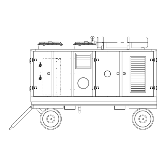
2. STANDARD SPECIFICATION The Zamil MAC240 mobile air-conditioning equipment consisting of a dual system refrigeration section (condensing unit), air handling section, and a power generation unit encased in one complete enclosure. The power generator in the unit is a diesel fed engine which provides power of 460V-3PH-60HZ to the motors in the equipment. - Page 6 UNIT TOP VIEW & ACCESS DOOR LOCATION • Complete back side access is provided with two easy open lockable latched hinged doors to access the power genera- tor and its components. The first one is to access the genset’s control panel and provided with outer sight glass allowing quick visual monitoring to genset operation without the need of opening the access door.
-
Page 7: Diesel Engine Generator
The trolley system is designed with front turnable axle by means of swivel bearing and both front and rear axles are mounted on heavy duty leaf springs allowing the required vibration damping to the upper components. This design allows towing the MAC240 from the front side of the trolley toward the swivel bearing by means of rigid heavy duty beak supported towing bar as well as it can be lifted by forklift safely. - Page 8 B. Alternator This type alternators are brushless, self-regulating and incorporate a rotating inductor with damper cage winding and a fixed stator with skewed slots. The stator windings have a shortened pitch to reduce the harmonic content of the output waveform. The alternators are made in compliance with the 98/37, 73/23, 89/336 CEE directives and their amendments, and the CEI 2-3, EN 60034-1, IEC 34-1, VDE 0530, BS4999-5000, CAN/CSA-C22.2 N°14-95 - N°100-95 regulations.
- Page 9 D. Alarms & Shutdowns:...
-
Page 10: Unit Physical Data
2.3 UNIT PHYSICAL DATA MODEL NUMBER MAC240 NOMINAL CAPACITY (TONS) @ 95 F AMBIENT CAPACITY (TONS) @ 115 F AMBIENT APPLICATION INDUSTRIAL, 100% FRESH AIR POWER SUPPLY (V-PH-HZ) 460-3-60 COMPRESSOR Type SCROLL Part # (Qty.) 800-674-19 (2) Refrigerant R-22 Operating charge per system, oz RLA/LRA, Amps 19.6/125 CONDENSER FAN &... -
Page 11: Unit Specification Summary
2.3.1 UNIT SPECIFICATION SUMMARY 1. GENERAL • Length (overall): 141.7 inches (3600mm) • Width (overall): 86.9 inches (2210 mm) • Height (overall): 104.5 inches (2654mm) • Weight (approximate): 8800 lbs (4000 kg) • Storage Temperature: 40 ° F to 120 °... -
Page 12: Air Conditioning Section
2.4 AIR CONDITIONING SECTION (ACU) The factory assembled Air Conditioning unit has cooling or combination of heating (optional) and cooling as a single package, suitable for mobile applications. The cooling system consists of two stage refrigeration compressors, with each stage having a closed loop circuit in which the refrigerant is circulated by the pressure differential created by the com- pressors. -
Page 13: Electrical Enclosure Assembly
2.5 ELECTRICAL ENCLOSURE ASSEMBLY The unit has two electrical enclosures, one for the generator engine’s control and the other serves as the unit’s main control panel. The main unit control panel enclosure is designed with hinged access door and according to NEMA 4 requirements. The internal power and control wirings are neatly routed and with cable markers for identification as per NEC regulation. -
Page 14: Operating From External Power Source
2.6 OPERATING FROM EXTERNAL POWER SOURCE The equipment may also be operated from an external power source. The power source rating shall be having a nominal voltage rating of 460V-3PH-60HZ and can adequately handle the equipment’s power consumption of 55KVA. When the equipment is operated from an external power source, ensure that the generator’s circuit breaker is switched “OFF”... - Page 15 SCHEMATIC REFRIGERATION DIAGRAM...
-
Page 16: Major Refrigeration Components
3.3 MAJOR REFRIGERATION COMPONENTS The model MAC240 is equipped with two Copeland hermetic scroll compressor. The compressors have a rated cooling capacity of 12 tons each and one compressor is used in each refrigerant circuits. Located in the condensing section and are accessible through front access door. - Page 17 The scroll compressor consists of two involutes or Archimedean spirals. One spiral is positioned inside the other to form a series of crescent-shaped pockets. During compression the upper spiral remains stationary and the lower one, being eccentrically mounted on the drive shaft, describes an orbital rather than a simple rotary motion. How a Scroll Compressor works: Compression in the scroll is created by the interaction of an orbiting spiral and a stationary spiral.
-
Page 18: Condenser Coil
Refrigerant enters the compressor at the suction connection and flows around the motor’s housing and enters at the bottom side through the openings. Oil droplets separate from the refrigerant and fall into the oil sump. All suction refrigerant passes through the electrical motor, ensuring full motor cooling. After that the refrigerant enters the scroll elements. -
Page 19: Hot Gas By Pass Control
3.3.7 Hot Gas By-Pass Control Hot gas bypass control is provided in the both circuit to permit operation of the system down to 80 % of its unloaded capacity. Under low ambient condition, it controls temperature by eliminating the need to cycle the compressor on and off, ensuring narrow temperature swing and lengthen the life span of the compressor. -
Page 20: Refrigeration System Assembly
3.4 REFRIGERATION SYSTEM ASSEMBLY COMPRESSOR EVAPORATOR COIL CONDENSER COIL EXPANSION VALVE VIBRATION ELIMINATOR HGBP LINE VIBRATION ELIMINATOR MUFFLER BALL VALVE... -
Page 21: Control System
4. CONTROL SYSTEM 4.1 GENERAL DESCRIPTION: The ACU section control is managed by a 16-bit microprocessor board fixed in the main control panel with a separate LCD display as user’s interface. The control board completely controls the operation of the refrigeration system; i.e., compressors and condenser fan motors, and the variable frequency drive. -
Page 22: Low Cool
Compressor Run/Off Timing in Different Cooling Modes a) Low Cool Mode – In this mode, cooling is in intermittent operation. Cooling is active for 10 minutes and stops for 3 minutes in every 13 minutes timing interval. Compressors are alternated in a way that at least one compressor in the unit is running for 10 minutes for every 13 minutes interval. -
Page 23: Supply Fan Speed Control
4.3 SUPPLY FAN SPEED CONTROL 4.3.1 General description The supply fan motor is connected to a variable frequency drive device (VFD) to regulate its speed and thereby control- ling the air flow. At start-up, the motor will gradually increase its speed until the desired or set CFM is met. The device may give an output to gradually increase or decrease the speed of the motor depending on the analogue signal (0~10V) coming from the microprocessor board. - Page 24 Main Control Panel Switches & Indicators The description and function of each of the switches and lamps are as follows: Temperature LCD Display – This LCD window will display the temperature of the supplied air. In the process of parameter changing, the LCD will display the data that is being changed – either the parameter number or the parameter value.
-
Page 25: Generator Set Control Panel
16) ACU Alarm Lamp – This lamp will light if there’s a fault in the ACU system. The nature of the fault will be described in the LCD window #2 of the ACU’s control panel. 17) Alarm Reset Button – If there’s a fault, pushing this button will re-set the system. The lighted fault indicating lamps will be turned off. -
Page 26: Sensors
The description and functions of the control buttons on the module panel are as follows: 1) Stop/Reset Button – This button places the module into its stop/reset mode. This will clear any alarm conditions for which the triggering criteria have been removed. The fuel supply will be removed and if the engine is running, it will be brought to a stand still. -
Page 27: Start-Up & Shutting Down Sequence
The description and function of the sensors are as follows: a) Air Velocity Sensor – The function of this sensor is to measure the air velocity (mass flow). The working range air velocity is adjustable up to 20 m/s. Output signal is 0~10V range and transmitted to the microprocessor board which will in turn send to the VFD for supply fan speed control. - Page 28 WARNING: NEVER SMOKE OR ALLOW AN OPEN FLAME WITHIN THE IMMEDIATE VICINITY OF THE UNIT WHILE SERVICING FUEL. NEVER SERVICE UNIT WITH THE ENGINE OPERATING. FAILURE TO COMPLY MAY RESULT IN POTENTIAL HAZARD WARNING: POTENTIAL FOR FUEL FIRE OR FUEL EXPLOSION CAUSING SEVERE EQUIPMENT DAMAGE AND/ OR SEVERE INJURY, EVEN DEATH TO PERSONNEL FROM SKIN BURNS.
-
Page 29: Starting The Generator Engine
5.2 STARTING THE GENERATOR ENGINE Switch “ON” the isolating switch of the DC battery in the generator set section. The “lever” should be pointing towards the operator to be in “ON” position. b) Turn the key provided in the generator module to switch “ON” power to the module. The module’s LCD display will be illuminated and information appearing on it. -
Page 30: Machine Shutdown
5.4 MACHINE SHUTDOWN a) The system is stopped by pressing again the ON/OFF” button on the user interface board. The “ON” LED is switched “OFF” and on the LCD display will show the status “STOPPING”. All the compressors will stop and the supply fan shuts off after a pre-set timing of 30 seconds. -
Page 31: Alarm And Trouble Shooting Guide
6. ALARMS AND TROUBLESHOOTING GUIDE 6.1 DESCRIPTION OF ALARMS (FAULT) This section describes the various alarms that can be shown in the LCD display of the user interface board in the main control panel. The alarms are handled only if the controller is in “ON” status. Once the alarm condition has been reset the error message disappears automatically or, in some particular cases, will remain until the ESC button is pressed. -
Page 32: Trouble Shooting Guide
6.2 TROUBLE SHOOTING GUIDE FAULT DESCRIPTION PROBABLE CAUSE CORRECTIVE MEASURE LCD DISPLAY SYMPTOM No Air Circulation a) Loosed wiring connections on relay - Check and Re-tighten wiring connec- Supply AR4-3B (NC) terminal to terminal A11 tion. Motor Stopped or Not Starting of MB board. -
Page 33: Protection Devices
FAULT DESCRIPTION PROBABLE CAUSE CORRECTIVE MEASURE LCD DISPLAY SYMPTOM Low Refrigerant pressure # Suction Pres- Check hot gas by-pass solenoid if not Compressor Stopped or sure Low getting activated, replace if damaged Not Starting Check for leaks in suction line, re- pair and add refrigerant charge. -
Page 34: Accessories
8. ACCESSORIES 8.1 FUEL FILL STATION ASSEMBLY The Diesel fuel fill station assembly is mounted on the side of the unit. This assembly contains a Protecto-Seal cap, an electrically operated fuel level gauge with “push-to-check” switch and a level gauge to indicate fuel quantity available in the tank. -
Page 35: Maintenance & Servicing
This Preventive Maintenance Schedule is only for quick reference and not replacing the manufacturer manual by any means which shall be followed by the users. Therefore, please read and follow the manufacturer manual before and during operation without any responsibility on Zamil Air Condi- tioners. - Page 36 Operation Daily 125 500 1000 12000 hour hour hour hour hour hour year year E20 E30 E40 E50 E60 E70 Fuel System Inspect for leaks Replace Fuel filter cartridge 10 Clean Fuel pre-cleaner 11 Drain sediment from tank Engine Cooling System (Air Cooled) 12 Inspect air intakes for restrictions 13 Check or clean cooling system (see the manual for more information) 14 Clean Intake air cleaner/dry type air cleaner (If available, maintain...
-
Page 37: Air Conditioning System
Frequency of maintenance, Months Operation Every time used Air Conditioning System 36 Clean Pre- & Final air filters & replace if required. 37 Clean evaporator coil, drain pan & drain line. 38 Clean condenser coil. 39 Lubricate blower motor/condenser motor. 40 Check/clean electrical connections, controls &... -
Page 38: Air Conditioning System
9.3 AIR CONDITIONING SYSTEM The Model MAC240 Air Conditioner Unit provides reliable operation while requiring a minimum of service and mainte- nance. This chapter contains information on servicing and maintaining the unit for optimum performance. Detailed ser- vice and maintenance procedures on the diesel engine generator set may be found in the manufacturer’s publication manual. -
Page 39: Moisture In A Refrigerant System
9.4 MOISTURE IN A REFRIGERANT SYSTEM: The filter drier in the system removes particles and small amounts of moisture which may enter the system during minor servicing or fault conditions. Major moisture intrusion through fault or contamination may require complete system evacu- ation for moisture removal. - Page 40 TABLE-2: BOILING TEMPERATURES OF WATER AT CONVERTED PRESSURE Temperature in Degrees Inches of Vacuum Microns Pounds Per Square Inch Fahrenheit ( (Pressure) ° ° 0.00 759,968 14.696 ° 5.00 535,000 12.279 ° 9.81 525,526 10.162 176° 16.02 355,092 6.866 ° 20.80 233,680 4.519...
-
Page 41: Evacuating The Refrigerant System
9.5 EVACUATING THE REFRIGERANT SYSTEM Anytime the compressor or refrigerant system is exposed for long periods of time to atmospheric air, becomes contami- nated, or requires removal of the refrigerant charge, evacuate the system using the procedures that follow. CAUTION: POTENTIAL FOR SERIOUS DAMAGE TO THE MOTOR WINDINGS IN THE COMPRESSOR. -
Page 42: Refrigerant Leak Repair
(1) TESTING METHODS (a) Electronic Leak Detector: This is the easiest method for leak detection. Electronic leak detectors can be used in areas where an open flame is not permitted. Pass the detecting probe over the area of the suspected leak. If a leak is present, the detector sounds a high frequency alarm or signals by a flashing light, depending on the model used. -
Page 43: Refrigerant Charging & Pressure Limits
9.8 REFRIGERANT CHARGING & PRESSURE LIMITS If the air conditioning unit is to provide the proper amount of cooling, the refrigerant system needs to be adequately charged with R-22 refrigerant. A shortage of refrigerant is evident by a loss of cooling effect, a low suction pressure, and many bubbles present in the sight glass. -
Page 45: Component Layout (Main Control Panel)
11. MAIN CONTROL PANEL COMPONENT LAYOUT... -
Page 46: Component Parts List (Main Control Panel)
12. MAIN CONTROL PANEL COMPONENT PARTS LIST... -
Page 47: Parts List
13. PARTS LIST –MAC240 ZAMIL Part No. Description 04940003 REFRIGERANT – FREON 22 (PER SYSTEM) 60020008 WRG DGM MOBILE AC/MAC240 FZ601 460V-3-60 HZ 80000502 AIR FLOW SWITCH 80000934 FUSDEL DUAL ELEMENT 2 AMP 250V 80000937 FUSDEL DUAL ELEMENT 3.5AMP 250V... - Page 48 SIGHT GLASS 2870 A203 OBP30 FOR 30" PANEL 80020708 VALACE MADEN VU 53-346. ACCESS VALVE 80020725 VALACE 1/4 MPT ACCESS VALVE 80021220 STKADH ZAMIL ALUM. FOIL 80022601 FAN ASSY ZIEHL (700mm) FC071 6DQ 6K5 460/400-3-60/50 80023703 FAN ASSY [710mm]OD, SINGLE SPEED, 230/460/400-3-60HZ 80024910 AL.
- Page 49 PARTS LIST –MAC240 ZAMIL Part No. Description 80030082 TERM MARKER TAG # 2 SYMBOL (10NOS./STRIP) 80030083 TERM MARKER TAG # 3 SYMBOL (10NOS./STRIP) 80030084 TERM MARKER TAG # 4 SYMBOL (10NOS./STRIP) 80030085 TERM MARKER TAG # 5 SYMBOL (10NOS./STRIP) 80030086 TERM MARKER TAG # 6 SYMBOL (10NOS./STRIP)
- Page 50 PARTS LIST –MAC240 ZAMIL Part No. Description 80044421 LABADH CB3 80044422 LABADH CB4 80045026 LABADH 7/16" x 1/2" F1 80045027 LABADH 7/16" x 1/2" F2 80045028 LABADH 7/16" x 1/2" F3 80045029 LABADH 7/16" x 1/2" F4 80045057 LABADH 7/16" x 13/16" CB5 80045140 LABADH ADHESIVE 7/16"x13/16"...
- Page 51 PARTS LIST –MAC240 ZAMIL Part No. Description 80064650 USER INTERFACE CARD-CH [PJE] 80064655 PTC TEMP SENSOR (L=7M) FOR LWT&RWT CH(PJE) 80064656 RELATIVE PR TRANSDUCER (0TO40BAR)(FOR DP)[PJE] 80064658 RELATIVE PR TRANSDUCER (-05TO10BAR)(FOR SP) [PJE] 80064659 CONNECTOR SERIAL INTERFACE RJ45 -CH 80064660...
-
Page 52: Parts List
PARTS LIST –MAC240 ZAMIL Part No. Description 80107915 WASHER M10 DIN 9021 A2 80107918 WASHER M5 x 5.3mm - GAL DIN 125 80107919 WASHER 6.4 VZ DIN 125 80107920 WASHER 8.4 VZ 80107921 WASHER 10.5 DIN 125 VZ 80107930 WASHER M12 VZ DIN9021 80107947 SPRING WASHER M5 x 5.1mm - GAL DIN 127... -
Page 53: Wiring Diagram
14. WIRING DIAGRAM POWER SUPPLY SCHEMATIC DIAGRAM MAC 240 460V-3PH-60HZ 2-FAN MOTOR LAYOUT HVTB POWER SUPPLY (GEN SET PANEL) CONTROL PANEL VFD CONTROL CONNECTIONS LUG/ETB (MB) AO3(-) (MB) AO3(+) FMC1 FMC2 (MB) UVM CONNECTION OLR1 OLR2 (MB) Ø Ø Ø COMP COMP UVM-1... -
Page 54: Wiring Diagram
WIRING DIAGRAM POWER SUPPLY SCHEMATIC DIAGRAM EXHAUST FAN POWER AND CONTROL CONNECTION 460V-3PH-60HZ TO GEN SET CB (SUPPLY SIDE) TO ATB TO ATB FMC3 230V ac TRANS3 (75VA) TK(FM3) FMC3 230V FUEL GAUGE CONNECTION GEN SET FUEL GAUGE CONTROL PANEL SW8 24V AC LAMP A1 (SSPS-1) -
Page 55: Symbols And Legends
15. SYMBOLS AND LEGEND EMERGENCY STOP CONTACTOR COMPRESSOR # PUSH BUTTON SWITCH FMC # TOGGLE SWITCH COMP CONDENSER FAN A/CR_# MOTOR (NORMALLY CLOSE CONTACT) MOTOR HVTB SOLENOID VALVE TERMINAL BLOCK FMC# CONTACTOR COIL CONDENSER FAN # HGS# - HOT GAS BY-PASS (MAIN POWER CONNECTION) CONDENSER FAN MOTOR... - Page 60 COIL SECTION...
- Page 61 FAN & MOTOR ASSEMBLY...
- Page 62 CONDENSER SECTION...
- Page 64 MAIN CONTROL BOX...
- Page 66 GENERATOR DISPLAY PANEL...
Need help?
Do you have a question about the MAC-240 and is the answer not in the manual?
Questions and answers