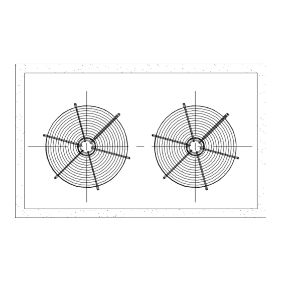
Summary of Contents for Zamil CX SERIES
- Page 1 INSTALLATION, OPERATION & MAINTENANCE MANUAL AIR COOLED CONDENSING UNITS CX SERIES (CX150 - CX360) Part Number: 800-213-58 (Rev.-02)
-
Page 2: Table Of Contents
INDEX Contents Page Model decoding ............................2 General statement ............................ 2 Warranty ..............................2 Safety issues ............................2 Inspection for damage ..........................2 Installation procedures ..........................3 Service clearance ............................. 3 Dimensions ............................4-6 Rigging & mounting ..........................7 Refrigerant piping connection ........................8 Leak testing &... -
Page 3: Model Decoding
GENERAL STATEMENT These units are from the Classic CX series that was designed and built for the optimum performance when matched with the right indoor unit (Refer to indoor unit catalog). However, it is required that you become well acquainted with good practices for the proper installation, operation, and maintenance procedures in order to ensure a safe trouble free operation, year after year. -
Page 4: Installation Procedures
INSTALLATION PROCEDURES GENERAL These units are shipped completely assembled, charged with refrigerant (R-22) and wired. They will require external power & thermostat wiring in the field. Selection of the condensing unit and its corresponding matching indoor unit should be based on a heat calculation made according to applicable standards. Units must also be installed in accordance with regulations of the “National Fire Protection Association”... -
Page 5: Dimensions
DIMENSIONS CX150 - CX220 NOTE: 1. All dimensions are in mm (dimensions in brackets are in inches). - Page 6 DIMENSIONS CX 240 - CX 300 NOTE: 1. All dimensions are in mm (dimensions in brackets are in inches).
- Page 7 DIMENSIONS CX 360 2121 [83.50"] [2.88"] [37.13"] [37.13"] 2197 2032 [86.50"] [80.0"] NOTE: 1. All dimensions are in mm (dimensions in brackets are in inches).
-
Page 8: Rigging & Mounting
RIGGING & MOUNTING These units are suitable for overhead rigging. See below rigging instructions. Attention to Riggers: 1. Hook rigging sling through holes/insert 3" nominal pipe through holes in the base rail, as shown below. 2. Holes in base rail are centered around the unit center of gravity. 3. -
Page 9: Refrigerant Piping Connection
REFRIGERANT PIPING CONNECTIONS Piping connections: Outdoor units should be connected to indoor units using field-supplied piping of refrigerant grade and correct size. The liquid and suction line diameters can be determined from the physical data table. For piping applications beyond 25 feet (7.62 m), please follow the instructions from ZAC refrigerant pipe sizing manual. -
Page 10: Typical Wiring Diagram
TYPICAL SCHEMATIC WIRING DIAGRAM MODELS : CX150 (SINGLE COMPRESSOR UNITS) HVTB POWER SUPPLY LOW AMBIENT OPTION CONNECTION PLS. REFER UNIT NAME PLATE CIRCUIT BREAKER OPTION APPLICABLE FOR 230V - 1PH FAN MOTOR WRG DGM SUITS 230V/3PH/60Hz 460V/3PH/60Hz & HVTB 380V/3PH/60Hz TO CC TO CC T1A/71A... - Page 11 RESULT IN COMPRESSOR DAMAGE. 4. FUSED DISCONNECT SWITCH OR CIRCUIT BREAKER TO BE PROVIDED BY END USER WITH RATING AS RECOMMENDED BY ZAMIL. 5. IF PDS IS FACTORY INSTALLED, PLEASE READ BROKEN LINES AS CONTINUOUS LINES. 6. ALLOW 2-3 MINUTES FOR SSPS SWITCH TO CLOSE, BEFORE STARTING THE UNIT.
- Page 12 TYPICAL SCHEMATIC WIRING DIAGRAM MODELS : CX180 - CX220 (DUAL COMPRESSOR UNITS) HVTB POWER SUPPLY PLS. REFER UNIT NAME PLATE WRG DGM SUITS 230V/3PH/60Hz 460V/3PH/60Hz 380V/3PH/60Hz NOTE: 1.NTB IS APPLICABLE FOR 380V/3PH/60Hz 2.FOR UNIT WITH ABOVE VOLTAGE CONNECT 37A,37B OF 1PH FM &...
- Page 13 RESULT IN COMPRESSOR DAMAGE. COMP2 4. FUSED DISCONNECT SWITCH OR CIRCUIT ATB(8) BREAKER TO BE PROVIDED BY END USER WITH RATING AS RECOMMENDED BY ZAMIL. 5. ATB (3) & (5) IS APPLICABLE FOR PDS OPTION UNITS FR2-2 ONLY. FR2-2 6. ALLOW 2-3 MINUTES FOR SSPS SWITCH TO CLOSE, BEFORE STARTING THE UNIT.
- Page 14 TYPICAL SCHEMATIC WIRING DIAGRAM MODELS : CX240 - CX360 (DUAL COMPRESSOR UNITS) HVTB POWER SUPPLY PLS. REFER UNIT NAME PLATE WRG DGM SUITS 230V/3PH/60Hz FOR FAN MOTOR COMPRESSOR CONN. WITH PART WIND START 460V/3PH/60Hz CONNECTIONS SEE BELOW 380V/3PH/60Hz HVTB NOTE: 1.NTB IS APPLICABLE FOR OLR1 OLR2...
- Page 15 UNIT ON UNIT OFF BREAKER TO BE PROVIDED BY END USER WITH B. COMP ON,OFF&TRIP[&]UNIT TRIP INDICATION OPTION RATING AS RECOMMENDED BY ZAMIL. B. FOR UNITS WITH 1 UNLOADER COMP 1: COMP 2: 5. IF PDS IS FACTORY INSTALLED, PLEASE READ...
-
Page 16: Operating Instruction
Dirty coils can be cleaned using a soft brush or by flushing with cool water or commercially available coil cleaners. DO NOT USE HOT WATER OR STEAM in cleaning the coil. COMPRESSOR MAINTENANCE Maintenance is limited to visual checking for oil leakage and electrical connections. In case of failure contact Zamil sales/ dealer office. -
Page 17: Preventive Maintenance Schedule
PREVENTIVE MAINTENANCE SCHEDULE CAUTION: Disconnect power supply and allow all rotating parts to stop before servicing the unit. FREQUENCY OF MAINTENANCE, MONTHS (FIRST 4 YEARS) I T E M Check all electrical controls, components, wiring terminals, etc..., for sparks, over heat, loose connections & repair or correct it Clean condenser coil Check motors, blower bearings &... -
Page 18: Trouble Shooting Chart
TROUBLE SHOOTING CHART SYMPTOM CAUSES CHECK & CORRECTIVE MEASURE 1. Line disconnect switch open 1. Close start or disconnect switch Compressor will not start, no hum. 2. Fuse removed or blown 2. Replace fuse 3. Overload protector tripped 3. Refer to electrical section 4. - Page 19 TROUBLE SHOOTING CHART SYMPTOM CAUSES CHECK & CORRECTIVE MEASURE Head pressure too high 1. Refrigerant overcharge 1. Correct the refrigerant charge 2. Air in system 2. Recharge the system after a thorough triple evacuation 3. Dirty condenser 3. Clean 4. Malfuction of condenser fan (air-cooled) 4.
-
Page 20: Parts List
PARTS LIST MODEL NUMBER CX150H CX150M CX150F CX180H CX180M CX180F COMPRESSOR (Single),Scroll 800-674-17 800-674-18 800-674-19 N.A. N.A. N.A. . COMPRESSOR (Dual), Scroll 800-674-23 800-674-24 800-674-25 800-674-79 800-674-80 800-674-81 FAN MOTOR 800-545-58 800-545-58 800-545-63 800-545-68 800-545-68 800-545-68 FAN MOTOR CAPACITOR 800-572-20 800-572-20 800-572-20 N.A.


Need help?
Do you have a question about the CX SERIES and is the answer not in the manual?
Questions and answers