Table of Contents
Advertisement
Advertisement
Table of Contents

Subscribe to Our Youtube Channel
Related Manuals for Superlift RDO1 C


Summary of Contents for Superlift RDO1 C
- Page 1 801-001-01 C...
-
Page 2: Important Safety Recommendations
As a result the object/person/door may suffer DAMAGE OR INJURY. Make sure that the door is fully open before driving into or out of the garage. Make sure the door is fully closed before leaving the driveway. - 2 - RDO1 C... -
Page 3: Operation
Manual Mode by pulling down once on the release cord/ handle and releasing. This will allow you to manually open or close the door. When power is restored the Opener can be re-engaged by pulling down once more on the release cord/lever. - 3 - RDO1 C... -
Page 4: Operating Controls
OPERATING CONTROLS - 4 - RDO1 C... - Page 5 16. ENGAGE/DISENGAGE LEVER. Alternatively engages/disengages opener from the door. 17. EXTERNAL PUSH BUTTON alternatively opens, closes or stops the door when activated. 18. VOLTAGE SELECTION TERMINALS switches the input voltage between 115 and 240 volts - 5 - RDO1 C...
-
Page 6: Important Note
The ideal operational effort, required to open or close the door, should not exceed a force of 10kg. Superlift does not recommend the installation of an Automatic Opener to a badly worn or damaged door. -
Page 7: Control Box
Control Box as depicted in Fig 7. To switch the power supply leads, remove the Control Box cover. Locate and un-plug the plastic connectors marked “240V” (Black and Brown coloured wires) and plug-in to the connectors marked “115V” (Black and Blue) coloured wires). The switch to 115 volts is now complete. - 7 - RDO1 C... -
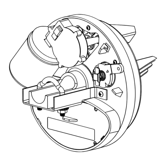
Page 8: Installation Instructions
Remove the Drive Unit from the packaging. Rotate the forked drive gear by pushing the fork. If the drive gear does not rotate, turn the Lock/Release leaver. Fig 2 (For more instructions on how to “Lock” and “Release” the Drive Gear refer to Section 11) Fig10 Fig 11 - 8 - RDO1 C... - Page 9 2.1 The door curtain must be secured to the drum wheel with suitable fasteners. 2.2 With the door in the fully closed position, mark the curtain at points (A) and (B) Fig 13 Fig 13 - 9 - RDO1 C...
-
Page 10: Setting The Limit Switches
Fig 1 4.10 Plug the Control Cable into the bottom of the Control Box. 4.11 Fix the Control Cable to the wall using the Cable Clips provided. 4.12 Plug the Power Cable into a power socket. - 10 - RDO1 C... - Page 11 Control Box. As the door commences to OPEN, slowly begin to turn the UPPER “SOF” screw in an ant clockwise direction until the door stops. Now turn the adjustment back 10 degrees in a CLOCKWISE direction. Note: The door must stop before it reaches the fully open position. - 11 - RDO1 C...
- Page 12 11.1 Pull on the Red Release cord, or turn the release handle manually, to alternatively lock/release the drive mechanism 12. FITTING OF PHOTO ELECTRIC (PE) SAFETY BEAMS (OPTIONAL) 12.1 Mount the PE beam brackets in accordance with. - 12 - RDO1 C...
-
Page 13: Auto Close Function
433 MHz No. of CODE COMBINATIONS: Over 4.9 Billion TRANSMITTER BATTERY VOLTAGE: 12 Volt MOTOR TYPE: 24 Volt DC Permanent Magnet GLOBE: 15W 24 V DC Edison screw Type SAFETY REVERSING SYSTEM: Pot Adjustable Current Sensing - 13 - RDO1 C... -
Page 14: Troubleshooting Guide
Repair P.E. or broken wire P.E. Beam faulty or wiring broken Remove obstruction from the Auto close not working P.E. Beam obstructed path of beam. Auto close time not set Refer to installation inst. - Items 13 & 14. - 14 - RDO1 C... - Page 15 CONTROL BOX MOUNTING TEMPLATE - 15 - RDO1 C...
Need help?
Do you have a question about the RDO1 C and is the answer not in the manual?
Questions and answers