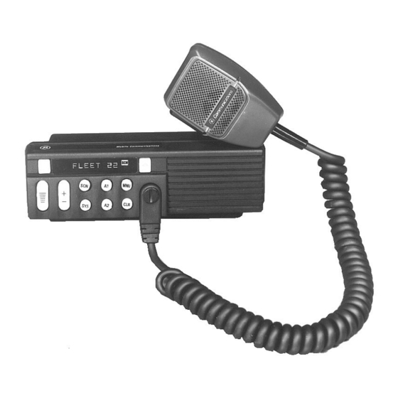
Ericsson MDX SERIES Installation Manual
Conventional mobile radio
Hide thumbs
Also See for MDX SERIES:
- Installation manual (28 pages) ,
- Operator's manual (16 pages) ,
- Service manual (15 pages)
Table of Contents
Advertisement
Quick Links
Download this manual
See also:
Service Manual
Advertisement
Table of Contents

Related Manuals for Ericsson MDX SERIES


Summary of Contents for Ericsson MDX SERIES
- Page 1 LBI-39013 Mobile Communications ™ SERIES (Conventional Mobile Radio) MOBILE RADIO Installation Manual...
-
Page 2: Table Of Contents
EXTERNAL SPEAKER KIT - OPTION PMZM1K ..BRAMCO DECODER INSTALLATION NOTES ..OPTION INTERCONNECTION DIAGRAMS ..Copyright© October 1992, Ericsson GE Mobile Communications Inc. -
Page 3: Introduction
IBM compatible personal computer and the following items: Serial Programming Interface Module Kit and TQ3370 Programming Cable TQ3372 MDX Series Programming Software TQ3346 (Conventional Mobile Radio) UNPACKING AND CHECKING EQUIPMENT When ready for installation, carefully unpack the radio and identify each item in the shipping container as listed below. - Page 4 Table 1 - MDX Mobile Radio Series Optional Accessories Option Description Part Number PMAN1R Roof mount antenna with TNC connector PMCC02 Universal tone cable (used with V8001, V8022, V8024, each). PMCC9M External speaker cable, 18 inches 19A149590P8 PMCD1W External speaker cable, 16 feet, requires 19A149590P10 option PMZM1K and PMCD7Z PMCD7C...
-
Page 5: Planning The Installation
PLANNING THE INSTALLATION Before starting, plan the radio installation carefully so that it will be: • safe for the operator and passengers. • convenient for the operator to use. • neat. • protected from water damage. • easy to service. •... -
Page 6: Equipment Required
EQUIPMENT REQUIRED The equipment required for installing the MDX Mobile Radio is listed below: • Electric drill for drilling mounting holes. • Drills and circle cutters as follows: • No. 31 (1/8-inch) drill for No. 8 self-tapping screws. • No. 27 (9/64-inch) drill for No. 10 self-tapping screws. •... -
Page 7: Installation In Vehicles Powered By Liquefied (Lp) Gas
INSTALLATION IN VEHICLES POWERED BY LIQUEFIED (LP) GAS Radio installation in vehicles powered by liquefied petroleum gas with the LP-gas container in the trunk or other sealed-off space within the interior of the vehicle must conform to the National Fire Protection Association Standard NFPA 58 which requires that: •... -
Page 8: Installation
INSTALLATION RUNNING CABLES To assure the feasibility of the planned cable routings, it is suggested that the cables be run before mounting the radio. Be sure to leave some slack in each cable going to the radio so that the radio may be pulled out for servicing with the power applied and antenna attached. - Page 9 4. Push the prepared fuse connectors into each section of the fuse holders. Place the fuse into a fuse holder section until it seats within the connector. Connect the fuse holder sections to insure a tight fit and connection. Figure 3 - Power Cable...
- Page 10 Connect the orange fused lead to the positive (+) battery terminal, and black to the negative (-) battery terminal. Always locate the fuse as close to the battery as possible. Connect the red fused lead to the ignition "on" sense point (preferably an "Accessory"...
-
Page 11: Mounting The Radio
Coil any surplus cables and secure them out of the way with the retaining strap provided. Be sure to leave some slack in the cables going to the radio so that it may be pulled out for servicing with power applied. MOUNTING THE RADIO Figure 4 - Mounting Dimensions Use the supplied mounting bracket as a template to locate the positions for... -
Page 12: Microphone Hanger
Figure 5 - Mounting Bracket Installation MICROPHONE HANGER Mount the microphone hanger in a location convenient to the operator where it will not interfere with the safe operation of the vehicle or be a hazard to the vehicle passengers. The microphone hanger is designed to be mounted with the open end of the mounting button slot pointed upward. - Page 13 Figure 6 - Microphone Hanger NOTE If mounting on a surface covered with carpet, punch holes with a small punch then make a small slit in the carpet, insert a short piece of metal tubing and drill through the tubing. Use the following procedure to mount the microphone hanger: 1.
-
Page 14: Microphone
MICROPHONE The microphone connects to the MDX Mobile Radio using a plug found at the end of its attached cable. Match the pins on this plug to the pin socket on the radio and press in the plug being sure not to damage the pins. Once the plug is seated, tighten down the plug using the thumbscrew on the mic connector. -
Page 15: Option Cable Kit - Option Pmcd7Z
A permanent mount type of antenna should be located in the center of the roof or center of rear deck. Glass mounted antennas should be kept as high as possible in the top center of the rear window. Some states have laws restricting vision obstructing items from the windows. - Page 16 Figure 8 - Option Cable Pin Locations...
- Page 17 Universal Tone Cable Option PMCC02 (19C851585P19) The Universal Tone Cable requires the Option Cable (Option PMCD7C). P1 of the Universal Tone Cable plugs into P2 of the Option Cable. The Universal Tone Cable Option provides all option connections on P2 and a 9-pin Winchester connector for connecting to external tone encoders or decoders.
-
Page 18: Power Cable - Option Pmcd9A (19B801358P17)
Figure 11 - Bottom View (Cover Removed) POWER CABLE (18 FEET) - OPTION PMCD9A (19B801358P17) Refer to the power and ignition cable installation section starting on page 8 to install this optional power cord. MICROPHONE, MIL SPEC - OPTION PMMC3W (344A4528P55) Refer to the microphone installation section on page 14 to install this optional microphone. -
Page 19: Alarm (Horn) Relay Kit - Option Pmsu1C (19A705499P1)
Table 2 - Option Cable Connections Pins Function P2-1 P2-2 SPEAKER LO P2-3 SPEAKER HI P2-4 MIC HI P2-5 SW A+ P2-6 SERIAL REQUEST (GE-STAR) P2-7 P2-8 CG DISABLE P2-9 SW SPEAKER HI P2-10 AUDIO MUTE P2-11 VOLUME-SQUELCH HI P2-12 MIC LO P2-13 RELAY... - Page 20 3. Crimp an insulated 1/4 inch spade tab receptacle to one end of the #18 red wire. Connect the receptacle to relay lug #86. Cut the red lead so the fuse assembly is close to the voltage source. Install the fuse holder. Attach the other end of the fuse lead to the voltage source with appropriate hardware.
-
Page 21: External Speaker Kit - Option Pmzm1K
EXTERNAL SPEAKER KIT - OPTION PMZM1K The external speaker kit includes a speaker (option PMLS1F) and an external speaker cable (option PMCC9M). External speaker cable (option PMCD1W) is available for use with this kit to place the external speaker up to 16 feet further away from the radio. -
Page 22: Bramco Decoder Installation Notes
BRAMCO DECODER INSTALLATION NOTES For proper operation of Bramco decoders with the MDX radio, the following modifications must be made. Bramco Type 99 Decoder option V8022 (19A149258P11) On the decode board: 1. Cut one end of R120 (20 ohm, 2W resistor) 2. -
Page 23: Option Interconnection Diagrams
OPTION INTERCONNECTION DIAGRAM (188D5198, Sh. 1, Rev. 0) - Page 24 OPTION INTERCONNECTION DIAGRAM (188D5198, Sh. 1, Rev. 0)
- Page 25 OPTION INTERCONNECTION DIAGRAM (188D5198 Sh. 3, Rev. 0)
- Page 26 OPTION INTERCONNECTION DIAGRAM (188D5198, Sh. 3, Rev. 0)
- Page 27 OPTION INTERCONNECTION DIAGRAM (188D5198, Sh. 6, Rev. 0)
- Page 28 Printed in U.S.A.
Need help?
Do you have a question about the MDX SERIES and is the answer not in the manual?
Questions and answers