
Related Manuals for Ericsson LBI-39012A


Summary of Contents for Ericsson LBI-39012A
- Page 1 LBI-39012A Mobile Communications CONVENTIONAL MOBILE RADIO Operator’s Manual...
-
Page 2: Table Of Contents
SCAN SETUP ....STARTING OR STOPPING SCAN ..Copyright© December 1993, Ericsson GE Mobile Communications Inc. TABLE OF CONTENTS... - Page 3 TABLE OF CONTENTS (CONTINUED) ADDING/DELETING TO/FROM SCAN ..RECEIVER SCAN RATE ... . USING THE RADIO WITH SCAN ..OPTIONS ..... . . AVAILABLE OPTIONS .
-
Page 4: Safety Information
SAFETY INFORMATION The operator of any mobile radio should be aware of certain hazards common to the operation of vehicular radio transmissions. A list of possible hazards are: Explosive Atmospheres Just as it is dangerous to fuel a vehicle with the motor running, be sure to turn the radio off while fueling the vehicle. -
Page 5: Safe Driving Recommendations For Users Of Mobile Radios
Two-way FM radio systems must be operated in accordance with the rules and regulations of the Federal Communications Commission (FCC). Operators of two-way radio equipment must be thoroughly familiar with the rules that apply to the intended type of radio operation. Following these rules will help to eliminate confusion, assure the most efficient use of existing radio channels, and result in a smoothly functioning radio network. -
Page 6: Introduction
It is a violation of FCC rules to interrupt any distress or emergency message. As the radio operates in much the same way as a telephone "party line", always listen to make sure that the line is clear - that no one else in on the air - before sending messages. -
Page 7: Controls, Indicators, And Displays
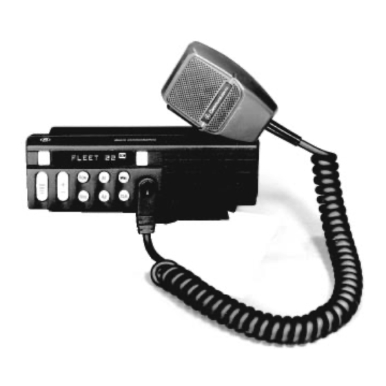
The following feature encrypted options are standard with the MDX conventional mobile radio: PMPL3M PMPL3K PMPL3F PMPL3G PMPL3H PMPL3J The following feature encrypted options can also be ordered: PMPL3C PMPL3D PMPL3E CONTROLS, INDICATORS, AND DISPLAYS The MDX Conventional mobile radio contains ten buttons, an eight character DOT MATRIX display and seven indicators (see Figure 1). - Page 8 8-Character Alphanumeric Dot Matrix LED allows you to identify channel selections by descriptive names. Names, menu options, and status information are displayed here. Scan Button enables scan operation for the selected system. Volume Up/Down Ramp sets the volume of the received audio. Channel/SEL Two Flex Keys Ramp scrolls through...
-
Page 9: Controls And Indicators
CONTROLS AND INDICATORS CONTROLS (CONT’D) MENU SQUELCH Momentary switch. The MENU button is used to access options on the MDX mobile. Menu opera- tion is coupled with the CHANNEL/SEL buttons and the CLR button. To increment from one menu selection to the next, simply press and release the MENU button. -
Page 10: Display Indicators
CONTROLS (CONT’D) CHANNEL/SEL HOME/ EMERGENCY FLEX KEYS A1, A2 DISPLAY INDICATORS The radio’s display is shown in Figure 2. The character line is used to display system or area and group or channel names and also operational messages to the user. The line contains eight Dot Matrix LED characters. The 7 status indicators are used to show the various operating conditions of the radio. -
Page 11: Display Alpha Indicators
Figure 2 - Sample MDX Display DISPLAY ALPHA INDICATORS The radio is capable of displaying status indicators in the alpha display. Some of these messages will use the entire display while others use only two or three characters. When the short message is displayed it may be on the right or left of the display (PC programmable). -
Page 12: Operating The Radio
The MDX Conventional mobile radio generates a set of unique alert tones to indicate operating status. The following section identifies and describes the alert tones used in the MDX radio. SELF CHECK TEST ALERT CALL DISABLED ALERT CARRIER CONTROL TIMER T99 CALL RECEIVED OPERATING THE RADIO TURNING THE RADIO ON... -
Page 13: Select
SELECT To select a different channel when you have selected a conventional system: Press the CHANNEL/SEL + or - ramp button until the desired channel name appears in the alphanumeric display. A tone sounds each time the channel name changes unless the BSY indicator is on. CONVENTIONAL MODE OPERATION Select the conventional channel using +/- ramp button. -
Page 14: Talk-Around
Observe the BSY indicator and then press CLR the switch to assure that the channel is not in use. Remove microphone from the hanger, press the PTT switch and identify yourself. The PTT switch is pressed. Release the PTT switch and wait for an answer to your call. Then complete your message. -
Page 15: Receiver Scan Rate
Press the CHANNEL/SEL (+) button until the desired priority level is displayed by the scan priority indicators on the right side of the display; the choices are S, P2; P1 or all off (all off removes the channel from the SCAN list). Press the CLR button when completed to return to normal operation. -
Page 16: Using The Radio With Scan
Scan operation will be determined by the following conditions: PRIORITY 1, PRIORITY 2 and NON-PRIORITY PROGRAMMED The Priority 1, Priority 2 and up to 14 remaining channels will be scanned. Once a carrier is detected (and if programmed, the correct Channel Guard is decoded), the display will indicate that channel. - Page 17 SCN indicator When the SCAN button is pushed, the radio will light the SCN indicator and begin scanning. The SCN indicator will flash when the microphone is placed off-hook to show the radio is no longer scanning (only if the radio is PC programmed not to scan off-hook).
- Page 18 Monitor (CLR) Switch Operation In Scan The CLR switch does not operate while scanning inactive channels. When a channel becomes active, the CLR switch operates only during the scan hang time after the channel activity disappears. Channel Changes In Scan Pushing the channel switches (UP or DOWN) while scan is turned on will change the SELECTED channel assignment.
-
Page 21: Options
Type 99 Option If the Type 99 Option is present, individual selective calling is possible. Press the programmed Flex key or use the menu and CHANNEL/SEL keys to enable the decoder option (Scan must be off). The LED display will show the option status: "T99 ON"... -
Page 22: Available Options
The following equipment options are available for the MDX radio. Refer to your local radio supplier for ordering information. MDX Conventional Optional Accessories Option Description PMAN1R VHF/UHF roof mount antenna with TNC connector PMCC9M External speaker cable, 18 inches PMCD1W External speaker cable, 16 feet, requires option PMZM1K PMCD7W... - Page 23 Ericsson GE Mobile Communications Inc. (hereinafter "Seller") warrants to the original purchaser for use (hereinafter "Buyer") that Equipment manufactured by Seller shall be free from defects in material, workmanship and title, and shall conform to its published specifications. With respect to any Equipment not manufactured by Seller (except for integral parts of Seller’s Equipment to which the warranties set...
-
Page 24: Telephone Number
FREQUENTLY CALLED NUMBERS MEMORY LOCATION NAME TELEPHONE NUMBER... - Page 25 NOTES...
- Page 26 NOTES...
- Page 27 NOTES...
-
Page 28: Emergency Numbers
EMERGENCY NUMBERS Police State Police Fire Poison Control Ambulance Life Saving and Rescue Squad The following conditions tend to reduce the effective range of two-way radios and should be avoided whenever possible. Operating the radio in low areas of terrain or while under power lines or bridges.
Need help?
Do you have a question about the LBI-39012A and is the answer not in the manual?
Questions and answers