Table of Contents
Advertisement
10/3/23, 11:57 AM
Radio Description
Street Radio 4408
Contents
Introduction
Warranty Seal
Product Overview
Main Features
Optional Equipment
Technical Data
Radio Capabilities
Output Power
Physical Characteristics
Antenna
Installation Recommendations
Space Requirements
Acoustic Noise
Environmental Characteristics
Power Characteristics
System Characteristics
Hardware Architecture
Support 6525
Radio 4408
Antenna
Connection Interfaces
about:blank
Description
344/1551-LZA 701 6001/1 Uen C
Radio Description
Ge27100A
1/20
Advertisement
Table of Contents

Related Manuals for Ericsson 4408


Summary of Contents for Ericsson 4408
- Page 1 10/3/23, 11:57 AM Radio Description Description 344/1551-LZA 701 6001/1 Uen C Radio Description Street Radio 4408 Ge27100A Contents Introduction Warranty Seal Product Overview Main Features Optional Equipment Technical Data Radio Capabilities Output Power Physical Characteristics Antenna Installation Recommendations Space Requirements...
- Page 2 10/3/23, 11:57 AM Radio Description Radio 4408 Standards and Regulations Regulatory Approval Other Standards and Regulations about:blank 2/20...
-
Page 3: Warranty Seal
10/3/23, 11:57 AM Radio Description Introduction Warranty Seal The product is equipped with a warranty seal sticker. Note: Seals that have been implemented by Ericsson must not be broken or removed, as it otherwise voids warranty. about:blank 3/20... -
Page 4: Product Overview
10/3/23, 11:57 AM Radio Description Product Overview The radio expands coverage and performance in denser urban areas, where the use of small handheld devices demand high capacity on the operator networks. It can be mounted on top of luminaires in cities and in demanding radio environments. - Page 5 10/3/23, 11:57 AM Radio Description There is no optional equipment for use with Street Radio 4408. about:blank 5/20...
-
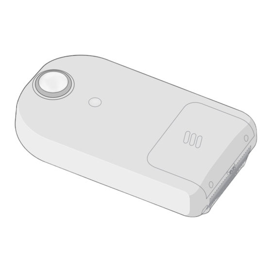
Page 6: Technical Data
For detailed information on licenses and HWACs, see the following: – LTE, NR: Hardware-Related Capabilities in the Radio Node libraries For information on maximum output power per carrier type, see Radio Node Configurations. Physical Characteristics Ge24254A Figure 2 Radio 4408 Dimensions about:blank 6/20... -
Page 7: Installation Recommendations
10/3/23, 11:57 AM Radio Description Ge27101A Figure 3 Support 6525 Dimensions Table 1 Street Radio 4408 Dimensions Product Height, H (mm) Width, W (mm) Depth, D (mm) Radio 4408 B77G Support 6525 With clamp Table 2 Street Radio 4408 Weight... -
Page 8: Space Requirements
3.5.1 Installation Locations to Avoid Although Ericsson declares this product designed for outdoor environments, avoid installing the unit in a potential microclimate location. Typical examples of microclimate locations are sites where the product is not only exposed to the surrounding temperature, but additional temperature as heat from dark-colored planes, for example, reflections from the street asphalt or walls. -
Page 9: Environmental Characteristics
10/3/23, 11:57 AM Radio Description Table 5 Maximum Sound Pressure Level (dBA) for Street Radio 4408 with Integrated Fan Temperature (°C) Street Radio 4408 Sound Pressure Level (dBA) at 1-meter Distance <+20 41.0 44.0 47.0 52.0 The sound pressure level is measured at hemispherical distribution. -
Page 10: Power Characteristics
This section describes the power supply requirements, power consumption, and circuit breaker recommendations for the radio. 3.9.1 AC Power Characteristics The power supply voltage for Radio 4408 is +36 V DC, provided by the Support unit. Table 8 Street Radio 4408 AC Power Supply Requirements Conditions Values and Ranges Nominal voltage 110–480 V AC... -
Page 11: System Characteristics
For general information about RF EMF exposure, see Radio Frequency Electromagnetic Fields. The following tables list the compliance boundaries (exclusion zones), outside of which the RF EMF exposure from Street Radio 4408 is below the limits specified by the FCC and the limits applicable in: – USA (47 CFR 1.1310) Table 10 ... -
Page 12: Hardware Architecture
Radio Description Hardware Architecture For a description of the supported radio configurations, see Radio Node Configurations. Note: The Radio 4408 and Support 6525 units are separately replaceable when faulty. Ge27102A Figure 4 Radio 4408 Table 11 Key to Radio Components... -
Page 13: Mounting Bracket
The PSU is integrated in Support 6525 and provides DC power to Radio 4408 and the fan unit. Radio 4408 Radio 4408 handles the radio communication in the unit and consists of a thermal radiator, TRX, and filter unit. The antenna supervision can detect the following disconnected antennas: –... -
Page 14: Filter Unit
10/3/23, 11:57 AM Radio Description The Transmitter and Receiver (TRX) provides the following: – Analog/Digital (A/D), Digital/Analog (D/A) conversion – Channel filtering – Delay and gain adjustment – RF modulation and demodulation – Optical cable interface termination – Control and surveillance 4.2.3 Filter Unit The Filter Unit consists of band-pass filters. -
Page 15: Connection Interfaces
10/3/23, 11:57 AM Radio Description Connection Interfaces This section contains information about the radio connection interfaces. Radio 4408 Ge27102A Figure 6 Radio 4408 Connection Interfaces Table 13 Connection Interfaces Position Description Marking Connector Types Cable Illustration Antenna A Antenna B... -
Page 16: Dc Power Interface
Installation products. For more information about SFP modules, see Spare Parts Catalog and Site Installation Products Overview. 5.1.3 DC Power Interface The radio DC power connector provides Radio 4408 with +36 V DC and internal communication from the PSU. about:blank 16/20... -
Page 17: Standards And Regulations
Declaration of Conformity " Hereby, Ericsson AB, declares that this product is in compliance with the essential requirements and other relevant provisions of Radio Equipment Directive 2014/53/EU and RoHS Directive 2011/65/EU and Radio Equipment Regulations 2017 and RoHS Regulations 2012. The full text of the declaration of conformity is available at the following internet address: https://portfolio.ericsson.net/c/FGB1010529."... - Page 18 10/3/23, 11:57 AM Radio Description North America – FCC CFR 47 Part 1.1310 – FCC CFR 47 Part 2.1091 – Health Canada Safety Code 6 – IC RSS-102 – UL 62368-1 – CSA-C22.2 No. 62368-1 6.1.2.1 Outdoor-Specific Requirements The Radio System complies with the following outdoor-specific requirements: International –...
- Page 19 10/3/23, 11:57 AM Radio Description 6.1.4 Radio Standards Compliance The Radio System complies with the following radio standards: International – 3GPP TS37.141 – 3GPP TS38.141-1 EU and UK – ETSI EN 301 908-1 – ETSI EN 301 908-18 North America –...
-
Page 20: Other Standards And Regulations
Legal © Ericsson AB 2023 Copyright © Ericsson AB 2023. All rights reserved. No part of this document may be reproduced in any form without the written permission of the copyright owner. Disclaimer The contents of this document are subject to revision without notice due to continued progress in methodology, design and manufacturing.
Need help?
Do you have a question about the 4408 and is the answer not in the manual?
Questions and answers