Table of Contents
Advertisement
Quick Links
Download this manual
See also:
User Manual
HiFi
Zusätzlich erforderliche Unterlagen für den Komplettservice
Additionally required Service Documents for the Complete Service
Service
Manual
Sicherheit
Safety
Materialnr./Part No.
72010 800 0000
Materialnummer/Part Number 72010 760 6000
Änderungen vorbehalten/Subject to alteration • Printed in Germany
E-BS 36 0500 • 8002/8012, 8005/8015, 8006/8016
http://www.grundig.com
Service Manual
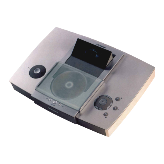
RCD 2000
G.LK 0150
Grundig Service
Technik:
TV
TV
SAT
VCR/LiveCam
HiFi/Audio
Car Audio
Telekommunikation
Fax:
Planatron
(8.00-22.00 Uhr)
Ersatzteil-Verkauf:
Telefon:
Fax:
Hotline Deutschland...
...Mo.-Fr. 8.00-18.00 Uhr
0180/52318-41
0180/52318-49
0180/52318-48
0180/52318-42
0180/52318-43
0180/52318-44
0180/52318-45
0180/52318-51
0180/52318-99
...Mo.-Fr. 8.00-19.00 Uhr
0180/52318-40
0180/52318-50
Advertisement
Table of Contents

Subscribe to Our Youtube Channel
Related Manuals for Grundig RCD 2000


Summary of Contents for Grundig RCD 2000
-
Page 1: Grundig Service
Service Manual HiFi RCD 2000 G.LK 0150 Grundig Service Hotline Deutschland..Mo.-Fr. 8.00-18.00 Uhr Technik: 0180/52318-41 0180/52318-49 Zusätzlich erforderliche Unterlagen für den Komplettservice 0180/52318-48 Additionally required Service Documents for the Complete Service VCR/LiveCam 0180/52318-42 HiFi/Audio 0180/52318-43 Service Car Audio 0180/52318-44... -
Page 2: Table Of Contents
NF-Voltmeter Digital voltmeter AF voltmeter Klirrfaktor-Messgerät Distortion meter Beachten Sie bitte das GRUNDIG Messtechnik-Programm, das Sie Please note the Grundig Catalog "Test and Measuring Equipment" unter folgender Adresse erhalten: obtainable from: GRUNDIG Instruments Test- und Messsysteme GmbH Würzburger Str. 150 D 90766 Fürth/Bay... -
Page 3: Servicehinweis
RCD 2000 Allgemeiner Teil / General Section Servicehinweis Service Hint Die Daten- und Analog-Funkmodule dürfen nur durch autorisierte The Data and Analog RF Modules are allowed to be repaired only Fachbetriebe repariert werden und müssen daher im Defektfall by authorized dealers and are to be exchanged completely in case komplett getauscht werden. -
Page 4: Ausbauhinweise
Allgemeiner Teil / General Section RCD 2000 Ausbauhinweise Disassembly Instructions 1. Boden entfernen 1. Removing the bottom - Die 6 Schrauben (Fig. 1) herausschrauben und den Boden - Undo 6 screws (Fig. 1) and remove the bottom. abnehmen. Fig. 2 Fig. -
Page 5: Cd-Control-Platte
RCD 2000 Allgemeiner Teil / General Section 4. Tuner-Platte ausbauen 4. Removing the Tuner Board - Boden entfernen (Pkt. 1). - Remove bottom (para 1). - 2 Schrauben herausschrauben und Tuner-Platte herausnehmen - Undo 2 screws and remove the Tuner Board (Fig. 3). - Page 6 Allgemeiner Teil / General Section RCD 2000 14. Rechte Tasten ausbauen 14. Removing the right buttons - Tastenplatte rechts ausbauen (Pkt. 12). - Remove the Switch Board right (para 12). - 4 Schrauben herausschrauben und Tasten herausnehmen - Undo 4 screws and remove the buttons (Fig.
- Page 7 RCD 2000 Allgemeiner Teil / General Section Bedienhinweise Dieses Kapitel enthält Auszüge aus der Bedienungsanleitung. Weitergehende Informationen entnehmen Sie bitte der gerätespezifischen Bedienungsanleitung, deren Materialnummer Sie in der entsprechenden Ersatzteilliste finden. AUF EINEN BLICK ______________________________________________________________________ Die Benutzerführung der Fernbedienung Die Fernbedienung Ihrer HiFi-Anlage ist mit einer Benutzerführung ausgestattet.
- Page 8 Allgemeiner Teil / General Section RCD 2000 ANSCHLIESSEN UND VORBEREITEN _____________________________________ Lautsprecher anschließen und installieren Die Audiosignale von der HiFi-Anlage zu den Lautsprechern werden per Funk übertragen. Lautsprecherkabel sind nicht notwendig. Sie können bis zu 6 Lautsprecherpaare an der HiFi-Anlage betreiben.
- Page 9 RCD 2000 Allgemeiner Teil / General Section ANSCHLIESSEN UND VORBEREITEN _____________________________________ Einstellung mit »OK« bestätigen. INSTALL – Anzeige der Fernbedienung: » «, die CONFIRM RIGHT LS WITH OK CONFIRM RIGHT LS Anzeige in der Taste »POWER « des linken Lautsprechers leuchtet orange,...
- Page 10 Allgemeiner Teil / General Section RCD 2000 SONDEREINSTELLUNGEN ________________________________________________________ Lautsprecher im Raum 1 auf „Kabel-Betrieb” schalten Möchten Sie die Lautsprecher im Raum 1 nicht über Funk betreiben sondern mit- tels NF-Kabel an die HiFi-Anlage anschließen, bieten wir Ihnen diese Möglich- keit.
- Page 11 RCD 2000 Allgemeiner Teil / General Section MEHRRAUM-BETRIEB ________________________________________________________________ Einstellung mit »OK« bestätigen. INSTALL – Anzeige der Fernbedienung: » «, SELECT LEFT LS AND PRESS OK SELECT LEFT LS die Anzeige in der Taste »POWER « des linken Lautsprechers blinkt oran-...
- Page 12 Allgemeiner Teil / General Section RCD 2000 MEHRRAUM-BETRIEB ________________________________________________________________ Neuen Lautsprecher auf „altem” Platz anmelden Wenn Sie Lautsprecherpaare, die an der HiFi-Anlage angemeldet sind, aus- tauschen wollen, muß das neue Lautsprecherpaar wieder angemeldet wer- den. »CONTROL« an der Fernbedienung drücken.
-
Page 13: Operating Hints
RCD 2000 Allgemeiner Teil / General Section INFORMATIONEN _____________________________________________________________________ Komponenten in den Auslieferzustand zurücksetzen HiFi-Anlage zurücksetzen HiFi-Anlage mit »O I« einschalten. HORIZONTAL HORIZONTAL »SOURCE« an der HiFi-Anlage so lange drücken, bis » « in der Anzeige erscheint. HiFi-Anlage mit »O I«... -
Page 14: General Section
Allgemeiner Teil / General Section RCD 2000 OVERVIEW __________________________________________________________________________________ The main remote control menus SOURCE The » « menu: SOURCE TUNER » « = Tuner mode TUNER » « = CD mode » « = External tape deck operation TAPE TAPE »... - Page 15 RCD 2000 Allgemeiner Teil / General Section CONNECTION AND PREPARATION _______________________________________ HORIZONTAL Confirm the » « setting by pressing the » « button on the INSTALL HiFi. INSTALL – The HiFi display reads: » «. Insert the three batteries supplied into the remote control battery compart- INSTALL ment, making sure the polarity is correct.
- Page 16 Allgemeiner Teil / General Section RCD 2000 SPECIAL SETTINGS ____________________________________________________________________ Changing the communication channel of the HiFi and the loudspeakers If interference occurs during sound transmission, which can happen if another device is using the same frequency, you can change the communication chan- nel.
-
Page 17: Installing Additional Pairs Of Loudspeakers
RCD 2000 Allgemeiner Teil / General Section MULTIPLE ROOM OPERATION _____________________ Special features of multiple room mode You can operate up to five additional pairs of loudspeakers – distributed in dif- ferent rooms – with the HiFi system. If you do not want to carry the remote control from room to room in order to set... - Page 18 Allgemeiner Teil / General Section RCD 2000 MULTIPLE ROOM OPERATION ________________________________________________ Switching on a pair of loudspeakers Press the »CONTROL« button on the remote control. From the » « menu, select the » « item by pres- CONTROL SELECT ROOM sing »A«...
-
Page 19: Resetting Components To The Original State
RCD 2000 Allgemeiner Teil / General Section MULTIPLE ROOM OPERATION ________________________________________________ Press »OK« to confirm the setting. – The remote control display reads: » SELECT LEFT LS AND PRESS «, the orange indicator in the »POWER « button on the left loud- speaker flashes and the orange indicator in the »POWER... -
Page 20: Adjustment Procedures
Abgleichvorschriften / Adjustment Procedures RCD 2000 Abgleichvorschriften Tuner Messgeräte: Mess-/Wobbelsender, Oszilloskop, Digital-Voltmeter, NF-Voltmeter, Klirrfaktor-Messgerät Hinweis: Das Frontend ist ein komplett abgeglichener Baustein. Nur das ZF-Filter muß dem ZF-Verstärker angeglichen werden (1). Die Abstimmspannungen des Frontends haben folgende Größen: 87,5MHz = typ. 1,6V min 1,3V; 108MHz = typ. 8,0V max 9V... - Page 21 RCD 2000 Abgleichvorschriften / Adjustment Procedures Abgleichlageplan / Alignment Layout ST102 ST101 Frontend FE100 F141 F102 ST171 F171 IC140 P141 P142 F172 Beim Austausch eines der ZF-Filter (F101, F102) achten Sie darauf, dass nur Filter mit gleicher Kennfarbe bestückt sind.
-
Page 22: Circuit Diagrams And Layout Of Pcbs
Schaltpläne und Druckplattenabbildungen / Circuit Diagrams and Layout of PCBs RCD 2000 Schaltpläne und Druckplattenabbbildungen / Circuit Diagrams and Layout of PCBs Verdrahtungsplan / Wiring Diagram PREAMP OUT LINE OUT TAPE OUT TAPE IN AUX IN P240 P230 P220 P700... -
Page 23: Cd Control Board
RCD 2000 Schaltpläne und Druckplattenabbildungen / Circuit Diagrams and Layout of PCBs RCD 2000 Schaltpläne und Druckplattenabbildungen / Circuit Diagrams and Layout of PCBs DIS300 LICHTLEITER-BUCHSEN-PLATTE J2020 OPTICAL OUTPUT BOARD P2020 J2032 J2031 P1670 DISPLAY-PLATTE DISPLAY BOARD MOTOR CD-SERVO-PLATTE TUNER-PLATTE... - Page 24 Schaltpläne und Druckplattenabbildungen / Circuit Diagrams and Layout of PCBs RCD 2000 Schaltpläne und Druckplattenabbildungen / Circuit Diagrams and Layout of PCBs RCD 2000 CD-Control-Platte / CD Control Board Seite / page Seite / page Seite / page 3 - 20...
- Page 25 RCD 2000 Schaltpläne und Druckplattenabbildungen / Circuit Diagrams and Layout of PCBs RCD 2000 Schaltpläne und Druckplattenabbildungen / Circuit Diagrams and Layout of PCBs CD-Control-Platte / CD Control Board CD-Control-Platte / CD Control Board Bestückungsseite / Component Side Lötseite / Solder Side...
- Page 26 Schaltpläne und Druckplattenabbildungen / Circuit Diagrams and Layout of PCBs RCD 2000 Schaltpläne und Druckplattenabbildungen / Circuit Diagrams and Layout of PCBs RCD 2000 CD-Servo-Platte / CD Servo Board R1667 R1668 R1669 ANOUT-R R1702 ANOUT-L +5V-CD R1701 +5V-CD FIR Filter...
- Page 27 RCD 2000 Schaltpläne und Druckplattenabbildungen / Circuit Diagrams and Layout of PCBs RCD 2000 Schaltpläne und Druckplattenabbildungen / Circuit Diagrams and Layout of PCBs Fiber optic con. P1608 P2020 ANOUT-R GNDB +5V-CD +5VB ANOUT-L C2020 +5VLOG X601 100n LICHTLEITER-BUCHSEN-PLATTE 4.19M...
-
Page 28: Nf-Platte
Schaltpläne und Druckplattenabbildungen / Circuit Diagrams and Layout of PCBs RCD 2000 Schaltpläne und Druckplattenabbildungen / Circuit Diagrams and Layout of PCBs RCD 2000 CD-Servo-Platte / CD Servo Board NF-Platte / AF Board Bestückungsseite / Component Side Bestückungsseite / Component Side... - Page 29 RCD 2000 Schaltpläne und Druckplattenabbildungen / Circuit Diagrams and Layout of PCBs RCD 2000 Schaltpläne und Druckplattenabbildungen / Circuit Diagrams and Layout of PCBs NF-Platte / AF Board T702 BC858B CD-IN-R MUTE R200 CD-IN-L R201 AUX-IN-L P200 IC951 C240 +12V...
- Page 30 Schaltpläne und Druckplattenabbildungen / Circuit Diagrams and Layout of PCBs RCD 2000 Schaltpläne und Druckplattenabbildungen / Circuit Diagrams and Layout of PCBs RCD 2000 Tuner-Platte / Tuner Board LICHTLEITER-BUCHSEN-PLATTE OPTICAL OUTPUT BOARD +10V IC110 +10V LM317 +UIN 100N ADJUST C103...
- Page 31 RCD 2000 Schaltpläne und Druckplattenabbildungen / Circuit Diagrams and Layout of PCBs Tuner-Platte / Tuner Board Bestückungsseite / Component Side Bauteil / Component R133 R134 R136 R137 R138 BU100 R139 R141 C100 R142 C101 R143 C102 R146 C103 C111 R148...
- Page 32 Schaltpläne und Druckplattenabbildungen / Circuit Diagrams and Layout of PCBs RCD 2000 Display-Platte / Display Board Bestückungsseite / Component Side DIS300 R327 R326 DISPLAY PCB RCD2000 DH301 59472-308.00 (05)4B DH300 R325 02/05/2000 R328 R329 R330 R331 L301 L300 R332 R336...
- Page 33 RCD 2000 Schaltpläne und Druckplattenabbildungen / Circuit Diagrams and Layout of PCBs RCD 2000 Schaltpläne und Druckplattenabbildungen / Circuit Diagrams and Layout of PCBs Display-Platte / Display Board R304A R304 R305 FIL1 R305A DIS300 FV719GN FIL2 R306 R307 R308 R309...
- Page 34 Schaltpläne und Druckplattenabbildungen / Circuit Diagrams and Layout of PCBs RCD 2000 Schaltpläne und Druckplattenabbildungen / Circuit Diagrams and Layout of PCBs RCD 2000 Tastenplatten / Switch Boards Tastenplatte links / Switch Board left Tastenplatte links / Switch Board left Bestückungsseite / Component Side...
- Page 35 RCD 2000 Schaltpläne und Druckplattenabbildungen / Circuit Diagrams and Layout of PCBs Tastenplatte rechts / Switch Board right Bestückungsseite / Component Side RCD2000 SWITCH BOARD RIGHT 59452-310.00 (01) 4B Tastenplatte rechts / Switch Board right Lötseite / Solder Side R2018...
-
Page 36: Mains Connection Board
Schaltpläne und Druckplattenabbildungen / Circuit Diagrams and Layout of PCBs RCD 2000 Netzteil / Power Supply Seite / page Seite / page Seite / page 3 - 5 3 - 5 3 - 5 Netz-Anschluss-Platte / Mains Connection Board Bestückungsseite / Component Side... -
Page 37: Display
RCD 2000 Schaltpläne und Druckplattenabbildungen / Circuit Diagrams and Layout of PCBs RCD 2000 Schaltpläne und Druckplattenabbildungen / Circuit Diagrams and Layout of PCBs PIN-No. . Connection Display IC-Innenbeschaltungen / IC Block Diagrams 1 ..... F1 2 ..... F1 3 ..... F1 IC120 (LC7218M) 4 .... - Page 38 Explosionszeichnungen und Ersatzteilliste / Exploded Views and Spare Parts List RCD 2000 Explosionszeichnungen und Ersatzteilliste / Exploded Views and Spare Parts List RCD 2000 Explosionszeichnungen und Ersatzteilliste / Exploded Views and Spare Parts List 4 - 1 GRUNDIG Service 4 - 2...
- Page 39 RCD 2000 Explosionszeichnungen und Ersatzteilliste / Exploded Views and Spare Parts List GRUNDIG Service 4 - 3...
-
Page 40: Spare Parts List
Explosionszeichnungen und Ersatzteilliste / Exploded Views and Spare Parts List RCD 2000 Ersatzteilliste HIFI/AUDIO Spare Parts List 5 / 2000 RCD 2000 ERSETZT AUSGABE 12/99 MATERIAL-NR. / PART NO.: 95540 110 5000 SUBSTITUTE EDITION 12/99 BESTELL-NR. / ORDER NO.: G.LK 01-50 ALU+MAPLE POS. - Page 41 RCD 2000 Explosionszeichnungen und Ersatzteilliste / Exploded Views and Spare Parts List POS. NR. MATERIAL-NR. BEZEICHNUNG POS. NR. MATERIAL-NR. BEZEICHNUNG POS. NO. PART NUMBER DESCRIPTION POS. NO. PART NUMBER DESCRIPTION BR 00900 83080 100 0400 SMD GLR DF04S IC 00360...
- Page 42 Explosionszeichnungen und Ersatzteilliste / Exploded Views and Spare Parts List RCD 2000 POS. NR. MATERIAL-NR. BEZEICHNUNG POS. NR. MATERIAL-NR. BEZEICHNUNG POS. NO. PART NUMBER DESCRIPTION POS. NO. PART NUMBER DESCRIPTION T 00630 83010 048 4800 SMD TRANS BC848B/ BC847B T 00700...
Need help?
Do you have a question about the RCD 2000 and is the answer not in the manual?
Questions and answers