Sony DVP-S9000ES Service Manual
Sacd/dvd player
Hide thumbs
Also See for DVP-S9000ES:
- Manual de instrucciones (84 pages) ,
- Operating instructions manual (84 pages) ,
- Specifications (1 page)
Table of Contents
Advertisement
SERVICE MANUAL
SACD/DVD player
Laser
Semiconductor laser
Signal format system
PAL/(NTSC)
Audio characteristics
Frequency response
DVD (PCM 96 kHz): 2 Hz to 44 kHz
(–2 dB ±1 dB at 44 kHz)
CD: 2 Hz to 20 kHz (±0.5 dB)
SACD: 2 Hz to 100 kHz (–3 dB ±1 dB at 50
kHz)
Signal to noise ratio
more than 115 dB (DVD)
Harmonic distortion
DVD: Less than 0.0015%
CD: Less than 0.002%
SACD: Less than 0.0015%
Dynamic range
More than 103 dB (DVD)
More than 103 dB (SACD)
More than 99 dB (CD)
Wow and flutter
Less than detected value
(±0.001% W PEAK)
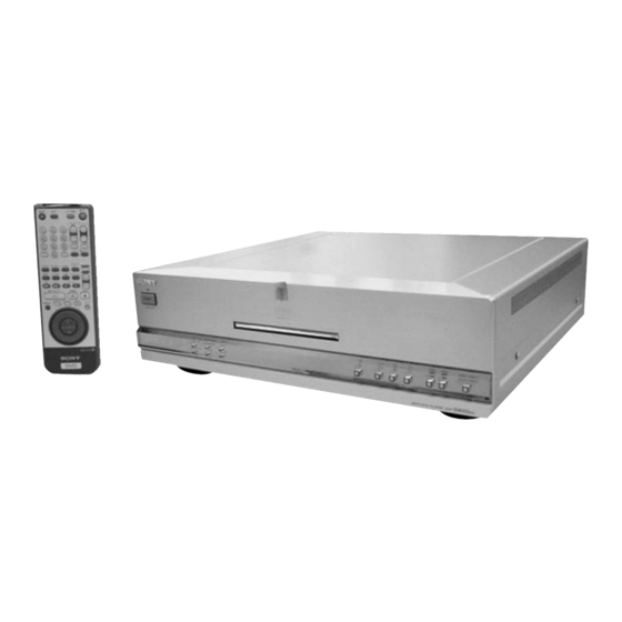
DVP-S9000ES
RMT-D122A/D122E/D122O/D122P
Photo: Gold type
SPECIFICATIONS
Outputs
Jack
Output
Load impedance
type
level
AUDIO OUT
Phono
2 Vrms
Over 10 kilohms
(1, 2)
jacks
(at 50 kilohms)
DIGITAL OUT
Optical
–18 dBm
Wave length: 660 nm
(OPTICAL)
output
connector
DIGITAL OUT
Phono
0.5 Vp-p
75 ohms terminated
(COAXIAL)
jack
Phono
1.0 Vp-p
75 ohms,
VIDEO OUT
jacks
sync negative
S VIDEO OUT
4-pin
Y: 1.0 Vp-p
75 ohms,
mini DIN
C: 0.3 Vp-p
sync negative
(PAL)
75 ohms terminated
(EXCEPT US,
Canadian)
C: 0.286 Vp-p
(NTSC)
COMPONENT
Phono
Y: 1.0 Vp-p
75 ohms,
VIDEO OUT
jacks
P
/C
,
sync negative
B
B
(Y, P
/C
,
P
/C
:
B
B
R
R
±0.35 Vp-p
P
/C
)
75 ohms
R
R
US Model
Canadian Model
AEP Model
UK Model
Australian Model
Chinese Model
Hong Kong Model
General
Power requirements
220
- 240 V AC, 50/60 Hz
120 V AC, 60Hz (EXCETP US, Canadian)
Power consumption
48
W
43 W (EXCEPT US, Canadian)
Dimensions (approx.)
×
×
398 mm (17 × 5 ×
430
126
(w/h/d) incl. projecting parts
Mass (approx.)
12.6 kg (27 lb 12 oz)
Operating temperature
5 ˚C to 35 ˚C (41 ˚F to 95 ˚F)
Operating humidity
25 % to 80 %
Supplied accessories
Check that you have the following items:
• Audio connecting cord (1)
• Video connecting cord (1)
• S-link (Control S) connecting cord (1)
• S video cord (1)
• Power cord (1)
• Remote commander (remote) (1)
• Size AA (R6) batteries (2)
Design and specifications are subject to change without notice.
SACD/DVD PLAYER
11
15
/
in.)
16
Advertisement
Table of Contents

Related Manuals for Sony DVP-S9000ES


Summary of Contents for Sony DVP-S9000ES
-
Page 1: Specifications
DVP-S9000ES RMT-D122A/D122E/D122O/D122P SERVICE MANUAL US Model Canadian Model AEP Model UK Model Australian Model Chinese Model Hong Kong Model Photo: Gold type SPECIFICATIONS Outputs SACD/DVD player General Laser Semiconductor laser Power requirements Signal format system Jack Output Load impedance - 240 V AC, 50/60 Hz... - Page 2 OPERATION. REPLACE THESE COMPONENTS WITH DE FONCTIONNEMENT. NE REMPLACER CES COM- SONY PARTS WHOSE PART NUMBERS APPEAR AS POSANTS QUE PAR DES PIÈCES SONY DONT LES SHOWN IN THIS MANUAL OR IN SUPPLEMENTS PUB- NUMÉROS SONT DONNÉS DANS CE MANUEL OU LISHED BY SONY.
-
Page 3: Table Of Contents
TABLE OF CONTENTS Section Title Page Section Title Page Service Note ................5 VP-52 (PROGRESSIVE) Schematic Diagram .... 4-51 VP-52 (SGRAM) Schematic Diagram ......4-53 VP-52 (D/A CONVERTER) Schematic Diagram ..4-55 GENERAL VP-52 (VIDEO BUFFER) Schematic Diagram ... 4-57 AU-226, CO-26 Printed Wiring Boards ....... -
Page 4: Section Title Page
Section Title Page Checking RGB Output B (AEP, UK Model) ....7-4 Checking S Video Output S-C ........7-4 7-4. Adjustment Related Parts Arrangement ..... 7-6 REPAIR PARTS LIST 8-1. Exploded Views ............8-1 8-1-1. Case Assembly ............8-1 8-1-2. Chassis Assembly ..........8-2 8-1-3. -
Page 5: Service Note
SERVICE NOTE 1. DISASSEMBLY • This set can be disassembled in the order shown below. Top Case (Page 2-1) PS-436/437/438/439 Front Panel Mechanism Deck MB-91 Board AU-226 Board Board (Page 2-1) (Page 2-2) (Page 2-1) (Page 2-2) (Page 2-2) FL-114 Board TK-58 Board Loading Assembly Base Assembly... -
Page 6: General
If there are If you have any questions or pr oblems concerning your questions regarding your Sony TV set’s compatibility with this • Do not use irregularly shaped discs such as heart- or player, please consult your nearest Sony dealer. -
Page 7: Getting Started
Getting Unpacking TV Hookups Started This connection is for listening to the sound through TV Check that you have the following items: Required cords speakers (L: left, R: right). Refer to the instructions • Audio connecting cord (1) Audio connecting cord (supplied) (1) supplied with the component to be connected. -
Page 8: Channel Surround Hookups
5.1 Channel Surround Hookups With DVDs which contain DTS or Dolby Digital sound, Setups for the player Required cords Setups for the player you can enjoy the surround sound while producing the Audio connecting cord (supplied) (1) Some setup adjustments are necessary for the player Some setup adjustments are necessary for the player effect of being in a movie theater or a concert hall using a depending on the components to be connected. -
Page 9: Playing Discs
Playing Discs Operation Sound Effects Playing Discs (Sound Feedback) To return to the previous screen The player beeps when the following operations are Depending on the DVD or VIDEO CD, some Press ORETURN. performed. This chapter describes how to play a operations may be different or restricted. - Page 10 Playing at Various Speeds/Frame by Frame Playing at Various Speeds/ Frame by Frame When you play back a SACD/CD/VIDEO CD Additional operations To play the disc frame by frame (Jog mode) During playback Using the click shuttle and the JOG button/indicator, you can play back a DVD/SACD/CD/VIDEO CD at various FF2M Fast forward (faster than “FF1M”) speeds or frame by frame.
-
Page 11: Using The Front Panel Display
Using the Front Panel Display Playing VIDEO CDs with PBC Functions (PBC Playback) When playing VIDEO CDs with PBC (Play Back Control) To go back to the menu You can check information about the disc, such as the total Checking the remaining time functions (Ver. -
Page 12: Control Menu Item List
Control Menu Item List Press ENTER. To cancel while making a selection TITLE (DVD only) (page 31)/ VIDEO CONTROL (DVD and VIDEO CD Press O RETURN. SCENE (VIDEO CD during PBC playback only) (page 38) 1 2 ( 2 7 ) PLAY 1 8 ( 3 4 ) To display other items... -
Page 13: Labeling The Disc
Labeling the Disc Labeling the Disc Input the time code using the number buttons, You can label discs so that the label appears on your TV Select “TIME/MEMO” and press ENTER. Repeat steps 3 and 4 to input other characters. then press ENTER. -
Page 14: Video Control
Changing the Angles Displaying the Subtitles Changing the Angles Adjusting the Picture (VIDEO CONTROL) With DVDs on which subtitles are recorded, you can turn With DVDs on which various angles (multi-angles) for a Select the angle number using the number buttons You can adjust the playback image of a DVD to match the the subtitles on and off whenever you want while playing scene are recorded, you can change the angles. -
Page 15: Checking The Play Information
Checking the Play Information Press M / m to select areas of an image. Press ENTER. You can check information such as the bit rate or the disc Displays of each item The upper region adjusts the dark areas and the lower “VIDEO CONTROL”... -
Page 16: Playing Repeatedly (Repeat Play)
Creating Your Own Program (Program Play) Creating Your Own Program (Program Play) Press , . x When playing a VIDEO CD or SACD/CD The program remains even after Program Play ends You can play the contents of the disc in the order you When you press H, you can play the same program again. -
Page 17: Settings And Adjustments
Settings and Repeating a Specific Portion (A–B Repeat) Using the Setup Display Adjustments You can play a specific portion of a title, chapter or track During playback, when you find the starting point repeatedly. This function is useful when you want to do (point A) of the portion to be played repeatedly, Using the setup display, you can do the initial setup, such things as memorize lyrics. -
Page 18: Language Setup
Setting the Display Language or Sound Track Settings for the Display (SCREEN SETUP) (LANGUAGE SETUP) “LANGUAGE SETUP” allows you to set various x AUDIO “SCREEN SETUP” allows you to set the display according 4:3 LETTER BOX languages for the on-screen display or sound track. Selects the language for the sound track. -
Page 19: Audio Setup
Custom Settings (CUSTOM SETUP) The following settings are stored in memory by the x When you have already registered a password Select a geographic area as the playback limitation Limiting Playback by Children (Parental Playback Memory function. The display for confirming the password appears. Skip level standard using M/ m , then press ENTER. - Page 20 06,18 WIDE MODE* Switch to or from the wide mode of a format, it also increases the clarity and sharpness which is Sony Wide TV. based conversion method makes borrows adjacent field unique to Progressive format images. Daytron Radio Shack 05,14 information to fill in the missing information.
-
Page 21: Additional Information
, The player is in pause mode or in Slow-motion Insert a disc. , Multilingual tracks are not recorded on the DVD. , Contact your Sony dealer or local authorized Sony Play mode. Press H to return to normal play , Insert the disc correctly with the playback side , Changing the language for the track is prohibited service facility. -
Page 22: Language Code List
Exx (xx is any number) 1226 Croatian 1363 Burmese 1051 Aymara 1525 Telugu , When you contact your Sony dealer or local authorized Sony service facility, give the 5-character service number. (example: E:61:10) 1052 Azerbaijani 1229 Hungarian 1365 Nauru 1527... - Page 23 WIDE MODE button (65) Opens or closes the disc tray. 3 Number buttons Changes the wide mode of the Sony TV. Selects and executes the items or settings. wf VIDEO ON/OFF button (20) 4 CLEAR button (45 through 49) Turns on/off the video output.
-
Page 24: Disassembly
DVP-S9000ES SECTION 2 DISASSEMBLY Note: Follow the disassembly procedure in the numerical order given. 2-1. TOP CASE REMOVAL 2-3. FL-114 BOARD REMOVAL 4 Top case 1 Connector 1 Three screws (CN101) (BV/CU) 4 FR-172 board 3 Two screws 3 Screw (BV3 ×... -
Page 25: Ps-436/437/438/439 Board Removal
2-5. PS-436/437/438/439 BOARD 2-7. MECHANISM DECK REMOVAL REMOVAL 3 Three screws 9 PS-436 board (US, Canadian) (BVTP3 × 12) PS-438 board (EXPECT US, Canadian) 4 Mechanism deck 7 PS-437 board (US, Canadian) 2 Two connectors PS-439 board (CN307, 309) 2 Two flat cables (EXCEPT US, Canadian) (CN403, 404) 3 Two screws... -
Page 26: Loading Assembly Removal
2-9. LOADING ASSEMBLY REMOVAL 2-10. OPTICAL PICK-UP REMOVAL 2 Three step screws 1 Three hexagon socket bolts (3 × 10) 3 Optical pick-up 2 MD cover 4 Screw (B3 × 8) 7 Loading assembly 6 Tray assembly 1 Two flexible boards 5 Slide the slider (R) (CN001, 002) and lift up the loading... -
Page 27: Internal View
2-12. INTERNAL VIEW DC motor (loading) 1-763-397-21 KHM-220AAA service assembly A-6062-397-A... -
Page 28: Circuit Boards Location
2-13. CIRCUIT BOARDS LOCATION PS-437 (US, Canadian) PS-436 (US, Canadian) PS-439 (EXCEPT US, Canadian) PS-438 (EXCEPT US, Canadian) (POWER SUPPLY) (POWER SUPPLY) CO-26 AC-113 (US, Canadian) (DIGITAL OUT COAXIAL JACK) AC-114 (EXCEPT US, Canadian) (STANDBY) AU-226 BZ-1 (AUDIO) (BUZZER) ER-11 (AEP, UK) SW-344 (EURO AV) (POWER SWITCH) -
Page 29: Block Diagrams
DVP-S9000ES SECTION 3 BLOCK DIAGRAMS 3-1. OVERALL BLOCK DIAGRAM MB-91 BOARD (SEE PAGE 4-19 to 4-42) IC902 16M DRAM VP-52 BOARD SACD RF (SEE PAGE 4-47 to 4-58) IC901 SDATAL, SDATAR PRAWN RY401, 402 BUFFER/ COMPONENT ASDATA3, SPDIF1, SELECTOR IC106... -
Page 30: Rf/Servo Block Diagram
DVP-S9000ES 3-2. RF/SERVO BLOCK DIAGRAM IC001 r; (DVD play) IC001 r; (CD play) IC404 ws (DVD play) IC404 ws (CD play) 50 mV/DIV 50 ms/DIV 200 mV/DIV 50 ms/DIV 50 mV/DIV 50 ms/DIV 200 mV/DIV 50 ms/DIV IC001 1 (DVD play) -
Page 31: Signal Process 1 Block Diagram
DVP-S9000ES 3-3. SIGNAL PROCESS 1 BLOCK DIAGRAM MB-91 BOARD (2/8) (SEE PAGE 4-19, 21, 27, 41) IC901 qf XWCK MSCK SYSTEM XWRFD WRFD MSDI CONTROL SYSTEM MSLT XMSLAT IC901 5 MSDO (SEE PAGE 3-13) CONTROL SAREQ XSRQ MCKI 512 FSSA (SEE PAGE 3-14) DVD: 3.3 Vp-p (24.58 MHz) -
Page 32: Signal Process 2 Block Diagram
DVP-S9000ES 3-4. SIGNAL PROCESS 2 BLOCK DIAGRAM MB-91 BOARD (3/8) (SEE PAGE 4-35 to 4-40) IC804, 805 16M SDRAM 124 125 157 – 160 143 144 127 128 162 – 165 146 147 130 131 167 168 149 151 133 134... -
Page 33: Video 1 Block Diagram
DVP-S9000ES 3-5. VIDEO 1 BLOCK DIAGRAM IC107 4 IC106 wj MB-91 BOARD (4/8) VP-52 BOARD (1/2) (SEE PAGE 4-39) (SEE PAGE 4-47 to 4-56) Q116 BUFFER 5.1 Vp-p (27 MHz) 3.5 Vp-p (27 MHz) IC104 IC105 IC107 IC108 Q104 Q110... -
Page 34: Video 2 Block Diagram
DVP-S9000ES 3-6. VIDEO 2 BLOCK DIAGRAM IC406 7 VP-52 BOARD (2/2) MB-91 BOARD (5/8) (SEE PAGE 4-47, 55, 57) (SEE PAGE 4-39) RY402 1.5 Vp-p (H) IC406 (1/2) IC406 (2/2) J403 Q420 MUTE IC405 (1/2) IC405 (2/2) J404 VIDEO 1... -
Page 35: System Control Block Diagram
DVP-S9000ES 3-7. SYSTEM CONTROL BLOCK DIAGRAM MB-91 BOARD (6/8) (SEE PAGE 4-29 to 4-34) IC105 IC103 INTERFACE 1M SRAM 16M FLASH CONTROL (SEE PAGE 3-17) XFRRST IC202 16M NAND FLASH HA0 – 21 SIGNAL +3.3V PROCESS 1 (SEE PAGE 3-5) IC107 HD0 –15... -
Page 36: Audio Block Diagram
DVP-S9000ES 3-8. AUDIO BLOCK DIAGRAM IC105 rf IC105 ta DVD: 3.2 Vp-p (6.14 MHz) DVD: 3.2 Vp-p (3.07 MHz) CD: 3.2 Vp-p (5.64 MHz) CD: 3.2 Vp-p (2.82 MHz) MB-91 BOARD (7/8) AU-226 BOARD (SEE PAGE 4-41) (SEE PAGE 4-63, 65) -
Page 37: Interface Control Block Diagram
DVP-S9000ES 3-9. INTERFACE CONTROL BLOCK DIAGRAM FL-114 BOARD D203 (SEE PAGE 4-79, 81) VIDEO OFF D205 V OFF LED DIGITAL OFF D204 FL OFF D AU LED D206 FL OFF LED SACD D207 PROGRESSIVE S CD LED IC206 PROG LED... -
Page 38: Power 1 Block Diagram
DVP-S9000ES 3-10. POWER 1 BLOCK DIAGRAM AU-226 BOARD SW-344 BOARD AC-113/114 BOARD AEP, UK (SEE PAGE 4-63, 65) (SEE PAGE 4-91) (SEE PAGE 4-91) IC353 CN352 RY101 T901 B401 CN102 CN104 F101 POWER D301, 314 PS303 AC SW IC302 Q307... -
Page 39: Power 2 Block Diagram
DVP-S9000ES 3-11. POWER 2 BLOCK DIAGRAM PS-437/439 BOARD VP-52 BOARD (SEE PAGE 4-101) (SEE PAGE 4-47 to 4-58) CN201 CN102 IC402 V+SW7V IC401 CN206 +5V REG Q202 IC202 V+5V IC109 +5V REG IC106 +5V REG Q203 IC203 V–5V IC102 IC104 –5V REG... -
Page 40: Printed Wiring Boards And Schematic Diagrams
DVP-S9000ES SECTION 4 PRINTED WIRING BOARDS AND SCHEMATIC DIAGRAMS THIS NOTE IS COMMON FOR PRINTED WIRING For schematic diagram: • Caution when replacing chip parts. BOARDS AND SCHEMATIC DIAGRAMS. New parts must be attached after removal of chip. (In addition to this, the necessary mote is printed Be careful not to heat the minus side of tantalum capacitor, in each block.) -
Page 41: Frame Schematic Diagram
DVP-S9000ES 4-1. FRAME SCHEMATIC DIAGRAM FRAME (1) SCHEMATIC DIAGRAM AC-113 BOARD VP-52 BOARD SW-344 BOARD CN102 AC-114 BOARD B401 CN101 CN102 AC OUT AC IN AC OUT HARNESS AC IN (PV-129) CN106 FAIL-P P.CONT EVER+5V CN104 AC SW CN105 AC SW... -
Page 42: Frame (2) Schematic Diagram
DVP-S9000ES FRAME (2) SCHEMATIC DIAGRAM PS-437 BOARD CN201 AEP,UK CO-26 BOARD B501 CN353 VP-52 BOARD ER-11 BOARD AU-226 BOARD CN352 CN901 CN301 R-CORE TRANS CNJ901 AUDIO GND(E) VMUTEOC VMUTEOC V_IN WIDE WIDE V_OUT RGBSEL RGBSEL GND(E) GND(E) BLANKING_IN MS-59 BOARD... -
Page 43: Digital Out Coaxial Jack)
DVP-S9000ES 4-2. PRINTED WIRING BOARDS AND SCHEMATIC DIAGRAMS There are a few cases that the part isn't mounted in this model is printed on this diagram. TK-58 (RF/SERVO) PRINTED WIRING BOARD – Ref. No.: TK-58 board; 1,000 series – TK-58 BOARD (SIDE A) - Page 44 DVP-S9000ES RF/SERVO TK-58 4-10...
- Page 45 DVP-S9000ES TK-58 (RW GAIN CONTROL) SCHEMATIC DIAGRAM • See page 4-7 for printed wiring board. – Ref. No.: TK-58 board; 6,000 series – TK-58 BOARD (1/2) NO MARK:DVD/CD PLAY CN001 N.C. DVD/CD LD MODULE R002 R145 R144 DVD/CD R152 PD IC C004 0.1u...
- Page 46 DVP-S9000ES TK-58 (RF AMP) SCHEMATIC DIAGRAM • See page 4-7 for printed wiring board. – Ref. No.: TK-58 board; 6,000 series – • Waveforms 1 IC001 1 (DVD play) 6 IC001 r; (CD play) 200 mV/DIV 50 ns/DIV 200 mV/DIV 50 ms/DIV...
- Page 47 DVP-S9000ES MB-91 (SIGNAL PROCESS/SERVO) PRINTED WIRING BOARD – Ref. No.: MB-91 board; 1,000 series – There are a few cases that the part isn't mounted in this model is printed on this diagram. MB-91 BOARD (SIDE A) CN101 CN102 CN104...
- Page 48 DVP-S9000ES MB-91 BOARD (SIDE B) IC103 IC105 IC202 IC301 IC302 IC306 IC401 IC402 IC403 IC406 IC601 IC603 IC604 IC702 IC804 IC805 IC806 IC902 IC903 IC904 Q402 SIGNAL PROCESS/SERVO MB-91 4-17 4-18...
- Page 49 DVP-S9000ES MB-91 (AV DECODER) SCHEMATIC DIAGRAM • See page 4-15 for printed wiring board. – Ref. No.: MB-91 board; 1,000 series – NO MARK:DVD/CD PLAY D:DVD PLAY MB-91 BOARD (1/12) C:CD PLAY *:IMPOSSIBLE TO MEASURE THE VOLTAGE AT THE MARKED POINTS.
- Page 50 DVP-S9000ES MB-91 (SDRAM) SCHEMATIC DIAGRAM • See page 4-15 for printed wiring board. – Ref. No.: MB-91 board; 1,000 series – • Waveforms 6 IC602 <zc,> 1 IC602 qg SIGNAL PATH MB-91 BOARD (2/12) NO MARK:DVD/CD PLAY D:DVD PLAY VIDEO...
- Page 51 DVP-S9000ES MB-91 (SERVO DSP) SCHEMATIC DIAGRAM • See page 4-15 for printed wiring board. – Ref. No.: MB-91 board; 1,000 series – MB-91 BOARD (3/12) NO MARK:DVD/CD PLAY D:DVD PLAY C:CD PLAY CN403 MIRR MIRR SSDFCTI SSDFCTI JL428 TK-58 BOARD (2/2) CN003 3.3V...
- Page 52 DVP-S9000ES MB-91 (DRIVE) SCHEMATIC DIAGRAM • See page 4-15 for printed wiring board. – Ref. No.: MB-91 board; 1,000 series – • Waveforms 1 IC404 og MB-91 BOARD (4/12) JL430 STCK2 C455 R002 0.01u SEMU0 SEMU1 C456 0.1u R012 R013 C457 3.2 Vp-p (27 MHz)
- Page 53 DVP-S9000ES MB-91 (ARP3) SCHEMATIC DIAGRAM • See page 4-15 for printed wiring board. – Ref. No.: MB-91 board; 1,000 series – MB-91 BOARD (5/12) A+5V FL304 MB-91 BOARD (8/12) D+3.3V FL303 FL302 C325 100u 6.3V IC302 C305 C306 +3.3V REG 0.1u...
- Page 54 DVP-S9000ES MB-91 (SYSTEM CONTROL) SCHEMATIC DIAGRAM • See page 4-15 for printed wiring board. – Ref. No.: MB-91 board; 1,000 series – MB-91 BOARD (6/12) • Waveforms MB-91 BOARD (6/12) NO MARK:DVD/CD PLAY D:DVD PLAY 6 IC201 td 1 IC201 ol...
- Page 55 DVP-S9000ES MB-91 (ROM/RAM) SCHEMATIC DIAGRAM • See page 4-15 for printed wiring board. – Ref. No.: MB-91 board; 1,000 series – • Waveforms 1 IC102 tf MB-91 BOARD (7/12) R121 R123 470k :AUS 4.7k :AUS AEP,UK 2.2k NO MARK:DVD/CD PLAY 3.3k...
- Page 56 DVP-S9000ES MB-91 (H2GA) SCHEMATIC DIAGRAM • See page 4-15 for printed wiring board. – Ref. No.: MB-91 board; 1,000 series – • Waveforms 1 IC104 7 MB-91 BOARD (8/12) NO MARK:DVD/CD PLAY D:DVD PLAY C:CD PLAY CN104 JL108 R148 JL109...
- Page 57 DVP-S9000ES MB-91 (MIP) SCHEMATIC DIAGRAM • See page 4-15 for printed wiring board. – Ref. No.: MB-91 board; 1,000 series – • Waveforms 1 IC702 if, <z//> SIGNAL PATH MB-91 BOARD (9/12) VIDEO NO MARK:DVD/CD PLAY SIGNAL D:DVD PLAY C:CD PLAY...
- Page 58 DVP-S9000ES MB-91 (OSD) SCHEMATIC DIAGRAM • See page 4-15 for printed wiring board. – Ref. No.: MB-91 board; 1,000 series – • Waveforms 1 IC802 <z,/>, <z,x> MB-91 BOARD (10/12) R837 MB-91 BOARD (11/12) (SEE PAGE 4-39) MB-91 BOARD (7/12)
- Page 59 DVP-S9000ES MB-91 (SDRAM) SCHEMATIC DIAGRAM • See page 4-15 for printed wiring board. – Ref. No.: MB-91 board; 1,000 series – MB-91 BOARD (11/12) CS3X MB-91 BOARD (7/12) CS2X 27M32 MB-91 BOARD (10/12) (SEE PAGE 4-38) IC804 16M SDRAM IC804...
- Page 60 DVP-S9000ES MB-91 (PRAWN) SCHEMATIC DIAGRAM • See page 4-15 for printed wiring board. – Ref. No.: MB-91 board; 1,000 series – MB-91 BOARD (12/12) NO MARK:DVD/CD PLAY D:DVD PLAY C:CD PLAY *:IMPOSSIBLE TO MEASURE THE VOLTAGE AT THE MARKED POINTS.
- Page 61 DVP-S9000ES VP-52 (VIDEO) PRINTED WIRING BOARD – Ref. No.: VP-52 board; 5,000 series – There are a few cases that the part isn't mounted in this model is printed on this diagram. VP-52 BOARD (SIDE A) CN101 Q105 CN102 Q106...
- Page 62 DVP-S9000ES VIDEO VP-52 4-45 4-46...
- Page 63 DVP-S9000ES VP-52 (TBC) SCHEMATIC DIAGRAM • See page 4-43 for printed wiring board. – Ref. No.: VP-52 board; 5,000 series – VP-52 BOARD (1/6) CN103 JL118 JL123 CHECK NO MARK:DVD/CD PLAY D:DVD PLAY FL108 C:CD PLAY C106 IC102 PQ1R50 L103...
-
Page 64: Vp-52 (Video Encoder) Schematic Diagram
DVP-S9000ES • Waveforms VP-52 (VIDEO ENCODER) SCHEMATIC DIAGRAM • See page 4-43 for printed wiring board. – Ref. No.: VP-52 board; 5,000 series – 1 IC106 ta VP-52 BOARD (2/6) VP-52 BOARD(3/6) SIGNAL PATH R186 VP-52 BOARD(3/6,5/6) VENCRST R192 NO MARK:DVD/CD PLAY... -
Page 65: Vp-52 (Progressive) Schematic Diagram
DVP-S9000ES VP-52 (PROGRESSIVE) SCHEMATIC DIAGRAM • See page 4-43 for printed wiring board. – Ref. No.: VP-52 board; 5,000 series – VP-52 BOARD (3/6) NO MARK:DVD/CD PLAY D:DVD PLAY C:CD PLAY *:IMPOSSIBLE TO MEASURE THE VOLTAGE AT THE MARKED POINTS. -
Page 66: Vp-52 (Sgram) Schematic Diagram
DVP-S9000ES VP-52 (SGRAM) SCHEMATIC DIAGRAM • See page 4-43 for printed wiring board. – Ref. No.: VP-52 board; 5,000 series – SIGNAL PATH VP-52 BOARD (4/6) VIDEO SIGNAL CHROMA Y/CHROMA NO MARK:DVD/CD PLAY D:DVD PLAY C:CD PLAY C326 C327 C329... -
Page 67: Vp-52 (D/A Converter) Schematic Diagram
DVP-S9000ES VP-52 (D/A CONVERTER) SCHEMATIC DIAGRAM • See page 4-43 for printed wiring board. – Ref. No.: VP-52 board; 5,000 series – VP-52 BOARD (5/6) NO MARK:DVD/CD PLAY D:DVD PLAY C:CD PLAY V[0] V[0] V[1] V[1] V[2] V[2] V[3] V[3]... -
Page 68: Vp-52 (Video Buffer) Schematic Diagram
DVP-S9000ES VP-52 (VIDEO BUFFER) SCHEMATIC DIAGRAM • See page 4-43 for printed wiring board. – Ref. No.: VP-52 board; 5,000 series – VP-52 BOARD (6/6) NO MARK:DVD/CD PLAY R492 R499 R505 1200 S401 PROGRESSIVE VP-52 BOARD (1/6) INTERLACE SCAN SELECT... - Page 69 DVP-S9000ES AU-226 (AUDIO), CO-26 (DIGITAL OUT COAXIAL JACK) PRINTED WIRING BOARDS – Ref. No.: AU-226 board; 3,000 series, CO-26 board; 1,000 series – There are a few cases that the part isn't mounted in this model is printed on this diagram.
- Page 70 DVP-S9000ES AU-226 BOARD (SIDE B) CN352 DIGITAL D301 D303 D304 D305 D306 D307 D308 D309 D310 D311 D314 IC106 IC107 IC108 E-10 IC109 IC110 C-10 IC111 IC112 C-10 IC113 IC114 B-11 IC301 IC302 IC351 Q104 A-10 Q105 Q303 Q304 Q305...
- Page 71 DVP-S9000ES AU-226 (D/A CONVERTER, DIGITAL FILTER), CO-26 (DIGITAL OUT COAXIAL JACK) SCHEMATIC DIAGRAM • See page 4-59 for printed wiring board. – Ref. No.: AU-226 board; 3,000 series, CO-26 board; 1,000 series – AU-226 BOARD (1/2) CN101 AU-226 BOARD (2/2)
-
Page 72: Current Pulse D/A, Amp) Schematic Diagram
DVP-S9000ES AU-226 (CURRENT PULSE D/A, AMP) SCHEMATIC DIAGRAM • See page 4-59 for printed wiring board. – Ref. No.: AU-226 board; 3,000 series – AU-226 BOARD (2/2) • Waveforms AU-226 BOARD (1/2) 1 IC105 rf 4 IC105 ta (SEE PAGE 4-64) - Page 73 DVP-S9000ES ER-11 (EURO AV) PRINTED WIRING BOARD – Ref. No.: ER-11 board; 2,000 series – There are a few cases that the part isn't mounted in this model is printed on this diagram. – AEP, UK – ER-11 BOARD( SIDE A)
- Page 74 DVP-S9000ES ER-11 BOARD (SIDE B) D902 D903 D904 D905 D906 D908 D910 D915 D917 D918 D919 D920 D921 D922 D923 D924 D926 D927 D929 D930 EURO AV ER-11 4-69 4-70...
-
Page 75: Er-11 (Euro Av1) Schematic Diagram
DVP-S9000ES ER-11 (EURO AV1) SCHEMATIC DIAGRAM • See page 4-67 for printed wiring board. – Ref. No.: ER-11 board; 2,000 series – – AEP, UK – ER-11 BOARD (1/2) NO MARK:DVD/CD PLAY IC901 SIGNAL PATH VIDEO BUFFER VIDEO SIGNAL IC901... -
Page 76: Euro Av2) Schematic Diagram
DVP-S9000ES ER-11 (EURO AV2) SCHEMATIC DIAGRAM • See page 4-67 for printed wiring board. – Ref. No.: ER-11 board; 2,000 series – – AEP, UK – ER-11 BOARD (2/2) NO MARK:DVD/CD PLAY R927 FB901 D902 1SS355TE-17 FB902 D908 HZM6.8ZWA1TL FB903... - Page 77 DVP-S9000ES FL-114 (FUNCTION SWITCH, IF CON) PRINTED WIRING BOARD – Ref. No.: FL-114 board; 2,000 series – There are a few cases that the part isn't mounted in this model is printed on this diagram. FL-114 BOARD (SIDE A) D202...
- Page 78 DVP-S9000ES BZ-1 (BUZZER) PRINTED WIRING BOARD – Ref. No.: BZ-1 board; 2,000 series – There are a few cases that the part isn't mounted in this model is printed on this diagram. PS-437 (US, Canadian) PS-436 (US, Canadian) PS-439 (EXCEPT US, Canadian)
-
Page 79: If Con) Schematic Diagram
DVP-S9000ES FL-114 (IF CON) SCHEMATIC DIAGRAM • See page 4-75 for printed wiring board. – Ref. No.: FL-114 board; 2,000 series – FL-114 BOARD (1/2) ND201 FLUORESCENT INDICATOR TUBE NO MARK:DVD/CD PLAY *:IMPOSSIBLE TO MEASURE THE VOLTAGE AT THE MARKED POINTS. -
Page 80: Led Drive), Bz-1 (Buzzer) Schematic Diagram
DVP-S9000ES FL-114 (LED DRIVE), BZ-1 (BUZZER) SCHEMATIC DIAGRAM • See page 4-75 for printed wiring board. – Ref. No.: FL-114, BZ-1 board; 2,000 series – FL-114 BOARD (2/2) NO MARK:DVD/CD PLAY CN204 XIFRST JL219 XFRRST IFBSY JL220 IFBSY JL221 IFCS... - Page 81 DVP-S9000ES FR-172 (DC-DC CONVERTER, REMOTE COMMANDER RECEIVER) PRINTED WIRING BOARD There are a few cases that the part isn't mounted in this model is printed on this diagram. – Ref. No.: FR-172 board; 4,000 series – FR-172 BOARD (SIDE A)
-
Page 82: Dc-Dc Converter, Remote Commander Receiver) Schematic Diagram
DVP-S9000ES FR-172 (DC-DC CONVERTER, REMOTE COMMANDER RECEIVER) SCHEMATIC DIAGRAM – Ref. No.: FR-172 board; 4,000 series – FR-172 BOARD NO MARK:DVD/CD PLAY IC101 +3.3V REG CN101 C106 FB101 FAIL.P C104 C105 0.1u FAIL.P 0.1u FB102 AC-113/114 BOARD P-CONT CN106 (SEE PAGE 4-92) -
Page 83: Ac-113/114, Sw-344 Printed Wiring Boards
DVP-S9000ES AC-113/114 (STANDBY), SW-344 (POWER SWITCH) PRINTED WIRING BOARDS – Ref. No.: AC-113/114, SW-344 board; 2,000 series – There are a few cases that the part isn't mounted in this model is printed on this diagram. PS-437 (US, Canadian) PS-436 (US, Canadian) - Page 84 DVP-S9000ES AC-113/114 BOARD (SIDE B) CN101 CN102 CN104 CN105 CN106 D101 D102 D103 D105 D106 D107 D108 D109 IC101 Q101 Q102 Q103 AC-113 : 1-678-947- AC-114 : 1-678-950- STANDBY/POWER SWITCH AC-113/114 4-89 4-90...
-
Page 85: Ac-113/114 (Standby), Sw-344 (Power Switch) Schematic Diagram
DVP-S9000ES AC-113/114 (STANDBY), SW-344 (POWER SWITCH) SCHEMATIC DIAGRAM • See page 4-87 for printed wiring board. – Ref. No.: AC-113/114, SW-344 board; 2,000 series – SW-344 BOARD B401 AC OUT S401 C401 2200p POWER AC IN 250V T901 POWER TRANSFORMER... -
Page 86: Loading Motor), Ck-95 (Sensor) Printed Wiring Boards And Schematic Diagram
DVP-S9000ES MS-59 (LOADING MOTOR), CK-95 (SENSOR) PRINTED WIRING BOARDS AND SCHEMATIC DIAGRAM – Ref. No.: MS-59, CK-95 board; 1,000 series – There are a few cases that the part isn't mounted in this model is printed on this diagram. MS-59 BOARD... -
Page 87: Ps-436/438 Printed Wiring Board
DVP-S9000ES PS-436/438 (POWER SUPPLY) PRINTED WIRING BOARD – Ref. No.: PS-436/438 board; 2,000 series – There are a few cases that the part isn't mounted in this model is printed on this diagram. PS-436 : 1-678-948- PS-438 : 1-678-951- PS-437 (US, Canadian) - Page 88 DVP-S9000ES PS-436/438 BOARD (SIDE B) CN307 CN309 D301 D303 D312 D313 D316 D317 D318 IC301 IC303 Q301 PS-436 : 1-678-948- PS-438 : 1-678-951- POWER SUPPLY PS-436/438 4-97 4-98...
-
Page 89: Ps-436/438 (Power Supply) Schematic Diagram
DVP-S9000ES PS-436/438 (POWER SUPPLY) SCHEMATIC DIAGRAM • See page 4-95 for printed wiring board. – Ref. No.: PS-436/438 board; 2,000 series – PS-436/438 BOARD NO MARK:DVD/CD PLAY D303 1SS181-TE85L IC303 +3.3V REG IC303 IC301 PQ30RV31 +4V REG IC301 LM2596T-ADJ 18.8... -
Page 90: Ps-437/439 (Power Supply) Schematic Diagram
DVP-S9000ES PS-437/439 (POWER SUPPLY) SCHEMATIC DIAGRAM • See page 4-103 for printed wiring board. – Ref. No.: PS-437/439 board; 3,000 series – PS-437/439 BOARD D209 D204 1SS181-TE85L 1SS181-TE85L NO MARK:DVD/CD PLAY IC205 IC202 +5V REG +5V REG IC202 IC205 PQ05RD11... -
Page 91: Ps-437/439 Printed Wiring Board
DVP-S9000ES PS-437/439 (POWER SUPPLY) PRINTED WIRING BOARD – Ref. No.: PS-437/439; 3,000 series – There are a few cases that the part isn't mounted in this model is printed on this diagram. PS-437 : 1-678-949- PS-439 : 1-678-952- PS-437 (US, Canadian) - Page 92 DVP-S9000ES PS-437/439 BOARD (SIDE B) CN201 CN203 CN204 CN206 CN207 D201 D202 D203 D204 D205 D206 D207 D208 D209 D210 D211 D212 D213 D214 D215 D216 D217 D219 D220 IC202 IC203 IC204 IC205 IC206 Q202 Q203 Q206 Q207 Q208 PS-437 : 1-678-949-...
-
Page 93: Ic Pin Function Description
DVP-S9000ES SECTION 5 IC PIN FUNCTION DESCRIPTION... - Page 94 5-2 E...
-
Page 95: Test Mode
DVP-S9000ES SECTION 6 TEST MODE 6-1. GENERAL DESCRIPTION ### Syscon Diagnosis ### Diag All Check The Test Mode allows you to make diagnosis and adjustment eas- No. 2 ROM, Model, Region ily using the remote commander and monitor TV. The instructions, diagnostic results, etc. - Page 96 Disconnect flat cables connected to the CN403 and ber. CN404 of MB-91 board. Also, disconnect harness from the CN102. Model Type DVP-S9000ES (US, Canadian) (4-5) ARP Register (IC303) DVP-S9000ES (UK) Data write → read, and accord check DVP-S9000ES (AEP) Error 41: ARP register write, and read data discord...
- Page 97 (5-4) AVdec DREQ (8-8) Euro Model Check (AEP, UK model) Matching check of 5-3 executed via DMA Composite Out EURO-AV Composite video output check AVD color bar command write → Video (EURO-AV Com- (5-5) AVdec Interrupt Data transfer to AVD RAM via DMA → interrupt detec- posite) OUT tion check Error: Not detected.
- Page 98 Check Items List Error Codes List 2. ROM, Model, Region 00: Error not detected (2-2) ROM Revision 30: RAM write/read data discord (2-3) ROM Check Sum 31: EEPROM NG (2-4) Model Type 32: Flash memory clear error (2-5) Region 33: Flash memory write error 34: Flash memory read data discord 3.
-
Page 99: Drive Auto Adjustment
6-4. DRIVE AUTO ADJUSTMENT 1. DVD-SL (single layer) [ENTER] Select , insert DVD single layer disc, and press key, and the adjustment will be made through the following steps, then On the Test Mode Menu screen, press key on the remote com- adjusted values will be written to the EEPROM. - Page 100 2. CD 3. DVD-DL (dual layer) [ENTER] [ENTER] Select , insert CD disc, and press key, and the adjust- Select , insert DVD dual layer disc, and press key, ment will be made through the following steps, then adjusted val- and the adjustment will be made through the following steps, then ues will be written to the EEPROM.
-
Page 101: Drive Manual Operation
4. SACD 6-5. DRIVE MANUAL OPERATION [ENTER] Select , insert SACD disc, and press key, and the adjustment will be made through the following steps, then adjusted On the Test Mode Menu screen, select , and the manual opera- values will be written to the EEPROM. However, if SACD disc is tion menu will be displayed. - Page 102 0. Disc Check Memory Disc Type 1. Disc Type Auto Check 2. DVD SL 12 cm Disc Check 3. DVD DL 12 cm 4. CD 12cm 5. SACD 12 cm 6. DVD SL 8 cm 1. SL Disc Check 7. DVD DL 8 cm 2.
-
Page 103: Mecha Aging
6-6. MECHA AGING Reset SLED TILT Reset the Sled and Tilt to initial posi- tion. ### Mecha Aging ### Turn ON/OFF the laser. Turn ON/OFF the spindle. Press OPEN key Focus Search the focus and turn on the focus. Turn ON/OFF the tracking servo. Sled Turn ON/OFF the sled servo. -
Page 104: Version Information
How to see Emergency History 6-8. VERSION INFORMATION ## Version Information ## IF con. Ver. x. xxx (xxxx) Group SYScon. Ver. x. xxx (xxxx) Model 1: Emergency Code Region 2: Don't Care Servo DSP. Ver. 1. xxxx These codes are used for verification of software designing. 3: Historical order 1 to 9 Exit: RETURN Emergency Codes List... -
Page 105: If Con Self Diagnostic Function
6-10. IF CON SELF DIAGNOSTIC FUNCTION On the Test Mode Menu screen, selecting displays color bars for prog level adjustment. During display of color bars, OSD dis- appears but the menu screen will be restored if pressing any key. 1. FL-114 BOARD (IF CON) TEST MODE The front board test mode is the IF CON self diagnostic mode. - Page 106 2-2. Operation of Auto Self Check When the Self Check mode becomes active at the AC Power ON or by key input, the test display of the following steps (1) to (4) is repeated. (1) FLD and LED all ON (for 5 seconds) (2) MODEL display (for 2 seconds) (3) Version display (for 2 seconds) (4) ROM creation date display (for 2 seconds)
- Page 107 2-3. Each Self Check Function Each Self Check function tests the FLD display, LED display, and key input. Basic, Entry-DD, Step Up-DD IC204: Pin No. (Signal) Input Voltage [V] (AN6) (AN7) Pin ul Pin i; AUDIO 0 – 0.150 EJECT DIRECT 0.467 –...
- Page 108 [PLAY] Key code display (at input of key, Key code: 0Ah) At input of faulty voltage When two keys are pressed 1-3-3. Remote Commander Key Name Display and Key Code Display 1-3-3-1. Transition Keys in Self Check Mode • Mode Select mode with DVD MENU on remote commander •...
- Page 109 2-3-4. Communication Monitoring Display The communication state is monitored and displayed while the key name on the main unit and the remote commander is displayed. When the communication to the System Controller failed, VIDEO CD, DVD, and CD segments turn on. Communication error display (at no key input) Communication error display (at code display without input of the remote commander)
- Page 110 2-3-6. FLD Grid Test Display 2-3-6-1. Transition Keys in Self Check Mode • DVD MENU → RIGHT, LEFT → [TEST GRID] → RETURN 2-3-6-2. Operation and Display Only the first grid of FLD is lit, and the grids are switched over sequentially by entering the RIGHT or LEFT on the remote com- mander.
- Page 111 1-1 2-1 5-7 Dp ANODE CONNECTION VIDEO PB-M TITLE TRACK CHAPT INDEX – – HOUR – – MPEG – – – – D DIG – – TEXT – ANGLE – D EX – – NTSC – REPEA – – – –...
- Page 112 3. TROUBLESHOOTING 3-1. Test Mode is not activated With the set assembled in the front panel, the Test mode does not become active if any button was pressed by any reason.Under this condition, the power is not turned on even in the normal status. (The set is kept in Standby status = Red LED is kept on) Not only the buttons are inactive, but also a signal from remote commander is not accepted.
-
Page 113: Electrical Adjustments
DVP-S9000ES SECTION 7 ELECTRICAL ADJUSTMENT 7-1. POWER SUPPLY CHECK In making adjustment, refer to 7-4. Adjustment Related Parts Arrangement. 1. AC-113 Board Note: During diagnostic check, the characters and color bars can Mode be seen only with the NTSC monitor. Therefore, for diag-... -
Page 114: Adjustment Of System Control
7-2. ADJUSTMENT OF SYSTEM CONTROL 2. S-terminal Output Check <Purpose> Check S-terminal video output. If it is incorrect, pictures will not 1. System Clock 27 MHz Adjustment (VP-52 BOARD) be displayed correctly in spite of connection to the TV with a S- <Purpose>... -
Page 115: Checking Component Video Output R-Y
4. Checking Component Video Output R-Y 6. Progressive Video Output Level Adjustment <Purpose> (VP-52 BOARD) This checks component video output R-Y. If it is incorrect, cor- <Purpose> rect colors will not be displayed when connected to, for instance, This adjustments progressive video output. If it is incorrect, cor- projector. -
Page 116: Checking Rgb Output G
8. Checking RGB Output G (AEP, UK Model) 10. Checking S Video Output S-C <Purpose> <Purpose> This checks RGB output G. If it is incorrect, pictures will not be This checks whether the S-C satisfies the NTSC Standard. If it is displayed correctly in spite of connection to the TV with an EURO not correct, the colors will be too dark or light. -
Page 117: Adjustment Related Parts Arrangement
7-4. ADJUSTMENT RELATED PARTS ARRANGEMENT AC-113 BOARD (Side A) CN106 PS-436 BOARD (Side A) CN307 PS-437 BOARD (Side A) CN201 CN203... - Page 118 VP-52 BOARD (Side A) 27MHz RV401 CT101 IC108 PROG RV102 RV101 LEVEL S LEVEL N LEVEL CN101 7-10 E...
-
Page 119: Repair Parts List
(US, CND) X-3950-875-1 PANEL (AL-B) ASSY, FRONT (US, CND) 1-476-249-31 COMMANDER, STANDARD (RMT-D122P) 4-942-568-01 EMBLEM (NO.5), SONY (US, CND) (AEP, UK) 4-942-568-31 EMBLEM (NO.5), SONY (EXCEPT US, CND) 1-476-249-41 COMMANDER, STANDARD (RMT-D122E) 3-063-212-01 INDICATOR (POWER) (HK, CN) 3-063-215-01 INDICATOR (TOP) -
Page 120: Chassis Assembly
supplied 8-1-2. CHASSIS ASSEMBLY supplied T902 supplied T901 supplied US, CND AEP, UK supplied supplied supplied supplied supplied supplied supplied supplied US, CND supplied supplied The components identified by Les composants identifiés par une mark 0 or dotted line with marque 0 sont critiques pour la mark 0 are critical for safety. -
Page 121: Mechanism Deck Assembly
8-1-3. MECHANISM DECK ASSEMBLY supplied supplied M501 supplied The components identified by Les composants identifiés par une mark 0 or dotted line with marque 0 sont critiques pour la mark 0 are critical for safety. sécurité. Replace only with part number Ne les remplacer que par une pièce specified. -
Page 122: Electrical Parts List
AC-113 AC-114 8-2. ELECTRICAL PARTS LIST NOTE: The components identified by • Due to standardization, replacements in the • Items marked “*” are not stocked since they mark 0 or dotted line with mark parts list may be different from the parts speci- are seldom required for routine service. - Page 123 AU-226 Ref. No. Part No. Description Remark Ref. No. Part No. Description Remark A-6065-580-A AU-226 BOARD, COMPLETE (AEP, UK) C152 1-119-800-11 ELECT 100uF A-6065-588-A AU-226 BOARD, COMPLETE (HK, CN, AUS) C153 1-119-800-11 ELECT 100uF A-6065-593-A AU-226 BOARD, COMPLETE (US, CND) C154 1-115-197-11 ELECT 100uF...
- Page 124 AU-226 Ref. No. Part No. Description Remark Ref. No. Part No. Description Remark C356 1-127-963-21 FILM CHIP 470PF IC111 8-759-443-33 IC OPA2132PA IC112 8-759-443-33 IC OPA2132PA < CONNECTOR > IC113 8-759-573-62 IC OPA2134PA IC114 8-759-573-62 IC OPA2134PA CN101 1-774-863-11 PIN, CONNECTOR (PC BOARD) 8P IC301 8-759-602-01 IC M5220P * CN103...
- Page 125 AU-226 Ref. No. Part No. Description Remark Ref. No. Part No. Description Remark R122 1-247-706-11 CARBON 1/4W R309 1-249-923-11 CARBON 1/4W R123 1-249-504-11 CARBON 1/4W R310 1-249-923-11 CARBON 1/4W R124 1-249-504-11 CARBON 1/4W R311 1-247-764-11 CARBON 1/2W R125 1-249-504-11 CARBON 1/4W R312 1-249-556-11 CARBON...
- Page 126 BZ-1 CK-95 CO-26 ER-11 Ref. No. Part No. Description Remark Ref. No. Part No. Description Remark A-6065-573-A BZ-1 BOARD, COMPLETE C942 1-163-133-00 CERAMIC CHIP 470PF ******************** (Ref.No. 2,000 Series) C943 1-163-133-00 CERAMIC CHIP 470PF C944 1-163-133-00 CERAMIC CHIP 470PF < BUZZER > C945 1-163-133-00 CERAMIC CHIP 470PF...
- Page 127 ER-11 FL-114 Ref. No. Part No. Description Remark Ref. No. Part No. Description Remark FB914 1-414-553-11 FERRITE R951 1-216-081-00 METAL CHIP 1/10W FB915 1-414-553-11 FERRITE < RELAY > FB916 1-414-553-11 FERRITE FB917 1-414-553-11 FERRITE RY901 1-755-184-11 RELAY FB918 1-414-553-11 FERRITE RY902 1-755-184-11 RELAY RY903...
- Page 128 FL-114 FR-172 Ref. No. Part No. Description Remark Ref. No. Part No. Description Remark < IC > R235 1-216-033-00 METAL CHIP 1/10W R236 1-216-025-11 RES-CHIP 1/10W IC201 8-759-710-82 IC NJM2406F-TE2 (US, CND) R238 1-216-097-11 RES-CHIP 100K 1/10W IC202 8-759-710-82 IC NJM2406F-TE2 IC203 8-759-673-34 IC PST7030MT R240...
- Page 129 FR-172 MB-91 Ref. No. Part No. Description Remark Ref. No. Part No. Description Remark < CONNECTOR > A-6065-579-A MB-91 BOARD, COMPLETE (AEP, UK) * CN101 1-564-724-11 PIN, CONNECTOR (SMALL TYPE) 8P A-6065-587-A MB-91 BOARD, COMPLETE (HK) CN102 1-750-189-21 CONNECTOR, BOARD TO BOARD 16P A-6065-591-A MB-91 BOARD, COMPLETE (AUS) A-6065-590-A MB-91 BOARD, COMPLETE (CN) <...
- Page 130 MB-91 Ref. No. Part No. Description Remark Ref. No. Part No. Description Remark C321 1-107-826-11 CERAMIC CHIP 0.1uF C447 1-107-826-11 CERAMIC CHIP 0.1uF C322 1-162-970-11 CERAMIC CHIP 0.01uF C448 1-162-968-11 CERAMIC CHIP 0.0047uF 10% C323 1-162-970-11 CERAMIC CHIP 0.01uF C449 1-162-968-11 CERAMIC CHIP 0.0047uF 10% C324...
- Page 131 MB-91 Ref. No. Part No. Description Remark Ref. No. Part No. Description Remark C706 1-126-607-11 ELECT CHIP 47uF CN105 1-573-290-21 PIN, CONNECTOR (1.5mm) (SMD) 4P C707 1-162-970-11 CERAMIC CHIP 0.01uF (AEP, UK) C708 1-162-970-11 CERAMIC CHIP 0.01uF CN106 1-778-274-11 CONNECTOR, FFC/FPC 13P C709 1-162-970-11 CERAMIC CHIP 0.01uF...
- Page 132 MB-91 Ref. No. Part No. Description Remark Ref. No. Part No. Description Remark FB912 1-216-864-11 METAL CHIP 1/16W IC401 8-759-660-88 IC LA6553-TE-L FB913 1-216-864-11 METAL CHIP 1/16W IC402 8-759-660-88 IC LA6553-TE-L FB914 1-216-864-11 METAL CHIP 1/16W IC403 8-759-338-78 IC BA10324AFV-E2 FB915 1-216-864-11 METAL CHIP 1/16W...
- Page 133 MB-91 Ref. No. Part No. Description Remark Ref. No. Part No. Description Remark R119 1-216-831-11 METAL CHIP 6.8K 1/16W R317 1-216-833-11 METAL CHIP 1/16W (AEP, UK) R319 1-218-855-11 METAL CHIP 2.2K 0.5% 1/16W R120 1-216-827-11 METAL CHIP 3.3K 1/16W R320 1-218-847-11 METAL CHIP 0.5% 1/16W...
- Page 134 MB-91 MS-59 Ref. No. Part No. Description Remark Ref. No. Part No. Description Remark R459 1-216-833-11 METAL CHIP 1/16W R829 1-216-827-11 METAL CHIP 3.3K 1/16W R460 1-216-845-11 METAL CHIP 100K 1/16W R831 1-216-821-11 METAL CHIP 1/16W R462 1-216-833-11 METAL CHIP 1/16W R833 1-216-833-11 METAL CHIP...
- Page 135 PS-436 PS-438 PS-437 PS-439 Ref. No. Part No. Description Remark Ref. No. Part No. Description Remark A-6065-577-A PS-436 BOARD, COMPLETE (US, CND) A-6065-584-A PS-438 BOARD, COMPLETE A-6065-578-A PS-437 BOARD, COMPLETE (US, CND) (EXCEPT US, CND) A-6065-585-A PS-439 BOARD, COMPLETE (AEP, UK) A-6065-589-A PS-439 BOARD, COMPLETE (HK, CN, AUS) *********************** (Ref.No.
- Page 136 PS-439 SW-344 TK-58 Ref. No. Part No. Description Remark Ref. No. Part No. Description Remark D209 8-719-820-05 DIODE 1SS181-TE85L A-6065-566-A TK-58 BOARD, COMPLETE D210 8-719-074-58 DIODE FCH10A10 ********************* (Ref.No. 6,000 Series) D211 8-719-074-58 DIODE FCH10A10 D212 8-719-074-58 DIODE FCH10A10 < CAPACITOR > D213 8-719-074-58 DIODE FCH10A10 D214...
- Page 137 TK-58 VP-52 Ref. No. Part No. Description Remark Ref. No. Part No. Description Remark < COIL > C106 1-126-395-11 ELECT 22uF L001 1-412-031-11 INDUCTOR CHIP 47uH C107 1-126-205-11 ELECT CHIP 47uF 6.3V C108 1-107-826-11 CERAMIC CHIP 0.1uF < TRANSISTOR > C109 1-126-205-11 ELECT CHIP 47uF...
- Page 138 VP-52 Ref. No. Part No. Description Remark Ref. No. Part No. Description Remark C306 1-162-970-11 CERAMIC CHIP 0.01uF C433 1-126-205-11 ELECT CHIP 47uF 6.3V C307 1-162-970-11 CERAMIC CHIP 0.01uF C434 1-126-205-11 ELECT CHIP 47uF 6.3V C308 1-162-970-11 CERAMIC CHIP 0.01uF C435 1-135-594-21 ELECT 68uF...
- Page 139 VP-52 Ref. No. Part No. Description Remark Ref. No. Part No. Description Remark FL406 1-234-177-21 FILTER, CHIP EMI (AEP, UK) Q110 8-729-216-22 TRANSISTOR 2SA1162-YG-TE85L FL407 1-234-177-21 FILTER, CHIP EMI (AEP, UK) Q111 8-729-216-22 TRANSISTOR 2SA1162-YG-TE85L < IC > Q112 8-729-216-22 TRANSISTOR 2SA1162-YG-TE85L Q113 8-729-216-22 TRANSISTOR...
- Page 140 VP-52 Ref. No. Part No. Description Remark Ref. No. Part No. Description Remark R122 1-216-833-11 METAL CHIP 1/16W R193 1-216-801-11 METAL CHIP 1/16W R123 1-216-833-11 METAL CHIP 1/16W (AEP, UK) R125 1-216-833-11 METAL CHIP 1/16W R194 1-216-801-11 METAL CHIP 1/16W R126 1-216-857-11 METAL CHIP 1/16W...
- Page 141 VP-52 Ref. No. Part No. Description Remark Ref. No. Part No. Description Remark R416 1-218-829-11 METAL CHIP 0.5% 1/16W R468 1-218-855-11 METAL CHIP 2.2K 0.5% 1/16W R417 1-218-829-11 METAL CHIP 0.5% 1/16W (EXCEPT AEP, UK) R418 1-218-829-11 METAL CHIP 0.5% 1/16W R468 1-218-856-11 RES-CHIP...
- Page 142 Ref. No. Part No. Description Remark Ref. No. Part No. Description Remark 1-757-065-11 CABLE, FLEXIBLE FLAT (FMT-29) M501 1-763-397-21 MOTOR, DC (RF-300FA-12350) (LOADING) 0 T901 1-435-680-11 TRANSFORMER, POWER (AUDIO) (US, CND) 0 T901 1-435-681-11 TRANSFORMER, POWER (AUDIO) (EXCEPT US, CND) 0 T902 1-435-683-11 TRANSFORMER, POWER (VIDEO/SYSCON) (US, CND)
- Page 143 DVP-S9000ES Sony Corporation 2000I0567-1 9-921-778-11 Network Entertainment Group Printed in Japan C 2000. 9 – 220 – Published by Quality Assurance Dept.
Need help?
Do you have a question about the DVP-S9000ES and is the answer not in the manual?
Questions and answers