Table of Contents
Advertisement
Quick Links
Advertisement
Table of Contents

Related Manuals for Winco PSS30/B


Summary of Contents for Winco PSS30/B
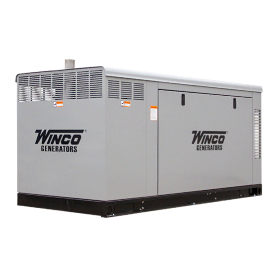
- Page 1 PACKAGE STANDBY SYSTEMS INSTALLATION AND OPERATIONS MANUAL PSS30/B PSS40/E...
-
Page 2: Table Of Contents
Should you experience a problem please follow the “Things DC Electrical Connections To Check” near the end of this manual. The warranty listed INITIAL START-UP in this manual describes what you can expect from WINCO EXERCISER CLOCK should you need service assistance in the future. TROUBLESHOOTING INFORMATION... -
Page 3: Guide To Product Safety
IMPORTANT SAFETY FIRE HAZARD - Natural gas and L.P. present a hazard of possible explosion and/or fire. INSTRUCTIONS Do not smoke or use open flame near the generator set. Keep a fire extinguisher nearby and know its proper use. SAVE THESE INSTRUCTION Fire extinguishers rated ABC by NFPA are appropriate. -
Page 4: Basic Information
• Automatic Transfer Switch Control (Mains Failure) PSS40-4 120/208 • Integrated RS485 PSS40-17 120/240 • Auto Synchronizing PSS40-18 277/480 Additional optional A.T.S. sizes are available to meet specific needs. Contact your local WINCO dealer or the WINCO Sales Department for a quote. 0210-00 Page 2 60706-195... -
Page 5: Dgc-2020 Engine Control Layout
FUNCTIONS temperature, battery voltage, speed, engine load, coolant level DGC-2020 Digital Genset Controllers perform the following (from ECU), ECU specific parameters, and run-time statistics. functions: All metering functions are displayed on the liquid crystal display. Generator Protection and Metering The front panel display begins with the SUMMARY SCREEN. Pressing the Right arrow key will open the MAIN MENU screen. -
Page 6: Specification Table
J - Reset Push-button. This button is pressed to cancel a Repeat sequence 5 through 8 for day, minute, second and settings editing session and discard any settings changes. When DST (Daylight Saving Time. pressed, this button also resets the Breaker Management Pre- To finish clock setting, process - Press ‘K’... -
Page 7: Preparing The Unit
General Information The engine manufacturer has established an excellent worldwide engine service organization; engine service is available from a Note: Roof access panels have been provide to check/fill the nearby authorized dealer or distributor; check the Yellow Pages engine oil and the coolant. Side panels may be removed by of the telephone directory under “engines,”... -
Page 8: Fuel Line Installation
Connect the fuel supply to the inlet of the fuel solenoid (see table FUEL PRESSURE (vapor system) for recommended line size). The pressure at the secondary demand regulator must be four to six ounces psi (per square Correct fuel pressure cannot be stressed enough. The most inch) or 7 to 11 inches W.C. -
Page 9: Lp Liquid Withdrawal
Notice the preceding tables give two (2) different units of measur- When installing or replacing batteries, use the proper group/size ing fuel pressure. The first is with a pressure gauge calibrated in starting battery. The battery should be a Maintenance Free lead ounces per square inch. -
Page 10: Battery Charger/Block Heater Wiring
properly installed, the normal A.T.S. Control and safety systems Never fill the battery above the fill line. Over filling above the will eliminate all paths for feedback. upper level line may cause the electrolyte to overflow, resulting in corrosion to the engine or nearby parts. Immediately wash off To wire the automatic transfer switch into the existing wiring, first any spilled electrolyte following the procedure above. -
Page 11: Dc Electrical Connections
B - Generator Circuit Breaker, This circuit breaker provides The load current carrying wires (L) and (T) must be sized to overload protection for the generator. Your power feeds from the handle the maximum load current without excessive voltage drop. transfer switch will connect to the bottom lugs on the circuit By code, the wire must be heavy enough to handle the full current breaker. - Page 12 B - DC Control Circuit Fuse. The 10 amp DC Circuit Fuse DC Interconnections to the Automatic Transfer Switch protects the 12 volt circuits and engine wiring harness against faults in wiring or control equipment. The fuse also prevents a Two control wires are required between the A.T.S.
-
Page 13: Initial Start-Up
PROCEDURE Depress the “RUN” push-button on the front of the DGC. The engine-generator will crank and start automatically. If the engine fails to start, depress the “stop” push-button and correct the trouble before proceeding. With the engine running smoothly check the no load voltage and frequency on the digital display. -
Page 14: Troubleshooting Information
ATS PANEL WILL NOT TRANSFER TO EMERGENCY TROUBLESHOOTING TABLES SUPPLY (GENERATOR) UNIT WILL NOT CRANK WHEN THE POWER FAILS No AC generator output from generator. Defective transfer switch controller. Digital Genset Controller not in "AUTO". Incorrect voltage or frequecy for the generator. Transfer control switch not in "AUTOMATIC"... -
Page 15: Voltage Regulator Wiring
VOLTAGE REGULATOR WIRING THREE PHASE AND SINGLE PHASE 0210-00 60706-195 Page 13... -
Page 16: 277/480 Volt
0210-00 Page 14 60706-195... -
Page 17: 120/240 Volt
0210-00 60706-195 Page 15... -
Page 18: Dc Schematic - Wiring Diagram
0210-00 Page 16 60706-195... -
Page 19: Outline Drawing
PSS40 OUTLINE DRAWING AND WIRING ENTRANCE PSS30 OUTLINE DRAWING AND WIRING ENTRANCE DIMENSIONS ARE SUBJECT TO CHANGE. ALWAYS OBTAIN A CERTIFIED DRAWING FOR CONSTRUCTION PURPOSES. 0210-00 60706-195 Page 17... -
Page 20: Month Warranty
WINCO’s sole liability, and Purchaser’s sole remedy for a failure under this warranty, shall be limited to the repair of the product. At WINCO’s option, material found to be defective in mate- rial or workmanship under normal use and service will be repaired or replaced. For warranty...
Need help?
Do you have a question about the PSS30/B and is the answer not in the manual?
Questions and answers