Sign In
Upload
Download
Table of Contents
Contents
Add to my manuals
Delete from my manuals
Share
URL of this page:
HTML Link:
Bookmark this page
Add
Manual will be automatically added to "My Manuals"
Print this page
×
Bookmark added
×
Added to my manuals
Manuals
Brands
Intel Manuals
Motherboard
BLKD975XBX2KR
Product manual
Intel BLKD975XBX2KR Product Manual
Product guide
Hide thumbs
1
2
3
4
Table Of Contents
5
6
7
8
9
10
11
12
13
14
15
16
17
18
19
20
21
22
23
24
25
26
27
28
29
30
31
32
33
34
35
36
37
38
39
40
41
42
43
44
45
46
47
48
49
50
51
52
53
54
55
56
57
58
59
60
61
62
63
64
65
66
67
68
69
70
71
72
73
74
75
76
77
78
page
of
78
Go
/
78
Contents
Table of Contents
Bookmarks
Table of Contents
Canadian Department of Communications Compliance Statement
Fcc Declaration of Conformity
Revision History
Document Layout
Intended Audience
Use Only for Intended Applications
Box Contents
Table of Contents
Desktop Board Features
Related Links
Supported Operating Systems
Tables
Desktop Board Components
Desktop Board D975XBX2 Components
Figures
Main Memory
Processor
Intel 975X Express Chipset
Memory Operating Frequencies
Audio Subsystem
Input/Output (I/O) Controller
LAN Subsystem
LAN Subsystem Software
RJ-45 LAN Connector Leds
RJ-45 10/100/1000 Gigabit Ethernet LAN Connector Leds
Hi-Speed USB 2.0 Support
Enhanced IDE Interface
Serial ATA
Expandability
Bios
Serial ATA and IDE Auto Configuration
PCI and PCI Express* Auto Configuration
Security Passwords
Chassis Intrusion
Power Management Features
Acpi
Fan Connectors
Location of Standby Power Indicator
Resume on Ring
Wake from USB
Wake from PS/2* Keyboard/Mouse
PME# Wakeup Support
Onboard Power Button
Speaker
Battery
Real-Time Clock
Location of Onboard Power Button
Installing and Replacing Desktop Board Components
Before You Begin
Installation Precautions
Prevent Power Supply Overload
Observe Safety and Regulatory Requirements
Installing the I/O Shield
Installing and Removing the Desktop Board
Location of Mounting Screw Holes
Installing and Removing a Processor
Installing a Processor
Lift Socket Lever
Lift the Load Plate
Remove the Protective Socket Cover
Remove the Processor from the Protective Processor Cover
Install the Processor
Close the Load Plate
Installing the Processor Fan Heat Sink
Connecting the Processor Fan Heat Sink Cable
Removing the Processor
Connecting the Processor Fan Heat Sink Cable to the Processor Fan Header
Installing and Removing Memory
Dual Channel Memory Configuration Example 1
Dual Channel Memory Configuration Example 2
Dual Channel Memory Configuration Example 3
Installing Dimms
Use DDR2 Dimms
Installing a DIMM
Removing Dimms
Installing and Removing a PCI Express X16 Card
Installing a PCI Express X16 Card
Installing PCI Express Graphics Cards
Installing a PCI Express X16 Card
Removing the PCI Express X16 Card
Connecting the IDE Cable
Connecting the Serial ATA Cable
Connecting Serial ATA Cables
Connecting Internal Headers
Internal Headers
Front Panel Header
Alternate Front Panel Power LED Header
IEEE 1394A Header
Front Panel Header Signal Names
IEEE 1394A Header Signal Names
USB 2.0 Headers
Front Panel Audio Header
Front Panel Audio Header Signal Names
Connecting the Rear Panel USB 2.0 Adapter
Installing an External Serial ATA Adapter
Connecting an External Serial ATA Adapter
Connecting Chassis Fan Cables
Location of Fan Headers
Connecting Power Supply Cables
Other Connectors
Location of Other Connectors
Setting the BIOS Configuration Jumper
Location of the BIOS Configuration Jumper Block
Jumper Settings for the BIOS Setup Program Modes
Clearing Passwords
Back Panel Connectors
Replacing the Battery
Removing the Battery
Bios
Accessing the BIOS Setup Program
Updating the BIOS
Updating the BIOS with the Intel Express BIOS Update Utility
Updating the BIOS with the Iflash Memory Update Utility
Recovering the Bios
4 Configuring for RAID Requires Microsoft Windows* XP
Configuring for RAID Using Intel Matrix Storage Technology
Configuring the BIOS
Creating Your RAID Set
Loading the Intel Matrix Storage Technology RAID Drivers and Software
Setting up a "RAID Ready" System
Configuring for RAID Using Marvell Storage Technology
Configuring the BIOS
Creating Your RAID Set
Loading the Marvell Storage Technology RAID Drivers and Software
A Error Messages and Indicators
BIOS Beep Codes
BIOS Error Messages
Beep Codes
B Regulatory Compliance
Safety Regulations
Place Battery Marking
European Union Declaration of Conformity Statement
Product Ecology Statements
Lead-Free Desktop Board
EMC Regulations
Ensure Electromagnetic Compatibility (EMC) Compliance
Product Certifications
Board-Level Certification Markings
Product Certification Markings
Chassis and Component Certifications
Advertisement
Quick Links
1
Desktop Board Components
2
Processor
Download this manual
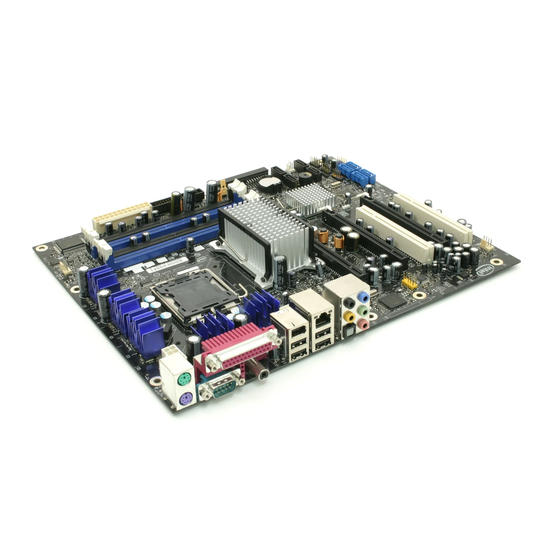
Intel® Desktop Board D975XBX2
Product Guide
Order Number: D63326-005
Table of
Contents
Previous
Page
Next
Page
1
2
3
4
5
Advertisement
Table of Contents
Need help?
Do you have a question about the BLKD975XBX2KR and is the answer not in the manual?
Ask a question
Questions and answers
Related Manuals for Intel BLKD975XBX2KR
Motherboard Intel D975XBX2 - Desktop Board Motherboard Specification
Product specification (106 pages)
Motherboard INTEL D945GCLF Product Manual
(56 pages)
Motherboard INTEL DESKTOP BOARD D955XBK Manual
(94 pages)
Motherboard Intel BLKD915PBLL - LGA775 800FSB 4DDR2 Audio Lan 1394a SATA Raid ATX 4PCI 10Pack Motherboard Technical Product Specification
Product specification (98 pages)
Motherboard Intel BLKD915PGNL - LGA775 800FSB 4DDR Audio Lan SATA ATX 4PCI Technical Product Specification
Product specification (107 pages)
Motherboard Intel BLKD925XBCLK Specification
Desktop board (112 pages)
Motherboard Intel BLKD945GCLF2 Product Manual
Product guide (58 pages)
Motherboard Intel BLKD945GCLF2D Technical Product Specification
Product specification (84 pages)
Motherboard Intel BLKD945GCNL Technical Product Specification
Product specification (90 pages)
Motherboard Intel BLKD945GCPE - LGA775 1066FSB 2DDR2 2GB Audio Video Lan mATX 10Pack Motherboard Technical Product Specification
Product specification (80 pages)
Motherboard Intel BLKD945GNTL - LGA775 1066 800FSB 4DDR2 A/V Lan SATA ATX 10Pack Motherboard Technical Product Specification
Product specification (94 pages)
Motherboard Intel BLKD945GPMLKR Technical Product Specification
Product specification (94 pages)
Motherboard Intel BLKD945GSEJT Product Manual
Product guide (72 pages)
Motherboard Intel BLKD945GTPL Technical Product Specification
Product specification (92 pages)
Motherboard Intel BLKD946GZABL Technical Product Specification
Product specification (90 pages)
Motherboard Intel BLKD946GZISSL - CONROE LGA775 1066 800FSB DR2 A/V Lan SATA mATX 10Pack ACTIVE Motherboard Technical Product Specification
Product specification (88 pages)
This manual is also suitable for:
Boxd975xbx2kr
D975xbx2kr - core 2 duo ready socket 775 atx motherboard
D975xbx2
Table of Contents
Print
Rename the bookmark
Delete bookmark?
Delete from my manuals?
Login
Sign In
OR
Sign in with Facebook
Sign in with Google
Upload manual
Upload from disk
Upload from URL


Need help?
Do you have a question about the BLKD975XBX2KR and is the answer not in the manual?
Questions and answers