Table of Contents
Advertisement
Quick Links
Advertisement
Table of Contents

Subscribe to Our Youtube Channel
Related Manuals for CPS SC14KTL-DO/US-208


Summary of Contents for CPS SC14KTL-DO/US-208
- Page 1 CPS SC Series Grid-tied PV Inverter CPS SC14KTL-DO/US-208 Ver 1.1...
- Page 2 CHINT POWER SYSTEMS AMERICA CO., LTD. Address: 700 International Parkway Web: www.chintpower.com/na Suite 102 Email: americasales@chintpower.com Richardson TX 75081 Service Hotline: 855-584-7168 SHANGHAI CHINT POWER SYSTEMS CO., LTD. All rights reserved. Specifications and designs included in this manual are subject to change without notice. CHINT POWER 2013/09-MKT PN: 9.0020.0117B0...
-
Page 3: Table Of Contents
Table of Contents Before You Start… ..................1 Chapter 1 IMPORTANT SAFETY INSTRUCTIONS ........2 Chapter 2 Overview .................. 5 2.1 Inverter for grid-tied PV systems ........... 5 2.2 Product features ................5 2.3 Circuit structure design ..............6 2.4 Appearance description ..............7 Chapter 3 Installation ................ -
Page 5: Before You Start
This manual contains important information regarding installation and safe operation of this unit. Be sure to read this manual carefully before using. Thanks for choosing this CPS Grid-tied PV Inverter. This PV Inverter is a high performance and highly reliable product specifically designed for the North American Solar market. -
Page 6: Chapter 1 Important Safety Instructions
Chapter 1 IMPORTANT SAFETY INSTRUCTIONS (SAVE THESE INSTRUCTIONS) Please read this user manual carefully before product installation. CPS reserves the right to refuse warranty claims for equipment damage if the user fails to install the equipment according to the instructions in this manual. - Page 7 Markings on the product HIGH VOLTAGE: The product works with high voltages. All work on the product must only be performed as described in this document. HOT SURFACE: The equipment is designed to meet international safety standards, but surfaces can become hot during operation. Do not touch the heat sink or peripheral surfaces during or shortly after operation.
- Page 8 Do not connect the AC output of this equipment directly to any private AC power equipment. CAUTION: CPS SC14KTL-DO inverter is approx 64kg (≈141 pounds). Please ensure the mounting is properly installed before hanging the the inverter on the bracket.
-
Page 9: Chapter 2 Overview
Chapter 2 Overview 2.1 Inverter for grid-tied PV systems CPS SC14KTL-DO/US-208 inverter is suitable for use with various commercial rooftop systems and distributed power station systems. Normally, the system mainly consists of PV modules, DC power distribution equipments, PV inverter and AC power distribution equipments (Figure 2-1). The inverter converts the DC from PV modules to AC with the same frequency and phase as the AC grid. -
Page 10: Circuit Structure Design
2.3 Circuit structure design The basic schematic diagram of CPS SC14KTL-DO/US-208 is shown in Figure 2-2. The input DC passes through surge protection circuitry, DC EMI filter, and the boost circuit to achieve maximum power tracking and boost up voltages. The inverter converts the DC energy to 3-phase AC energy. The high frequency components of AC voltage are removed with a line filter. -
Page 11: Appearance Description
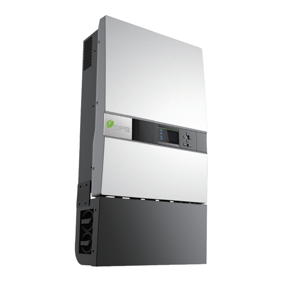
2.4 Appearance description Figure 2-3 Appearance sketch of CPS SC14KTL-DO/US-208 Description of main items of CPS SC14KTL-DO/US-208 (See Figure 2-3): 1. LCD key buttons: operate the functions and change settings of inverter 2. LCD display: indicates data 3. LED indicator lights: indicate the status of inverter 4. -
Page 12: Chapter 3 Installation
Below is the installation instruction of the inverter. Please read carefully and install the product step-by-step. Before installation, please check that the following items are included in the package: Table 3-1 Main items Q’ty Item Note SC14KTL-DO/US-208 Grid-tied PV inverter Mounting bracket Installation and operation manual Warranty card contains necessary... -
Page 13: Recommendation Before Installation
Do not install the inverter near the electromagnetic source which can compromise the normal operation of electronic equipment; 3.2 Mechanical installation (1) Dimensions The dimensions of CPS SC14KTL-DO/US-208 inverter are shown in Figure 3-1. - Page 14 8.46in 21.42in 215mm 544mm Figure 3-1 Dimensions of CPS SC14KTL-DO/US-208 (2) Installation method Make sure that the mounting structure (wall, rack, etc) is suitable to support the inverter weight. Follow the mounting guidelines below: (a) If the location permits, install the inverter vertically.
- Page 15 backward by Max. 15° . (c) Do NOT mount the inverter forwards. (d) Do NOT mount the inverter in a horizontal position. (e) Do NOT mount the inverter upside down. Figure 3-2 Mounting the inverter properly (3) Space required for inverter mounting on the wall (see Figure 3-3) The distances between the inverter and the surrounding objects should meet the following conditions: two sides from the walls ≥300mm (11.81in.);...
- Page 16 distance ≥300mm (11.81in.); bottom distance ≥600mm (23.62in.); the minimum spacing between two inverters in parallel ≥600mm (11.81in.). Figure 3-3 Inverter mounting dimensions (4) Secure the bracket with bolts through the mounting holes and install the inverter: (a) Mark the 6 bolt holes for mounting the bracket as shown in Figure 3-4;...
- Page 17 Figure 3-4 Bracket mounting dimensions (b) Drill holes at the marked positions with a diameter of 0.4in. drill and put the 6 expansion bolts into the holes; (c) Take the mounting bracket out of the package and secure the bracket on the wall with the 6 nuts in pair as shown in Figure 3-5;...
- Page 18 Figure 3-5 Positions of bolt holes on the bracket (d) Screw off the bolts and remove the two panels on both sides of the inverter as shown in Figure 3-6; Figure 3-6 Removal of panels before mounting inverter (e) Two people grab at the position on each side (see Figure 3-7a), lift up the inverter and then hang it on the bracket (see Figure...
- Page 19 3-7b~c). Make sure the inverter is securely fixed on the bracket; Hand Grab Figure 3-7a Mounting inverter on the bracket Figure 3-7b Mounting inverter on the bracket...
- Page 20 Figure 3-7c Mounting inverter on the bracket (f) Put the two removed panels back and secure them with 4 M4*12 bolts on each side, as shown in Figure 3-8. Figure 3-8 Securing panels on both sides...
-
Page 21: Electrical Installation
3.3 Electrical installation Inverter cable terminals of CPS SC14KTL-DO/US-208 are shown in Figure 3-9: Figure 3-9 Inverter cable terminals Position Connection entry Knockout holes for DC input cables Knockout hole for AC output and ground cables Knockout hole for communication cables 3.3.1 DC connection... - Page 22 (a) Strip the skin 0.4 inch off the cables as shown in Figure 3-10: Figure 3-10 Wire stripping of DC input (b) Crimp the terminal as shown in Figure 3-11: Figure 3-11 Terminal crimping of DC input (c) The order of cable connection from left to right is PV1+, PV1-, PV2+, PV2-.
-
Page 23: Ac And Ground Connection
3.3.2 AC and ground connection The following describes how to connect the AC output and grounding cables between the inverter and the public power grid: (1) Use the recommended cables: L1 (Line 1), L2 (Line 2), L3 (Line 3), Neutral and Gnd (Equipment grounding conductor):8AWG copper cored soft cables (2) Cable making for AC output: (a) Strip the skin 0.4 inch off the cables as shown in Figure 3-14:... - Page 24 (b) Crimp the terminal with the ring terminal in the accessory kit as shown in Figure 3-17(a) or (b): Figure 3-17(a) Diagram for terminal crimping of grounding conductor Figure 3-17(b) Diagram for terminal crimping of grounding conductor (3) Connection of AC output and ground cables (a) Connect the L1, L2, L3 and Neutral AC output cables to the corresponding terminals of the socket on the PCB board.
- Page 25 Figure 3-18(a) Diagram of AC output and ground cable connection Figure 3-18(b) Diagram of AC output and ground cable connection...
-
Page 26: Communication Connection
3.3.3 Communication connection 1) Standard RS485 communication There are two RS485 signal ports on the inverter. Shielded cables should be used for communication cables with the maximum length of 3280 feet. (1) The communication of one single local inverter is to connect the RS485 communication bus cable through the RS485-1 or RS485-2 port of the inverter directly. - Page 27 (3) RS485 network connection: When the inverters are monitored via the RS485 communication, the unique RS485 address for each inverter can be set through the LCD interface. Up to 31 inverters can be connected together in the RS485 communication network. The Daisy-chain topology is recommended for the RS485 network connection, as shown in Figure 3-20.
- Page 28 Figure 3-21 Diagram of communication wiring 2) Optional communication card connection The inverter also supports 2 optional communication methods: Ethernet and ZigBee. Each communication card supports firmware upgrade by USB disk. INSTRUCTION: Please remove the communication cables in Figure 3-21 before installing the optional communication card.
- Page 29 Figure 3-22 Install the Ethernet card 2. Crimp the communication cable, as shown below: Figure 3-23 Diagram of Ethernet wiring Table 3-4 Ethernet wiring requirement Color White orange Orange White green Blue White blue...
- Page 30 Green White brown Brown 3. Connect the communication cables as figure 3-24(a) or (b): Figure 3-24(a) Cable connection of Ethernet communication...
- Page 31 Figure 3-24(b) Cable connection of Ethernet communication The Ethernet card is equipped with an Ethernet port for TCP/IP communication. The factory default IP address is 192.168.1.100. You may check the IP address by the finder.exe software. Use the Web Page function embedded in the Ethernet card to input the effective IP address in the IE address bar, such as //192.168.1.100.
- Page 32 Figure 3-25 Communication port on the Ethernet card b.) Zigbee communication 1. Install the Zigbee card in the wiring box, and fasten the screws, as follows: Figure 3-26 Install the Zigbee card NOTICE: Please install the communication card in the wiring box as per the requirement of ESD to avoid damaging the card.
- Page 33 Figure 3-27 Fix the cable gland 3. Fix the antenna on the bottom of the wiring box. Fasten the two screws and put the antenna cable through the cable gland. (see Figure 3-28). Figure 3-28 Installation of Zigbee antenna...
- Page 34 Figure 3-29 ZigbeeCard 4. The Zigbee card supports wireless network communication. The communication frequency is optional from 2.405GHz—2.480GHz and the visible communication distance reaches up to 6561 feet. The Zigbee communication is an excellent choice for the onsite where the communication cables are inconvenient to pave.
- Page 35 6. Plug the unused holes on the cable gland with waterproof stick, and fasten the cap of the cable gland. Figure 3-31 Plug waterproof stick into the unused hole For more information about CPS monitoring solutions, please visit www.chintpower.com/na or contact our after-sales service center.
-
Page 36: Chapter 4 Operation
Chapter 4 Operation 4.1 Start-up Manual start-up: Manual start-up is required after initial installation or manual (fault) shut-down. Move the cursor from the main operation interface to “4 Setting”. Press ENT and input the password (PAGEUP -> RIGHT -> PAGEDOWN -> LEFT) to access the submenu “1 ON/OFF”. Then move the cursor to “ON”... - Page 37 (2) Normal operation mode: Default indication interface for normal operation of CPS SC14KTL-DO/US-208 is shown in Figure 4-2 (a) and 4-2 (b). The switching time between (a) and (b) is 5 seconds.
-
Page 38: Grid Connection And Power Generation
Power Grid before maintaining and operating the equipment. 4.4 Grid connection and power generation grid connection power generation process SC14KTL-DO/US-208 is automatic. It will check constantly whether AC power grid meets the grid connection and power generation conditions. At the same... -
Page 39: Fault Shutdown
time, it will also check whether the DC input of PV modules is sufficient. The inverter will turn into normal operation mode when both of AC and DC conditions are fulfilled. The inverter will disconnect from the power grid and switch to standby mode when the sunlight is weak and power generation is small. - Page 40 Table 4-1 Troubleshooting Table Definition: Prompt detection of abnormal temperature Possible causes: 1. Temperature Sensor socket connecter has poor contact; 1. TempSensorErr 2. Temperature Sensor is damaged; Recommended solutions: 1. Observe temperature display; 2. Switch off 3-phase working power supply and then reboot the system;...
- Page 41 Definition: Fan (invisible from outside) inside inverter is working abnormally Possible causes: 1. Fan service life has expired; 2. Fan socket connecter has poor contact. 3. IntFanErr Recommended solutions: 1. Observe for 5 minutes and see whether the alarm will be eliminated automatically; 2.
- Page 42 Possible causes: Internal memory has a certain problem Recommended solutions: 1. Observe for 5 minutes and see whether the alarm will be eliminated automatically; 2. Contact after-sales service personnel Definition: Ambient temperature or temperature inside inverter is too high Possible causes: 1.
- Page 43 Possible causes: 1. Grid voltage is abnormal; Power grid breaks down 2. Cable connection between the inverter and the grid is poor; Recommended solutions: 1. Observe for 10 minutes and see whether the alarm will be eliminated automatically; 2. Check whether the grid voltage is within the specified range;...
- Page 44 abnormalities; 4. Contact after-sales service personnel Definition: PV voltage exceeds the specified value Possible causes: PV over-voltage Recommended solutions: PV1(2) 1. Observe for 30 minutes and see whether the VoltOver* alarm will be eliminated automatically; 2. Check whether PV voltage exceeds the specified range;...
- Page 45 2. Grounding is abnormal; 3. Fault inside the inverter Recommended solutions: 1. Observe for 10 minutes and see whether the alarm will be eliminated automatically; 2.. Detect whether the electrical connection is abnormal 3. Contact after-sales service personnel Definition: Insulation impedance of PV positive to ground or PV negative to ground exceeds the specified range Possible causes:...
- Page 46 Internal fault of the inverter Possible causes: Fault occurs inside the inverter Recommended solutions: 1. The inverter can be forced to restart once if it is required by operation and if it is confirmed that there is no other problem; 2.
-
Page 47: Chapter 5 User Interface
Chapter 5 User Interface 5.1 Description of LCD panel The CPS SC14KTL-DO/US-208 LCD panel mainly consists of LCD screen, LED indicator lights, buzzer and 6 keys, as shown in Figure 5-1. Interpretation for the indicator lights is shown in Table 5-1 and function of the keys is shown in Table 5-2. -
Page 48: Operation State
Fast Protective action (light up 0.5s, light flash off 0.5s) Light No fault or power supply not working Table 5-2 Definitions of the keys Description Definition of function Escape key Back/end/mute Enter key Confirm entering the menu/confirm set point Page up in selection menu Down Page down in selection menu Left... -
Page 49: Interface And Menu Functions
inverter. Otherwise, “GRID” will blink until the grid restores to normal. “FAULT” will blink quickly as a fault (except grid abnormality) occurs. “FAULT” will not light off until the fault is eliminated. The light will blink slowly when an alarm occurs. “FAULT” keeps being lighted up when an internal fault occurs. - Page 50 Figure 5-3 Inverter system check ongoing Standby >>>>>> Figure 5-4 Inverter system in standby mode Figure 5-5 Default display interface for normal operation SPICommErr Figure 5-6 Fault indication interface LCD screen will display different mode interfaces based on the operation modes of the inverter.
-
Page 51: Main Operation Interface
grid voltage, instant power, daily generated power and time information under normal operation. The fault information of the most recent / current fault will be indicated on the LCD screen when the inverter is in fault mode. 5.3.2 Main operation interface LCD screen displays “default indication interface”... -
Page 52: Alarm
Yield 23.5kWh MPac 14.1kW 1 Measurements 13.8kW RunT 1.3 h 14.3KW 208.0V 208.9V 208.5V Freq 60.0Hz 38.3A 38.2A 38.3A Tmod 78.2C Tamb 50 C Upv1 381.0V Ipv1 18.8A Upv2 358.0V Ipv2 20.0A Figure 5-8 Operation information indication 5.3.4 Alarm As described before, when faults occur during the normal operation of the inverter, corresponding fault message will be indicated in “2 Alarm”... -
Page 53: History
NoError 2 Alarm EepromErr Protect0010 … Figure 5-9 Alarm / failure information 5.3.5 History Move the cursor to “3 History” in the main interface. Press ENT to check the history information, as shown in Figure 5-10. There are 4 submenus in “3 History”... -
Page 54: System Setup
NoError 1.St2010.12.15 20:50 SPI Error 2.Ed2010.12.15 20:59 SPI Error … Pls input date RunT 7.0 h 1 ErrHist Yield 123.5KWh 2 Recent Data ←2→ ß—12/15 MPac 20.0KW 3 History 3 Version →4 Etot IEE1547 SN 11481220003 DSPVer. 0.01 LCDVer. 0.01 TotalTag (KWh)... - Page 55 The inverter will be shut down immediately if “OFF” is selected in any cases. (2) Two languages, i.e. English and Chinese are available in “2 Language” menu. (3) Key beep and Alarm beep can be set mute/unmute in “3 Sounds” menu.
-
Page 56: Power/Pf
Note: The warning “ARCBoard Err” cannot be cleared by “ClearErr”, but this warning doesn’t affect the start-up of the inverter. → ON 1 Power ON/OFF → 1 中文 2 Language 2 English 3 Sounds 4 Setting →4 SysTime 5 Commun 6 MPPTScan 7 Arc Setup KeyBeep... -
Page 57: Power Control
Local Command ActivePower(%) 100.0 PowerFactor 1.000 Dispatch Command Figure 5-12 Options of Power/PF 5.3.8 Power Control Press ENT to access the “Power Control” menu, as follows: → ActivePower 100% Reactive Mode PF(P) Figure 5-13 Power control menu The active power parameters are adjustable from 0% to 100.0% in the “ActivePower (%)”... -
Page 58: System Protection Parameters Setup
1 None 2 Dispatch 3 Q Set 4 PF Set Figure 5-14 Submenus of ReactiveMode 1. None: No mode/Disable reactive mode 2. Dispatch: Remote power dispatch mode Note: When the dispatch mode is selected, the reactive parameters of the inverter will change according to the remote change order, including ActivePower, PF and Q values. - Page 59 and entering the password (PAGEUP -> PAGEDOWN -> RIGHT -> LEFT), the system parameter setup menu is accessed. This menu includes 4 submenus: “1 Syspara”, “2 Restart”, “3 Recover” and “4 ClrErrRecd”, as shown in Figure 5-16. (1) Set up the system protection parameters in “1 Syspara” menu. The specification of protection parameters is shown in Table 5-3.
- Page 60 Class I Min. grid FminTripTI (S) {0.08, 300, 600.00} frequency trip time Max. grid voltage recover V.MaxRecover {208.0, 225, 249.0} value Min. grid voltage recover V.MinRecover {104.0, 186, 208.0} value V.RecoverT (S) Grid voltage recover time {0.08, 300, 600.00} Max. grid frequency F.MaxRecover {50.00, 60.4, 62.00} recover value...
- Page 61 restored when the inverter is not in operation mode. Otherwise, a “FaultOperated” will be prompted. (4) In “4 ClrErrRecd” menu, history information of the faults can be cleared. A confirmation is required to clear the records. GridV.Max(V) GridF.Max(Hz) → 208 →...
-
Page 62: Chapter 6 Technical Data
Chapter 6 Technical Data Model Name CPS SC14KTL-DO/US-208 DC Input Max. PV Power 19kW Nominal DC Input Power 14.6kW Max. DC Input Voltage 600Vdc Operating DC Input Voltage Range 180-580Vdc Start-up DC Input Voltage / Power 300V / 100W Nominal DC Input Voltage... - Page 63 Power Factor >0.99 (± 0.8 adjustable) Current THD <3% AC Disconnection Type Load rated AC switch System Topology Transformerless Max. Efficiency 96.7% CEC Efficiency 96.0% Stand-by / Night Consumption <20W / <2W Environment Protection Degree NEMA 4 Cooling Variable speed cooling fans -13°...
- Page 64 Note : The output power of CPS SC14KTL-DO/US-208 inverter de-rates when the DC voltage of is lower than 300V. (See Figure 6-1) Po/Pn 100% 60 120 180 240 300 PV Voltage (V) Figure 6-1 DC voltage de-rating curve Note : The output power of CPS SC14KTL-DO/US-208 inverter de-rates when the environmental temperature is higher than 122℉(50℃).
-
Page 65: Chapter 7 Limited Warranty
The warranty policy of this product is specified in the contract; otherwise, the warranty period is 5 years. For service, Chint Power Systems America will provide local support. For Warranty terms, please refer to the CPS America standard warranty policy in place at time of purchase...
Need help?
Do you have a question about the SC14KTL-DO/US-208 and is the answer not in the manual?
Questions and answers