
Subscribe to Our Youtube Channel
Related Manuals for CPS SC Series


Summary of Contents for CPS SC Series
- Page 1 CPS SC Series Grid-tied PV Inverter CPS SC20KTL-DO/US-480 Installation and Operation Manual Ver 1.2...
-
Page 2: Table Of Contents
Table of Contents Before You Start… ..................1 Chapter 1 IMPORTANT SAFETY INSTRUCTIONS ........2 Chapter 2 Overview .................. 5 2.1 Inverter for grid-tied PV systems ........... 5 2.2 Product type description ..............5 2.3 Product features ................5 2.4 Circuit structure design ..............6 2.5 Appearance description .............. -
Page 3: Before You Start
This manual contains important information regarding installation and safe operation of this unit. Be sure to read this manual carefully before using. Thank you for choosing this CPS Grid-tied PV Inverter. This PV Inverter is a high performance and highly reliable product specifically designed for the North American Solar market. -
Page 4: Chapter 1 Important Safety Instructions
Chapter 1 IMPORTANT SAFETY INSTRUCTIONS (SAVE THESE INSTRUCTIONS) Please read this user manual carefully before product installation. CPS reserves the right to refuse warranty claims for equipment damage if the user fails to install the equipment according to the instructions in this manual. - Page 5 Markings on the product HIGH VOLTAGE: The product works with high voltages. All work on the product must only be performed as described in this document. HOT SURFACE: The equipment is designed to meet international safety standards, but surfaces can become hot during operation. Do not touch the heat sink or peripheral surfaces during or shortly after operation.
- Page 6 PV-Inverter can become hot during operation. Do not touch the heat sink or peripheral surfaces during or shortly after operation. CAUTION: CPS SC20KTL-DO/US-480 inverter is approx 132lbs (63kg). Please ensure the mounting is properly installed before hanging the the inverter on the bracket.
-
Page 7: Chapter 2 Overview
Figure 2-1 Grid-tied PV system 2.2 Product type description CPS SC20KTL-DO/US-480 is a two-MPPT PV inverter integrated with the DC and AC switches for indoor and outdoor application. The suffix “US” means that this model of inverter passes the UL certification and is specialized for the American market. -
Page 8: Circuit Structure Design
2.4 Circuit structure design The basic schematic diagram of CPS SC20KTL-DO/US-480 is shown in Figure 2-2. The input DC passes through surge protection circuitry, DC EMI filter, and the boost circuit to achieve maximum power tracking and boost up voltages. -
Page 9: Appearance Description
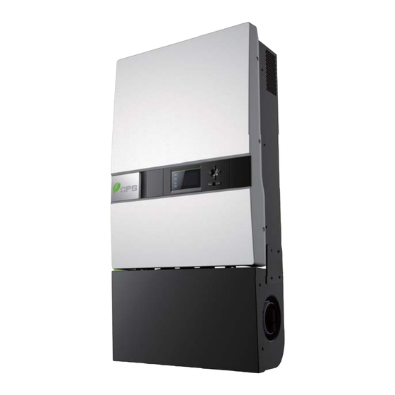
Filter PV2- Surge Protector Figure 2-2 Schematic diagram of CPS SC20KTL-DO/US-480 2.5 Appearance description Figure 2-3 Appearance sketch of CPS SC20KTL-DO/US-480 Description of main items of the inverter (shown in Figure 2-3): 1. LCD key buttons: operate the functions and change settings of inverter 2. -
Page 10: Chapter 3 Installation
Before installation, please check that the following items are included in the package: Table 3-1 Main items Q’ty Item Note (1) CPS SC20KTL-DO/US-480 Grid-tied PV inverter Grid-tied PV inverter upon which Inverter is hung (2) Mounting bracket and mounted onto a wall... -
Page 11: Basic Requirements
output wires, 1 for neutral wire (optional) RJ45 connecters for communication cables for inverter with 1 MPPT Red wire working alone 3.1 Basic requirements Check that the product environmental specifications (protection degree, operating temperature range, humidity and altitude, etc) meet the requirements of the specific project location;... -
Page 12: Mechanical Installation
3.2 Mechanical installation (1) Dimensions Figure 3-1 Dimensions of CPS SC20KTL-DO/US-480 (2) Installation method (see Figure 3-2): Make sure that the mounting structure (wall, rack, etc) is suitable to support the inverter weight. Follow the mounting guidelines below: (a) If the location permits, install the inverter vertically. - Page 13 Figure 3-2 Mounting the inverter properly (3) Space required for inverter mounting on the wall (as shown in Figure 3-3) The distances between the inverter and the surrounding objects should meet the following conditions: two sides from the walls ≥11.81 inches; top distance ≥11.81 inches;...
- Page 14 Figure 3-3 Inverter mounting dimensions (3) Secure the bracket with bolts through the mounting holes and install the inverter: (a) Mark the 6 bolt holes for mounting the bracket as shown in Figure 3-4;...
- Page 15 Figure 3-4 Bracket mounting dimensions (b) Drill holes at the marked positions with a diameter of 0.4 inch drill and put the 6 M8*25 expansion bolts into the holes; (c) Take the mounting bracket out of the package and secure the bracket on the wall with the 6 nuts in pair as shown in Figure 3-5;...
- Page 16 Figure 3-5 Positions of bolt holes on the bracket (d) Screw off the bolts and remove the two panels on both sides of the inverter as shown in Figure 3-6; Figure 3-6 Removal of panels before mounting inverter (e) Two people grab at the position on each side, lift up the inverter and then hang it on the bracket (Figure 3-7a~e).
- Page 17 Hand Grab Figure 3-7a Mounting inverter on the bracket Figure 3-7b Mounting inverter on the bracket...
- Page 18 Figure 3-7c Mounting inverter on the bracket Figure 3-7d Mounting inverter on the bracket...
- Page 19 Figure 3-7e Mounting inverter on the bracket (f) Put the two removed panels back and secure them with 4 M4*12 bolts on each side, as shown in Figure 3-8. Figure 3-8 Securing panels on both sides...
-
Page 20: Electrical Installation
3.3 Electrical installation INSTRUCTION: Conduits shall be used as the cable protectors for cable connection. The knockouts for cable entry of CPS SC20KTL-DO/US-480 are shown in Figure 3-9: DC input AC output and ground Signal port Figure 3-9 Knockouts for cable entry The 5 ports on the left are for DC input, AC output and ground connections, matching the 1¼... - Page 21 orientation, and tilt of PV modules may differ for different application. (2) Wire connection for DC input (a) Wire connection between PV modules and inverter: Table 3-3 Common configurations DC input 2 MPPTs working independently 1 MPPT working alone IN1+ PV1+ IN1+ PV1+...
- Page 22 PV1+ PV1+ IN1+ IN1+ PV1- IN1- PV1- IN1- 4 strings Inverter Inverter PV2+ PV2+ IN2+ IN2+ PV2- PV2- IN2- IN2- Table 3-4 Wiring requirement 4 strings 6 strings 7 strings 8 strings Positive 14~10AWG 16~10AWG 16~10AWG 18~10AWG Negative 14~10AWG 16~10AWG 16~10AWG 18~10AWG Bolts...
- Page 23 Table 3-6 Configurations for rare occasions 2 MPPTs working 1 MPPT working alone input independently PV1+ IN1+ PV1+ IN1+ IN1- IN1- PV1- PV1- Inverter Inverter PV2+ IN2+ PV2+ IN2+ strings PV2- IN2- PV2- IN2- PV1+ IN1+ IN1- PV1- 1 string Inverter IN2+ IN2-...
- Page 24 Figure 3-10 Wire stripping of DC input (c) Crimp the terminal as shown in Figure 3-11: Figure 3-11 Terminal crimping of DC input (d) The order of wire connection from left to right is PV1-, PV1+, PV2-, PV2+. Connect the PV1- and PV2- to the corresponding fuse socket of the negative pole and connect the PV1+ and PV2+ to the corresponding fuse socket of the positive pole with M5×12 bolts (4 PCS in total) as shown in Figure 3-12:...
-
Page 25: Ac And Ground Connection
(IN2+) wire socket (in the Wiring box) through the red wire in the accessory kit; Connect J2 (IN1-) with J4 (IN2-) wire socket through the black wire in the accessory kit, as shown in Figure 3-13: Figure 3-13 Wire connection in the Wiring box (1 MPPT working alone) 3.3.2 AC and ground connection The following describes how to connect the AC output and grounding cables between the inverter and the public power grid:... - Page 26 Torque 1.19N-M (10.5Lb-In.) value (2) Wire connection for AC output: (a) Insert the cables through steel conduits and strip the skin 0.4 inch off the cables as shown in Figure 3-14: Figure 3-14 Diagram for wire stripping of AC output (c) Crimp the terminal as shown in Figure 3-15: Figure 3-15 Diagram for terminal crimping of AC output (d) Connect the L1, L2, L3 and Neutral (red, black, blue, grey) AC output...
- Page 27 shown in Figure 3-17: Figure 3-17 Diagram for terminal crimping of grounding conductor (c) Connect the Gnd wire with a M5 nut at the marked place on the lower right side of the Wiring box, as shown in Figure 3-18: Figure 3-18 Diagram for wire connection of AC output and Grounding...
-
Page 28: Communication Connection
3.3.3 Communication connection There are two RS485 signal ports on the inverter. Shielded cables should be used for communication cables with the maximum length of 3280 feet. (1) The communication of one single local inverter is to connect the RS485 communication bus cable through the RS485-1 or RS485-2 port of the inverter directly. - Page 29 (3) RS485 network connection: When the inverters are monitored via the RS485 communication, the unique RS485 address for each inverter can be set through the LCD interface. Up to 31 inverters can be connected together in the RS485 communication network. The Daisy-chain topology is recommended for the RS485 network connection, as shown in Figure 3-20.
- Page 30 Figure 3-21 Diagram of communication wiring...
-
Page 31: Chapter 4 User Interface
Chapter 4 User Interface 4.1 Description of LCD panel The CPS SC20KTL-DO/US-480 LCD panel mainly consists of LCD screen, LED indicator lights, buzzer and 6 keys, as shown in Figure 4-1. Figure 4-1 LCD panel Interpretation for the indicator lights is shown in Table 4-1 and function of the keys is shown in Table 4-2. - Page 32 Light In other operation status or power supply not working Light Grid is normal Grid status GRID Flash Grid fault (light up 0.5s, light off 1.6s) indication Light light Power supply not working Light Indicates a Fault Slow Indicates Alarm (light up 0.5s, light off Fault status flash...
-
Page 33: Operation State
Right +1 when setting parameters 4.2 Operation state Table 4-1 indicates the definitions of LED, i.e. indicates the information of the inverter’s operation state. It indicates that the system is energized and under DSP control when “POWER” lights up. “RUN” will light up when the inverter detects that the grid connection conditions meet the requirements and power is fed into the grid. - Page 34 Figure 4-2 LOGO interface (2) Indication of inverter operation mode: Sys.Checking >>>>>> Figure 4-3 Inverter system check ongoing Standby >>>>>> Figure 4-4 Inverter system in standby mode Figure 4-5 Default display interface for normal operation...
-
Page 35: Menu Functions
SPICommErr Figure 4-6 Fault indication interface LCD screen will display different mode interfaces based on the operation modes of the inverter. There are four operation modes: startup system check mode (as shown in Figure 4-3), stand-by mode (as shown in Figure 4-4), normal operation mode (as shown in Figure 4-5, the switching time between (a) and (b) is 5 seconds), and fault mode (as shown in Figure 4-6). -
Page 36: Operation Information
Figure 4-7 Main menus on the LCD screen The main operation interface of LCD screen has 5 menus, i.e. “1 OP. Info”, “2 Alarm”, “3 History”, “4 Setting” and ”5 Dispatch”. The users may select options with PAGEUP and PAGEDOWN, and then press ENT to confirm selection. -
Page 37: Alarm
Figure 4-8 Operation information indication 4.3.4 Alarm As described before, when faults occur during the normal operation of the inverter, corresponding fault message will be indicated in “2 Alarm” menu besides the sound and light alarms. Move the cursor to “2 Alarm” and press ENT to check out the specific fault information, as shown in Figure 4-9. -
Page 38: System Setup
(3) Software version, hardware version and serial number of the product are listed in “3 Version” menu. (4) Cumulative generated power since the first day the inverter began working is available to be found in “4 TotalTag” menu. If not existed No Alarm 1.St2010.12.15 20:50 SPICommErr... - Page 39 the bottom of LCD screen ; move the cursor to “OFF” and press ENT , then “OFF State” will be indicated as well. The inverter will stand by instead of working normally if the startup conditions are not satisfied even “ON” is selected.
-
Page 40: Power Dispatch
→ ON ON State 中文 → English 1 ON/OFF 2 Language 3 Buzzer 4 Setting →4 SysTime English Ver. 5 Commun. KeyBeep Enable AlarmBeep → Disabled ↓ 2009 / 12 / 15 21 :14 → Address BaudRate 3 1 2400 2 4800 3 9600 4 115200... -
Page 41: System Protection Parameters Setup
4-12: 5 Dispatch 1 OP. Info 2 Alarm 3 History →4 Setting Figure 4-12 Contents indicated on the main operation interface Press ENT to the interface shown in Figure 4-13. ActivePower(%) 100.0 PowerFactor 1.000 Figure 4-13 Parameters of power dispatch Remote dispatch method: The “ActivePower”... - Page 42 Table 4-3 Protection Parameters Table Setup range (lower LCD indication Description limit, default & upper limit) (200, 528, 533V) GridV.Max(V) Grid voltage upper limit GridVmaxTripT(S) Trip time under Max. Grid V. (0.05, 1.80, 2.00S) (0, 422, 480V) GridV.Min(V) Grid voltage lower limit (0.05,1.80,...
- Page 43 (2) “2 Restart” menu. If an internal fault shutdown happens, a severe fault has occurred inside the inverter. The user may perform a force restart once in this menu if the user needs to restart the inverter. INSTRUCTION: The “Restart” function is effective only when the fault “IntFaultA~O” in the troubleshooting table occurs.
- Page 44 GridV.Max(V) GridV.Min(V) GridF.Min(Hz) → 59.30 → 528 → 422 GridVmaxTripT (S) GridVminTripT (S) GridFTripT (S) 0.08 1.80 1.80 →1 SysPara. Pls Input Pwd **** 2 Restart Are You Sure? 3 Recover 4 ClrErrRecd Restarting... Initialization? PwdError Pls Input Again Success! Recovering..
-
Page 45: Chapter 5 Operation
Chapter 5 Operation 5.1 Start-up Manual start-up: Manual start-up is required after regulation setting or manual (fault) shut-down. Move the cursor from the main operation interface to “4 Setting”. Press ENT and go to submenu “1 ON/OFF”. Then move the cursor to “ON”... - Page 46 (2) Normal operation mode: Default indication interface for normal operation of CPS SC20KTL-DO/US-480 is shown in Figure 5-2 (a) and 5-2 (b). The switching time between (a) and (b) is 5 seconds.
-
Page 47: Grid Connection And Power Generation
Power Grid before maintaining and operating the equipment. 5.4 Grid connection and power generation CPS SC20KTL-DO/US-480 inverter has an automatic grid-tied power generation process. It will check constantly whether AC power grid meets the conditions for grid-tied power generation, and also test whether the PV array... -
Page 48: Fault Shutdown
has adequate energy. After all conditions are met, the inverter will enter grid-tied power generation mode. While in grid-tied power generation, the inverter can detect the power grid at all times, and also keep the photovoltaic array output in maximum power point tracking (MPPT) mode. In case of any abnormity, the inverter will enter the protection program immediately. - Page 49 Table 5-1 Troubleshooting Table Definition: Prompt detection of abnormal temperature Possible causes: 1. Temperature Sensor socket connecter has poor contact; 1. TempSensorErr 2. Temperature Sensor is damaged; Recommended solutions: 1. Observe temperature display; 2. Switch off 3-phase working power supply and then reboot the system;...
- Page 50 Definition: Fan (invisible from outside) inside inverter is working abnormally Possible causes: 1. Fan service life has expired; 2. Fan socket connecter has poor contact. 3. IntFanErr Recommended solutions: 1. Observe for 5 minutes and see whether the alarm will be eliminated automatically; 2.
- Page 51 Possible causes: Internal memory has a certain problem Recommended solutions: 1. Observe for 5 minutes and see whether the alarm will be eliminated automatically; 2. Contact after-sales service personnel Definition: Ambient temperature or temperature inside inverter is too high Possible causes: 1.
- Page 52 Possible causes: 1. Grid voltage is abnormal; Power grid breaks down 2. Cable connection between the inverter and the grid is poor; Recommended solutions: 1. Observe for 10 minutes and see whether the alarm will be eliminated automatically; 2. Check whether the grid voltage is within the specified range;...
- Page 53 abnormalities; 4. Contact after-sales service personnel Definition: PV voltage exceeds the specified value Possible causes: PV over-voltage Recommended solutions: PV1(2) 1. Observe for 30 minutes and see whether the VoltOver* alarm will be eliminated automatically; 2. Check whether PV voltage exceeds the specified range;...
- Page 54 2. Grounding is abnormal; 3. Fault inside the inverter Recommended solutions: 1. Observe for 10 minutes and see whether the alarm will be eliminated automatically; 2.. Detect whether the electrical connection is abnormal 3. Contact after-sales service personnel Definition: Insulation impedance of PV positive to ground or PV negative to ground exceeds the specified range Possible causes:...
- Page 55 Internal fault of the inverter Possible causes: Fault occurs inside the inverter Recommended solutions: 1. The inverter can be forced to restart once if it is required by operation and if it is confirmed that there is no other problem; 2.
-
Page 56: Chapter 6 Service And Maintenance
Chapter 6 Service and Maintenance The CPS SC20KTL-DO/US-480 inverter is usually maintenance-free. CAUTION: Although designed to meet international safety standards, the PV-Inverter can become hot during operation. Do not touch the heat sink or peripheral surfaces during or shortly after operation. - Page 57 wire connectors as shown in Figure 6-2; Figure 6-2 Unplugging the wire connectors (3) Remove the 4PCS screws off the fan bracket as shown in Figure 6-3 and 6-4; (Tool: 0.12 inch Hexagon socket screw key) Figure 6-3 Unscrew the fan bracket on the left side Figure 6-4 Unscrew the fan bracket on the right side (4) Pull out the fan tray assembly from the left side of inverter as shown in Figure 6-5;...
-
Page 58: Restoring Of Fan Tray Assembly
Figure 6-5 Pulling out the fan tray assembly (5) Use a dry cloth to clean the fan tray assembly to prevent dirt accumulating on it. Do not use abrasive cleaning agents to avoid the damage of fans. 6.2 Restoring of fan tray assembly (1) Insert the fan tray assembly from the left side of the inverter as shown in Figure 6-6;... - Page 59 bracket is well connected, as shown in Figure 6-8 and 6-9; Figure 6-8 Revealing the wire connectors Figure 6-9 Fan tray assembly well connected (4) Connect the fan tray assembly with the inverter by plugging the wire connectors as shown in Figure 6-10; Figure 6-10 Plugging the wire connectors (5) Fix the left side of fan bracket on the Main housing with 2PCS screws...
- Page 60 as shown in Figure 6-11; (Tool: 0.12 inch Hexagon socket screw key) Figure 6-11 Fixing the fan bracket on the left side (6) Fix the right side of fan bracket on the Main housing with 2PCS screws as shown in Figure 6-12; (Tool: 0.12 inch Hexagon socket screw key) Figure 6-12 Fixing the fan bracket on the right side (7) Put the two removed panels back and secure the M4 screws on both...
- Page 61 Figure 6-13 Securing panels on both sides...
-
Page 62: Chapter 7 Technical Data
Chapter 7 Technical Data Model Name CPS SC20KTL-O/US-480 DC Input Max. PV Power 27kW Nominal DC Input Power 21kW Max. DC Input Voltage 600Vdc Operating DC Input 260-580Vdc Voltage Range Start-up DC Input Voltage / 300V / 200W Power Nominal DC Input Voltage... - Page 63 Output Frequency Range 59.3-60.5Hz Power Factor >0.99 Current THD <3% AC Disconnection Type Switch System Topology Transformerless Max. Efficiency 97.3% CEC Efficiency 96.5% Stand-by / Night <20W / <2W Consumption Environment Protection Degree NEMA 3R Cooling Variable speed cooling fans Operating Temperature -13°...
-
Page 64: Chapter 8 Limited Warranty
The warranty policy of this product is specified in the contract; otherwise, the warranty period is 5 years. For service, Chint Power Systems America will provide local support. For Warranty terms, please refer to the CPS America standard warranty policy in place at time of purchase. - Page 65 CHINT POWER SYSTEMS AMERICA CO., LTD. Address: 700 International Parkway Web: www.chintpower.com/na Suite 102 Email: americasales@chintpower.com Richardson TX 75081 Service Hotline: 855-584-7168 SHANGHAI CHINT POWER SYSTEMS CO., LTD. All rights reserved. Specifications and designs included in this manual are subject to change without notice. CHINT POWER 2013/09-MKT PN: 9.0020.0038G0...
Need help?
Do you have a question about the SC Series and is the answer not in the manual?
Questions and answers