
Related Manuals for CPS SC Series


Summary of Contents for CPS SC Series
- Page 1 CPS SC Series Grid-tied PV Inverter CPS SC14KTL-DO/US-208 CPS SC20KTL-DO/US-480 Installation and Operation Manual Version 1.4 CHINT POWER SYSTEMS AMERICA CO., LTD.
-
Page 3: Table Of Contents
Table of Contents Before You Start… ..................1 Chapter 1 IMPORTANT SAFETY INSTRUCTIONS ........2 Chapter 2 Overview .................. 5 2.1 Inverter for grid-tied PV systems ........... 5 2.2 Product type description ..............5 2.3 Product features ................5 2.4 Circuit structure design ..............6 2.5 Appearance description .............. -
Page 5: Before You Start
This manual contains important information regarding installation and safe operation of this unit. Be sure to read this manual carefully before using. Thanks for choosing this CPS Grid-tied PV Inverter. This PV Inverter is a high performance and highly reliable product specifically designed for the North American Solar market. -
Page 6: Chapter 1 Important Safety Instructions
Chapter 1 IMPORTANT SAFETY INSTRUCTIONS (SAVE THESE INSTRUCTIONS) Please read this user manual carefully before product installation. CPS reserves the right to refuse warranty claims for equipment damage if the user fails to install the equipment according to the instructions in this manual. - Page 7 Markings on the product HIGH VOLTAGE: The product works with high voltages. All work on the product must only be performed as described in this document. HOT SURFACE: The equipment is designed to meet international safety standards, but surfaces can become hot during operation. Do not touch the heat sink or peripheral surfaces during or shortly after operation.
- Page 8 CAUTION: CPS SC20KTL-DO/US-480 & SC14KTL-DO inverter is approx 63kg (≈132 pounds). Please ensure the mounting is properly installed before hanging the the inverter on the bracket. CAUTION: CPS SC20KTL-DO/US-480 & SC14KTL-DO series inverter have the Arc Fault Detection feature in the disabled mode by default. Please ensure that this setting meets local code requirements.
-
Page 9: Chapter 2 Overview
Chapter 2 Overview 2.1 Inverter for grid-tied PV systems CPS SC20KTL-DO/US-480 & SC14KTL-DO inverter is suitable for use with various commercial rooftop systems and distributed power station systems. Normally, the system mainly consists of PV modules, DC power distribution equipments, PV inverter and AC power distribution equipments (Figure 2-1). -
Page 10: Circuit Structure Design
Integrated AFCI (Arc Fault Circuit Interruption) feature enables the need to meet advanced local electrical and grid codes. This feature is disabled by default but can be enabled if needed in the field. Please contact CPS at HOTLINE: 855-584-7168 number to get instructions. -
Page 11: Appearance Description
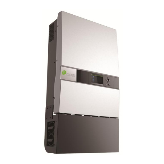
EMI filter to produce high quality AC power. DC_Switch AC_Switch Filter PV1+ DC/DC Filter Filter PV1- Lighting surge Lighting surge PV2+ DC/DC Filter PV2- Lighting surge Figure 2-2 Schematic diagram of CPS SC20KTL-DO/US-480 & SC14KTL-DO 2.5 Appearance description Figure 2-3 Appearance sketch of CPS SC20KTL-DO/US-480 & SC14KTL-DO/US-208... - Page 12 Description main items SC20KTL-DO/US-480 & SC14KTL-DO/US-208 (See Figure 2-3): 1. LCD key buttons: operate the functions and change settings of inverter 2. LCD display: indicates data 3. LED indicator lights: indicate the status of inverter 4. Holes for cable entry 5.
-
Page 13: Chapter 3 Installation
Below is the installation instruction of the inverter. Please read carefully and install the product step-by-step. 1. CPS SC20KTL-DO/US-480 & SC14KTL-DO/US-208 Check and make sure that the following items are included in the package before installation, as shown in Table 3-1. -
Page 14: Basic Requirements
16 for DC input cables, 4 Pre-insulated end ferrule for AC output cables RJ45 connecters for communication cables for grounding wire (1 nut for Flange M5 nut backup use) for inverter with 1 MPPT Red wire working alone for inverter with 1 MPPT Black wire working alone 3.1 Basic requirements... -
Page 15: Mechanical Installation
Do not install the inverter near the electromagnetic source which can compromise the normal operation of electronic equipment; 3.2 Mechanical installation (1) Dimensions The dimensions of CPS SC20KTL-DO/US-480 & SC14KTL-DO inverter are shown in Figure 3-1. 21.42in 8.46in 215mm 544mm Figure 3-1 Dimensions of CPS SC20KTL-DO/US-480 &... - Page 16 (2) Installation method Make sure that the mounting structure (wall, rack, etc) is suitable to support the inverter weight. Follow the mounting guidelines below: (a) If the location permits, install the inverter vertically. (b) If the inverter cannot be mounted vertically, it is allowed to be tilted backward by Max.
- Page 17 NOTICE: When the inverter is mounted backward by ≤15° outdoor, shield cover is required to be installed above the inverter to avoid direct sunlight. (3) Space required for inverter mounting on the wall (as shown in Figure 3-3) The distances between the inverter and the surrounding objects should meet the following conditions: two sides from the walls ≥11.81 inches;...
- Page 18 (3) Secure the bracket with bolts through the mounting holes and install the inverter: (a) Mark the 6 bolt holes for mounting the bracket as shown in Figure 3-4; Figure 3-4 Bracket mounting dimensions (b) Drill holes at the marked positions with a diameter of 0.4 inch drill...
- Page 19 and put the 6 M8*25 expansion bolts into the holes; (c) Take the mounting bracket out of the package and secure the bracket on the wall with the 6 nuts in pair as shown in Figure 3-5; Figure 3-5 Positions of bolt holes on the bracket (d) Screw off the bolts and remove the two panels on both sides of the inverter as shown in Figure 3-6;...
- Page 20 Figure 3-6 Removal of panels before mounting inverter (e) Two people grab at the position on each side, lift up the inverter and then hang it on the bracket (Figure 3-7a~e). Make sure the inverter is securely hooked on the bracket; Hand Grab...
- Page 21 Figure 3-7a Mounting inverter on the bracket Figure 3-7b Mounting inverter on the bracket Figure 3-7c Mounting inverter on the bracket...
- Page 22 Figure 3-7d Mounting inverter on the bracket Figure 3-7e Mounting inverter on the bracket (f) Put the two removed panels back and secure them with 4 M4*12...
-
Page 23: Electrical Installation
Figure 3-8. Figure 3-8 Securing panels on both sides 3.3 Electrical installation INSTRUCTION: Metal conduits shall be used as the cable protectors for wire connection. Inverter cable terminals of CPS SC20KTL-DO/US-480 & SC14KTL-DO are shown in Figure 3-9:... -
Page 24: Dc Connection
① ② ③ Figure 3-9 Inverter cable terminals ① Knockout holes for 1 & 1.25inch conduit of DC inputs ② knockout hole for 1 & 1.25inch conduit of AC output and ground cables ③ Knockout hole for 0.5 & 0.75inch conduit of communication cables 3.3.1 DC connection (1) To ensure the optimal performance of the inverter, please read the following guidelines before DC connection:... - Page 25 Rare 2 strings Configuration IN1+ PV1+ 2MPPT- IN1- PV1- Independent Inverter Mode IN2+ PV2+ Bypass Fuse IN2- PV2- IN1+ PV1+ 1MPPT- IN1- PV1- Parallel Inverter Mode IN2+ PV2+ Bypass Fuse IN2- PV2- Current DC cable 10~6AWG Fuse Common 4 strings Configuration PV1+ IN1+...
- Page 26 PV1+ IN1+ 1MPPT- PV1- IN1- Parallel Inverter PV2+ IN2+ Mode PV2- IN2- Current DC cable 16~10AWG Common 5 strings Configuration PV1+ IN1+ 2MPPT- IN1- PV1- Independent Inverter PV2+ IN2+ Mode PV2- IN2- PV1+ IN1+ 1MPPT- PV1- IN1- Parallel Inverter IN2+ PV2+ Mode IN2-...
- Page 27 PV1+ IN1+ 2MPPT- IN1- PV1- Independent Inverter IN2+ PV2+ Mode PV2- IN2- IN1+ PV1+ 1MPPT- IN1- PV1- Parallel Inverter PV2+ IN2+ Mode PV2- IN2- Current 8.7A DC cable 18~10AWG Common 7 strings Configuration PV1+ IN1+ 2MPPT- IN1- PV1- Independent Inverter IN2+ PV2+ Mode...
- Page 28 IN1+ PV1+ 1MPPT- IN1- PV1- Parallel Inverter IN2+ PV2+ Mode PV2- IN2- Current 7.4A DC cable 18~10AWG Common 8 strings Configuration IN1+ PV1+ 2MPPT- IN1- PV1- Independent Inverter IN2+ PV2+ Mode IN2- PV2- IN1+ PV1+ 1MPPT- IN1- PV1- Parallel Inverter IN2+ PV2+ Mode...
- Page 29 Note 2: The recommended fuse types are configured according to the condition that the input strings are the same. (d) CPS SC20KTL-DO/US-480 & SC14KTL-DO inverter is equipped with standard 15A DC fuses. Customers must verify that the appropriate fuses are used depending on the actual configuration of PV strings.
- Page 30 Littelfuse KLKD fuse series are recommended. The detailed information is available customers find download from http://www.littelfuse.com/. (b) Insert the cables through steel conduits and strip the skin 0.4 inch off the cables as shown in Figure 3-10: Figure 3-10 Wire stripping of DC input (c) Crimp the terminal as shown in Figure 3-11: Figure 3-11 Terminal crimping of DC input (d) The order of wire connection from left to right is PV1+, PV1-, PV2+,...
- Page 31 Figure 3-12 Wire connection of DC input (e) The standard configuration is “Parallel mode” with 1MPPT working alone. If it needs to switch to the “Independent mode” with 2MPPTs working independently, please remove the red wire and black wire in the wiring box. (As shown in Figure 3.13) For the inverter with 2 MPPT working independently, disconnect J1 (IN1+) with J3 (IN2+) wire socket (in the Wiring box) through the red;...
-
Page 32: Ac And Ground Connection
Figure 3-13 Wire connection in the Wiring box (1 MPPT working alone) 3.3.2 AC and ground connection The following describes how to connect the AC output and grounding cables between the inverter and the public power grid: (1) Use the recommended cables: L1 (Line 1), L2 (Line 2), L3 (Line 3), Neutral and Gnd (Equipment grounding conductor):8~10AWG copper cored soft cables Table 3-8 Wiring requirement... - Page 33 Figure 3-14 Diagram for wire stripping of AC output (c) Crimp the terminal as shown in Figure 3-15: Figure 3-15 Diagram for terminal crimping of AC output (d) Connect the L1, L2, L3 and Neutral (red, black, blue, grey) AC output wires to the corresponding terminals on the PCB board.
- Page 34 Figure 3-17 Diagram for terminal crimping of grounding conductor (c) Connect the Gnd cable with a M5 nut at the marked place on the lower right side of the Wiring box, as shown in Figure 3-18(a). The Gnd cable can also be connected to the copper stick as shown in Figure 3-18(b).
-
Page 35: Communication Connection
Table 3-8 Specification of AC breaker selection Inverter AC breaker rated current(A) CPS SCA14KTL-DO/US-208 CPS SC20KTL-DO/US-480 3.3.3 Communication connection There are two RS485 signal ports on the inverter. Shielded cables should be used for communication cables with the maximum length of 3280 feet. - Page 36 White brown Brown N.C. (2) The wires are labeled 1~8 from left to right, as shown in Figure 3-19: Figure 3-19 Diagram of RS485-1/2 wiring (3) RS485 network connection: When the inverters are monitored via the RS485 communication, the unique RS485 address for each inverter can be set through the LCD interface.
- Page 37 Datalogger Figure 3-20 RS485 connection between inverters and datalogger (4) A terminal resistance of 120 ohms connected between Pin 1 and Pin 3 of RS485-1/2 of the first inverter in the multiple inverters string and data logger as shown in Figure 3-20 is recommended. (5) The connection inside the Wiring box of the inverter after the first one is shown in Figure 3-21: Figure 3-21 Diagram of communication wiring...
-
Page 38: Chapter 4 Operation
Chapter 4 Operation 4.1 Start-up and shut-down 4.1.1 Start-up Manual start-up: Manual start-up is required after initial installation or manual (fault) shut-down. Move the cursor from the main operation interface to “4 Setting”. Press ENTER and go to the password input area, enter “↑”... - Page 39 (2) Normal operation mode: Default indication interface for normal operation of CPS SC20KTL-DO/US-480 & SC14KTL-DO is shown in Figure 4-2 (a) and 4-2 (b). The switching time between (a) and (b) is 5 seconds.
-
Page 40: Grid Connection And Power Generation
Standby >>>>>> Figure 4-3 Inverter system in standby mode (4) Fault mode, as shown in Figure 4-4: The inverter will disconnect from the power grid and turn into fault mode when the inverter or power grid fails. Check the specific cause through “Troubleshooting table”... -
Page 41: Fault Shutdown
conditions. At the same time, it will also check whether the DC input of PV modules is sufficient. The inverter will turn into normal operation mode when both of AC and DC conditions are fulfilled. The inverter will disconnect from the power grid and switch to standby mode when the sunlight is weak and power generation is small. - Page 42 Table 4-1 Troubleshooting Table Definition: Prompt detection of abnormal temperature Possible causes: 1. Temperature Sensor socket connecter has poor contact; 1. TempSensorErr 2. Temperature Sensor is damaged; Recommended solutions: 1. Observe temperature display; 2. Switch off 3-phase working power supply and then reboot the system;...
- Page 43 Definition: Fan (invisible from outside) inside inverter is working abnormally Possible causes: 1. Fan service life has expired; 2. Fan socket connecter has poor contact. 3. IntFanErr Recommended solutions: 1. Observe for 5 minutes and see whether the alarm will be eliminated automatically; 2.
- Page 44 Possible causes: Internal memory has a certain problem Recommended solutions: 1. Observe for 5 minutes and see whether the alarm will be eliminated automatically; 2. Contact after-sales service personnel Definition: Ambient temperature or temperature inside inverter is too high Possible causes: 1.
- Page 45 Grid voltage exceeds the specified range, Possible causes: 1. Grid voltage is abnormal; Power grid breaks down 2. Cable connection between the inverter and the grid is poor; Recommended solutions: 1. Observe for 10 minutes and see whether the alarm will be eliminated automatically; 2.
- Page 46 inverter and power grid is disconnected or has abnormalities; 4. Contact after-sales service personnel Definition: PV voltage exceeds the specified value Possible causes: PV over-voltage Recommended solutions: 1. Observe for 30 minutes and see whether the 4.PV1(2)VoltOver* alarm will be eliminated automatically; 2.
- Page 47 module due to environmental factor; 2. Grounding is abnormal; 3. Fault inside the inverter Recommended solutions: 1. Observe for 10 minutes and see whether the alarm will be eliminated automatically; 2.. Detect whether the electrical connection is abnormal 3. Contact after-sales service personnel Definition: Insulation impedance of PV positive to ground or PV negative to ground exceeds the specified...
- Page 48 Definition: The electric arc occurs in the circuit. Possible causes: 1. The electric arc occurs on the DC side; 2. Fault with the ARC board Recommended solutions: 9. ARC Protect 1. Check whether the circuit is in good condition, including the cable aging and animal gnawing;...
- Page 49 Possible causes: Fault occurs inside the inverter Recommended solutions: 1. The inverter can be forced to restart once if it is required by operation and if it is confirmed that there is no other problem; 2. Contact after-sales service personnel INSTRUCTION: *The actual...
-
Page 50: Chapter 5 User Interface
Chapter 5 User Interface 5.1 Description of LCD panel The CPS SC20KTL-DO/US-480 & SC14KTL-DO LCD panel mainly consists of LCD screen, LED indicator lights, buzzer and 6 keys, as shown in Figure 5-1. Figure 5-1 LCD panel Interpretation for the indicator lights is shown in Table 5-1 and function of the keys is shown in Table 5-2. - Page 51 indication Derated running status (light up 0.5s, Flash light light off 1.6s) Light In other operation status or power supply not working Light Grid is normal Grid status GRID Flash Grid fault (light up 0.5s, light off 1.6s) indication Light light Power supply not working Light...
-
Page 52: Operation State
Down Page down in selection menu Left -1 when setting parameters Right +1 when setting parameters 5.2 Operation state Table 5-1 indicates the definitions of LED, i.e. indicates the information of the inverter’s operation state. It indicates that the system is energized and under DSP control when “POWER”... - Page 53 energized, as shown in Figure 5-2. Figure 5-2 LOGO interface (2) Indication of inverter operation mode: Sys.Checking >>>>>> Figure 5-3 Inverter system check ongoing Standby >>>>>> Figure 5-4 Inverter system in standby mode...
-
Page 54: Main Operation Interface
Figure 5-5 Default display interface for normal operation SPICommErr Figure 5-6 Fault indication interface LCD screen will display different mode interfaces based on the operation modes of the inverter. There are four operation modes: startup system check mode (as shown in Figure 5-3), stand-by mode (as shown in Figure 5-4), normal operation mode (as shown in Figure 5-5, the switching time between (a) and (b) is 5 seconds), and fault mode (as shown in Figure 5-6). -
Page 55: Operation Information
The main operation interface of LCD screen has 5 menus, i.e. “1 OP. Info”, “2 Alarm”, “3 History”, “4 Setting” and ”5 Dispatch”. The users may select options with PAGEUP and PAGEDOWN, and then press ENTER to confirm selection. Return to the previous menu by pressing ESC. 5.3.3 Operation information When the cursor moves to “1 OP. -
Page 56: Alarm
5.3.4 Alarm As described before, when faults occur during the normal operation of the inverter, corresponding fault message will be indicated in “2 Alarm” menu besides the sound and light alarms. Move the cursor to “2 Alarm” and press ENTER to check out the specific fault information, as shown in Figure 5-9. If not existed No Alarm 2 Alarm... -
Page 57: System Setup
are listed in “3 Version” menu. (4) Cumulative generated power since the first day the inverter began working is available to be found in “4 TotalTag” menu. If not existed No Alarm 1.St2010.12.15 20:50 SPICommErr If existed 2.Ed2010.12.15 20:59 IntProtectI …... - Page 58 Move the cursor to “ON” and press ENTER, “ON State” will then be indicated at the bottom of LCD screen ; move the cursor to “OFF” and press ENTER, then “OFF State” will be indicated as well. The inverter will stand by instead of working normally if the startup conditions are not satisfied even “ON”...
- Page 59 “ ARC Option ” is used to control the ON/OFF of the ARC function. “Enable” means to turn on this function while “Disable” means to turn it off by pressing “←”and“→”to select. Press ENTER to confirm. 2. “ARC Clear” is used to clear the ARC fault protection. When the “ARC Protect”...
-
Page 60: Power Dispatch
5.3.7 Power Dispatch (1) For CPS SC20KTL-DO/US-480 the following applies – “ActivePower” and “PowerFactor” parameters can be set up through LCD operations as well as remote control by software. Local dispatch order: Service personnel can adjust the “ActivePower” and “PowerFactor” parameters through LCD operations. For detailed setup steps, please refer to “5.3.8 System protection parameters setup”. - Page 61 (2) For CPS SC14KTL-DO/US-208 the following applies – Move the cursor to “5 Power/PF” in the main interface. Press ENT to access and check the parameters of “ActivePower” and “PowerFactor”, as shown in Figure 5-14. The user can set the parameters of the two options through LCD operations as well as remote control by monitoring software.
- Page 62 The “ReactiveMode” menu has 6 submenus (Figure 5-16), including “1 None”, “2 Dispatch”, “3 Q Set”, “4 PF Set”, “5 PF(P) Set” and “6 Q(U) Set”. 1 None 2 Dispatch 3 Q Set 4 PF Set Figure 5-16 Submenus of ReactiveMode 1.
-
Page 63: System Protection Parameters Setup
Figure 5-18. (1) Set up the system protection parameters in “1 SysPara” menu. The specification of protection parameters is shown in Table 5-3. Table 5-3(a) Protection Parameters Table for CPS SC20KTL-DO/US-480 Setup range (lower limit, default Description of parameter &... - Page 64 Table 5-3(b) Protection Parameters Table for CPS SC14KTL-DO/US-208 Setup range (lower limit, LCD indication Description default & upper limit) V.MaxI (V) Class I Max. grid voltage {224.0, 228.8, 249.0} VmaxTripTI (S) Class I Max. trip time {0.08, 1.00, 600.00} V.MinI (V) Class I Min.
- Page 65 V.RecoverT (S) Grid voltage recover time {0.08, 300, 600.00} Max. grid frequency F.MaxRecover {50.00, 60.4, 62.00} recover value Min. grid frequency F.MinRecover {58.00, 59.4, 60.00} recover value Grid frequency recover F.RecoverT {0.08, 300, 600.00} time PVStartVol (V) PV startup voltage {150.0, 295, 310.0} SoftStep (KW/S) Soft step...
- Page 66 (3) “3 Recover” menu, the manufacturer’s parameter default value can be restored when the inverter is not in operation mode. Otherwise, a “FaultOperated” will be prompted. (4) In “4 ClrErrRecd” menu, history information of the faults can be cleared. A confirmation is required to clear the records. GridF.Min(Hz) GridV.Max(V)...
-
Page 67: Chapter 6 Service And Maintenance
Although designed to meet international safety standards, the PV-Inverter can become hot during operation. Do not touch the heat sink or peripheral surfaces during or shortly after operation. The CPS SC20KTL-DO/US-480 & SC14KTL-DO inverter is usually maintenance-free. The following regular maintenance steps must nevertheless be carried out at regular intervals to ensure the inverter’s operation with optimal... - Page 68 Figure 6-1 Removal of panels on both sides (2) Disconnect the fan tray assembly from the inverter by unplugging the wire connectors as shown in Figure 6-2; Figure 6-2 Unplugging the wire connectors (3) Remove the 4PCS screws off the fan bracket as shown in Figure 6-3 and 6-4;...
-
Page 69: Restoring Of Fan Tray Assembly
in Figure 6-5; Figure 6-5 Pulling out the fan tray assembly (5) Use a dry cloth to clean the fan tray assembly to prevent dirt accumulating on it. Do not use abrasive cleaning agents to avoid the damage of fans. 6.2 Restoring of fan tray assembly (1) Insert the fan tray assembly from the left side of the inverter as shown in Figure 6-6;... - Page 70 Figure 6-7 Hooking the fan tray assembly (3) Make sure the wire connectors reveal from the right hole and the bracket is well connected, as shown in Figure 6-8 and 6-9; Figure 6-8 Revealing the wire connectors Figure 6-9 Fan tray assembly well connected (4) Connect the fan tray assembly with the inverter by plugging the wire connectors as shown in Figure 6-10;...
- Page 71 Figure 6-10 Plugging the wire connectors (5) Fix the left side of fan bracket on the Main housing with 2PCS screws as shown in Figure 6-11; (Tool: 0.12 inch Hexagon socket screw key) Figure 6-11 Fixing the fan bracket on the left side (6) Fix the right side of fan bracket on the Main housing with 2PCS screws as shown in Figure 6-12;...
- Page 72 Figure 6-13 Securing panels on both sides...
-
Page 73: Chapter 7 Technical Data
Chapter 7 Technical Data Model Name SC20KTL-DO/US-480 SC14KTL-DO/US-208 DC Input Max. PV Power 19kW (9.5kW/MPPT) 27kW (13.5kW/MPPT) Nominal DC Input Power 14.6kW 21kW Max. DC Input Voltage 600Vdc Operating DC Input Voltage 260-580Vdc 180-580Vdc Range Start-up DC Input Voltage / 300V / 100W Power Nominal DC Input Voltage... - Page 74 3Φ / N / PE (Optional 3Φ / N / PE Grid Connection Type Neutral Connection) Max AC Output Current Rated Output Frequency 60Hz Output Frequency Range 59.3-60.5Hz Power Factor >0.99 (Adjustable +/- 0.9) Current THD <3% AC Disconnection Type Switch System Topology...
- Page 75 300V. (See Figure 6-1) Po/Pn (300V,21kW) (550,18.2kW) 100% (260,18.2kW) 260 300 PV Voltage (V) Figure 6-1(a) DC voltage de-rating curve for CPS SC20KTL-DO/US-480 Po/Pn 100% 60 120 180 240 300 PV Voltage (V) Figure 6-1(b) DC voltage de-rating curve for CPS SC14KTL-DO/US-208...
- Page 76 122℉ 140℉ Tamb (50℃) (60℃) Figure 6-2 Environmental temperature de-rating curve Note : When the altitude is higher than 6562ft (2000m), the power of CPS SC20KTL-DO/US-480 & SC14KTL-DO/US-208 inverter needs derating.(see Figure 6-3) Figure 6-3 Derating curve with high altitude...
-
Page 77: Chapter 8 Limited Warranty
The warranty policy of this product is specified in the contract; otherwise, the warranty period is 5 years. For service, Chint Power Systems America will provide local support. For Warranty terms, please refer to the CPS America standard warranty policy in place at time of purchase. - Page 78 Tele: +86 -21 -3779 1222 -6300 Fax: +86 -21 -3779 1222 -6001 Website: www.chintpowersystems.com CPS SC20KTL-DO/US-480 & SC14KTL-DO Installation and Operation Manual This manual is subject to change without prior notification. Copyright is reserved. Duplication of any part of this issue is prohibited without written...
Need help?
Do you have a question about the SC Series and is the answer not in the manual?
Questions and answers