
Related Manuals for Baxi Main Combi Eco


Summary of Contents for Baxi Main Combi Eco
- Page 1 Combi Eco Installation & Service Instructions Range These instructions include the Benchmark Commissioning Checklist and should be left with the user for safe keeping. © Baxi Heating UK Ltd 2011...
- Page 2 Therefore the checklist only applies if the appliance is being installed in a dwelling or some related structure. © Baxi Heating UK Ltd 2011 All rights reserved. No part of this publication may The flowchart opposite gives guidance for installers on the...
-
Page 3: Installer Notification Guidelines
Benchmark Checklist ‘Gas Safe Register’ will issue a LABC will record the data Building Regulations Compliance and will issue a Certificate to the property owner certificate of compliance and inform the relevant LABC © Baxi Heating UK Ltd 2011... - Page 4 BS EN 14336 Installation & commissioning of water based heating systems. BS 7074 Expansion vessels and ancillary equipment for sealed water systems. BS 7593 Treatment of water in domestic hot water central heating systems. © Baxi Heating UK Ltd 2011...
- Page 5 If at any time when installing the boiler you feel that you may have injured yourself STOP !! DO NOT ‘work through’ the pain - you may cause further injury. IF IN ANY DOUBT DO NOT HANDLE OR LIFT THE BOILER - OBTAIN ADVICE OR ASSISTANCE BEFORE PROCEEDING !! © Baxi Heating UK Ltd 2011...
-
Page 6: Table Of Contents
System Details Site Requirements Flue Options Plume Displacement 10.0 Installation 11.0 Commissioning 12.0 Completion 13.0 Servicing 14.0 Changing Components 15.0 Setting the Gas Valve 16.0 Electrical 17.0 Short Parts List 18.0 Fault Finding Benchmark Checklist © Baxi Heating UK Ltd 2011... -
Page 7: Introduction
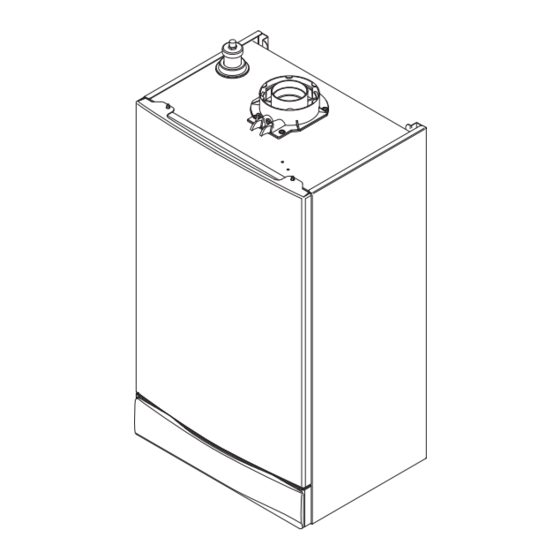
1.0 Introduction Description 1. The Main Combi Eco is a fully automatic gas fired wall mounted condensing combination boiler. It is room sealed and fan assisted, and will serve central heating and mains fed Case Front Panel domestic hot water. -
Page 8: General Layout
Central Heating Temperature Control Hot Water Temperature Control Water Pressure Sensor Gas/Air Inlet Burner Mounting Panel Igniter Burner On Light Central Heating Mode Light Domestic Hot Water Mode Light Display Position of Optional Integral Timer Reset © Baxi Heating UK Ltd 2011... -
Page 9: Appliance Operation
1. With the selector switch (see Section 2.1) in either the central heating or central heating and domestic hot water position, the pump will automatically operate for 1 minute in every 24 hours to prevent sticking. Fig. 3 © Baxi Heating UK Ltd 2011... -
Page 10: Technical Data
This value is used in the UK Government’s Standard Assessment Procedure (SAP) for energy rating of dwellings. The test data from which it has been calculated has been certified by 0087. 1000 1200 1400 © Baxi Heating UK Ltd 2011 Flow Rate (l/h) -
Page 11: Dimensions And Fixings
127 mm Condensate Drain 65 mm 65 mm 65 mm 65 mm 65 mm Heating Heating Domestic Hot Cold Water Pressure Relief Return Valve Flow Water Outlet Inlet Inlet (22mm) (22mm) (15mm) (22mm) (15mm) (15mm) © Baxi Heating UK Ltd 2011... -
Page 12: System Details
6.0 System Details Information 1. The Main Combi Eco Condensing Combination Boiler is a ‘Water Byelaws Scheme - Approved Product’. To comply with the Water Byelaws your attention is drawn to the following installation requirements and notes (IRN). a) IRN 001 - See text of entry for installation requirements and notes. - Page 13 3. The discharge must not be above a window, entrance or other public access. Consideration must be given to the possibility that boiling water/steam could discharge from the pipe. Fig. 6 Pressure Relief Valve Discharge Pipe © Baxi Heating UK Ltd 2011...
- Page 14 1. If the area of the installation is recognised as a HARD WATER AREA then a suitable device should be fitted to treat the mains water supply to the boiler. Contact your Water Distribution Company for advice on suitable devices. © Baxi Heating UK Ltd 2011...
-
Page 15: Site Requirements
Additional clearances may be required for the passage of pipes around local obstructions such as joists running parallel to the front face of the boiler. 450mm Min For Servicing Purposes 5mm Min In Operation Fig. 9 © Baxi Heating UK Ltd 2011... - Page 16 Zone 2 Building Regulations. In IE reference should be made to the current edition of I.S. Zone 0 813 “Domestic Gas Installations” and the current ETCI rules. 0.6 m Fig. 12 In GB Only © Baxi Heating UK Ltd 2011...
- Page 17 (e.g. sink waste) - Fig. 14 iii) to a drain or gully - Fig. 15 500mm min iv) to a purpose made soakaway - Fig. 16 Holes in the soak-away must face away from the building Fig. 16 © Baxi Heating UK Ltd 2011...
- Page 18 (see Top View Rear Flue Section 9.0). Fig. 17 Property Boundary Line Air Inlet Opening Window or Door 150mm Fig. 18a MIN. Likely flue positions requiring Fig. 18 a flue terminal guard © Baxi Heating UK Ltd 2011...
-
Page 19: Flue Options
NOTE: Horizontal flue pipes should always be installed with at least a 1.5° fall from the terminal to allow condensate to run back to the boiler. This bend is equivalent to 1 metre (ii) This bend is equivalent to 1 metre Total equivalent length = A+B+C+2x90°Bends © Baxi Heating UK Ltd 2011... - Page 20 This bend is equivalent to 1 metre Equivalent Length Air Duct = 6.5m FLUE DUCT Equivalent Sub total Length Value fittings/pipes 1m extension 5.0m 135°bend 0.5m 0.25m 91.5°bend 1.0m 0.5m Equivalent Length Flue Duct = 6.5m © Baxi Heating UK Ltd 2011...
- Page 21 91.5° 5118588 FLUE GROUP A, N, G Vertical Flue Kits Vertical Flue Terminal 5111078 (use with 5111070) Vertical Flue Terminal 5118576 Pitch Roof Flashing 25°/50° 5122151 Roof Cover Plate 246143 Flat Roof Flashing 246144 © Baxi Heating UK Ltd 2011...
- Page 22 (at least once every metre using the available pipe supports). Boiler Adaptor 3. Ensure that all joints and elbows are fully engaged and cannot become disconnected during operation. © Baxi Heating UK Ltd 2011...
- Page 23 Flue Deflector (Fig. 21) Fig. 20 1. If required, push the flue deflector over the teminal end and rotate to the optimum angle for deflecting plume. Secure the deflector to the terminal with screws provided. © Baxi Heating UK Ltd 2011...
-
Page 24: Plume Displacement
Installation & Servicing Instructions and BS5440 Pt. 1. It is NOT necessary to fit a terminal guard over the air inlet or the plume outlet. © Baxi Heating UK Ltd 2011... - Page 25 After consulting the table in Example 3 it can be determined Additional Accessories that the concentric flue could be up to approximately 2.3 93° Elbow 5121639 metres long. 45° Elbow (Pair) 5121370 Fig. 27 1 metre 60Ø Extension 5121638 © Baxi Heating UK Ltd 2011...
- Page 26 14. Fit the 93° elbow/plume outlet and secure with the two remaining screws supplied. Ensure the plume outlet is at least 45° to the wall and that the ‘peak’ is uppermost Fig. 33 (Fig. 33). © Baxi Heating UK Ltd 2011...
- Page 27 25. All other minimum & maximum dimensions must be adhered to, and the air inlet positioned such that it will not be subjetc to rain entry. Fig. 37 70° Concentric Flue Length (shown end-on) Outlet Spigot Fig. 38 © Baxi Heating UK Ltd 2011...
-
Page 28: Installation
1. Connect a tube to the central heating flow or return pipe (Fig. 41). For Side Flue Exit 2. Flush thoroughly (see System Details, Section 6.1). Fig. 40 Wall Plate Flushing Tube Fig. 41 Central Heating Return © Baxi Heating UK Ltd 2011... - Page 29 2. The connection will accept 21.5mm ( in) plastic overflow pipe which should generally discharge internally into the household drainage system. If this is not possible, discharge into an outside drain is acceptable. Fig. 44 Discharge Pipe © Baxi Heating UK Ltd 2011...
- Page 30 5. Mark dimension ‘Y’ on the flue as shown (Fig. 49). Adaptor Carefully cut the waste material from the flue, ensuring that the ducts are square and free from burrs. Fig. 47 Wall Thickness Fig. 48 Waste Flue Fig. 49 © Baxi Heating UK Ltd 2011...
- Page 31 Extension Fig. 53 Tape Cut End Adaptor Apply Lubricant for ease of assembly. Ensure Extension is fully engaged into Boiler Adaptor Fig. 54 © Baxi Heating UK Ltd 2011...
- Page 32 NOTE: The 230V switched signal for external controls (Frost Stat - Room Stat - Timer) must always be taken from terminal 2 at the boiler. Live, Neutral and Earth to power these controls must be taken from the Fused Spur. © Baxi Heating UK Ltd 2011...
-
Page 33: Commissioning
• The integrity of the flue system and the flue seals. • The integrity of the boiler combustion circuit and the relevant seals. Proceed to put the boiler into operation as follows: © Baxi Heating UK Ltd 2011... - Page 34 Conformity” to indicate compliance with I.S. 813. An example of this is given in I.S. 813 “Domestic Gas Installations”. This is in Fig. 65 addition to the Benchmark Commissioning Checklist. Fig. 67 Fig. 66 © Baxi Heating UK Ltd 2011...
-
Page 35: Completion
I.S. 813 “Domestic Gas Installations”. This is in addition to the Benchmark Commissioning Checklist. 5. Hand over the Users Operating, Installation and Servicing Instructions giving advice on the necessity of regular servicing. Facia Panel Fig. 68 © Baxi Heating UK Ltd 2011... -
Page 36: Servicing
(Fig. 70). 5. Unscrew the sump from the bottom of the condensate trap Sump assembly (Fig. 71) and remove any deposits from the sump and trap. Clean as necessary and replace the sump. Fig. 71 © Baxi Heating UK Ltd 2011... - Page 37 20. Complete the relevant Service Interval Record section of Blanking Cold Water Inlet Tap the Benchmark Commissioning Checklist at the rear of this publication and then hand it back to the user. Restricter Hydraulic Inlet Assembly Fig. 76 Filter © Baxi Heating UK Ltd 2011...
-
Page 38: Changing Components
2. Undo the extended nuts securing the electrode assembly to the combustion box panel and remove the assembly. 3. Check the condition of the sealing gasket and replace if necessary. Reassemble in reverse order. Sealing Gasket Spark Electrode Electrode Leads Fig. 78 © Baxi Heating UK Ltd 2011... - Page 39 Remove the pipe. 2. Extract and replace the injector and reassemble in reverse order. Check the condition of the sealing washers, replacing if necessary. Gasket Orifice Plate Air Box Gasket Fig. 81 © Baxi Heating UK Ltd 2011...
- Page 40 Electrode Assembly 5. Remove the electrode assembly and draw the insulation piece away. Replace the insulation and reassemble in Fig. 82 reverse order. Examine the heat exchanger gasket and replace as necessary. © Baxi Heating UK Ltd 2011...
- Page 41 3. Unscrew the sensor from the hydraulic outlet assembly. Examine the sealing washer,replacing if necessary. 4. Reassemble in reverse order. The plug will only fit one way. Pressure Sensor Plate Heat Exchanger Fig. 85 DHW Temperature Sensor © Baxi Heating UK Ltd 2011...
- Page 42 1. Drain the boiler primary circuit and unscrew the automatic air vent from the pump body. 2. Examine the ‘O’ ring seal, replacing if necessary, and fit it to the new automatic air vent. Fig. 89 3. Reassemble in reverse order. © Baxi Heating UK Ltd 2011...
- Page 43 4. Fit the new valve and ‘O’ ring seal and set to the previously noted orientation. Reassemble in reverse order. Fig. 92 ‘O’ ring seal Grub Screw Pressure Relief Valve Fig. 93 Discharge Pipe © Baxi Heating UK Ltd 2011...
- Page 44 Assembly 6. Remove the valve assembly. Examine any seals or washers, replacing if necessary. Transfer the DHW NTC to the new valve and reassemble in reverse order. Fig. 95 Pressure Sensor © Baxi Heating UK Ltd 2011...
- Page 45 4. Remove the screws securing the switch to the facia panel. Facia 5. Fit the new switch, ensuring that it is correctly positioned and reassemble in reverse order. Selector Switch Knob Temperature Control Knobs Fig. 98 © Baxi Heating UK Ltd 2011...
- Page 46 5. Locate the retaining bracket on the upper flange of the new vessel and fit to the boiler. 6. Examine the sealing washer, replacing if necessary, and reassemble in reverse order. Spring Washer Lock Nut Boiler Chassis Fig. 100 © Baxi Heating UK Ltd 2011...
-
Page 47: Setting The Gas Valve
DHW to settle before any further rechecked at minimum rate and knob. adjustment adjusted if required. 12. Check the Combustion Performance (CO/CO ratio). This must be less than 0.004. © Baxi Heating UK Ltd 2011... -
Page 48: Electrical
Optional Integral Timer Control PCB X501 Pump Spark Generator Diverter Valve Gas Valve Link Ignition Electrode Mains Input - green - brown - green / yellow - black - red - blue - grey - white © Baxi Heating UK Ltd 2011... -
Page 49: Short Parts List
Hall Effect Sensor 5114767 Burner 5130292 Water Pressure Switch 5114748 Plate Heat Exchanger 248048 Pump 248042 NTC Sensor DHW 5114725 Overheat Thermostat 5114729 NTC Sensor CH 5130291 Pressure Gauge 248090 PCB 25 5120217 PCB 30 5120218 © Baxi Heating UK Ltd 2011... -
Page 50: Fault Finding
5 seconds when E110 & E133 are displayed it is possible to relight the boiler. 4. If this does not have any effect, or the codes are displayed regularly further investigation is required. © Baxi Heating UK Ltd 2011... - Page 51 Burner output modulates to NTC sensor maintain the temperature set Go to section ‘E’ Pump continues to run for 3 Operation sequence Burner goes out Fan stops after 10 seconds minutes successful (room thermostat open) © Baxi Heating UK Ltd 2011...
- Page 52 Error 130 flashing Go to section ‘M’ Close DHW tap DHW flow sensor senses no Operation sequence Fan stops after 10 seconds Pump runs for 30 seconds flow. Burner goes out successful © Baxi Heating UK Ltd 2011...
- Page 53 Open the automatic air vent vent is opened Fan connections correct at fan. PCB - X2 connector, is 230V AC across Fan jammed or faulty winding Replace fan terminals 5 & 7 Replace PCB © Baxi Heating UK Ltd 2011...
- Page 54 110V AC across terminals 2 & 5 1. Ignition electrode and lead (Note: from multimeter connect 2. Electrode connection ‘common’ to 2 & ‘volys’ to 5) Replace igniter 3. Spark gap and position Check wiring © Baxi Heating UK Ltd 2011...
- Page 55 PCB - X401 connector terminals 5,6,7 & 8 Temperature sensors faulty. Cold resistance approximately Replace sensor @ 25° C (CH sensor) (resistance reduces with increase in temp.) Replace heat exchanger If pump is running the heat exchanger could be obstructed © Baxi Heating UK Ltd 2011...
- Page 56 19.0 Notes © Baxi Heating UK Ltd 2011...
- Page 57 19.0 Notes © Baxi Heating UK Ltd 2011...
-
Page 58: Benchmark Checklist
Failure to install and commission according to the manufacturer’s instructions and complete this Benchmark Commissioning Checklist will invalidate the warranty. This does not affect the customer’s statutory rights. If yes, and if required by the manufacturer, has a water scale reducer been fitted? CONDENSING BOILERS ONLY The condensate drain has been installed in accordance with the manufacturer’s instructions and/or BS5546/BS6798 If the condensate pipe terminates externally has the pipe diameter been increased and weatherproof insulation fitted? -
Page 59: Service Record
Service Record It is recommended that your heating system is serviced regularly and that the appropriate Service Interval Record is completed. Service Provider Before completing the appropriate Service Record below, please ensure you have carried out the service as described in the manufacturer’s instructions. -
Page 60: Description
A T r a d i n g D i v i s i o n o f B a x i H e a t i n g U K L t d ( 3 8 7 9 1 5 6 ) Brooks House, Coventry Road, Warwick. CV34 4LL After Sales Service 0844 871 1570 Technical Enquiries 0844 871 1555 Website www.mainheating.co.uk e&oe Comp N 5119466 - Iss 7 - 4/11 © Baxi Heating UK Ltd 2011...
Need help?
Do you have a question about the Main Combi Eco and is the answer not in the manual?
Questions and answers