Baxi Maxflow Combi WM Installation And Servicing Instructions
Gas fired wall mounted combination boiler
with unvented hot water storage
Hide thumbs
Also See for Maxflow Combi WM:
- Installation and servicing instructions (44 pages) ,
- User operating instructions manual (12 pages)

Related Manuals for Baxi Maxflow Combi WM


Summary of Contents for Baxi Maxflow Combi WM
-
Page 1: Installation And Servicing Instructions
Please leave these instructions with Baxi Maxflow Combi WM the user Gas fired Wall Mounted Combination Boiler with Unvented Hot Water storage Comp N 247308 - Iss 3 – 6/00 Installation and Servicing Instructions... - Page 2 Page 2 Baxi Maxflow Combi WM G.C. N 47 075 03 Baxi Limited is one of the leading manufacturers of domestic heating products in the UK. Our first priority is to give a high quality service to our customers. Quality is built into every...
-
Page 3: Table Of Contents
Contents - Page 3 Section Page Introduction General Layout Appliance Operation Technical Data Dimensions and Fixings System Details Site Requirements Installation Commissioning the Boiler 10.0 Servicing the Boiler 11.0 Changing Components 12.0 Illustrated Wiring Diagram 13.0 Fault Finding 14.0 Short Parts List... -
Page 4: Introduction
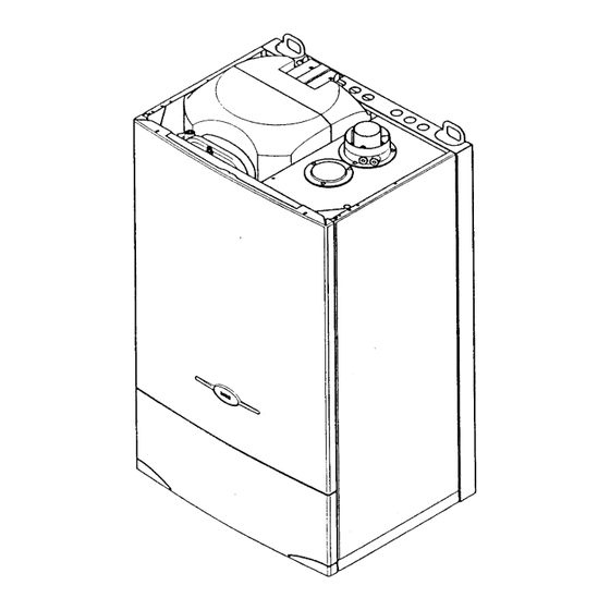
1.1 Description 1. The Baxi Maxflow Combi WM is a fully automatic gas fired wall mounted combination boiler incorporating a 54 litre unvented hot water storage cylinder. It is room sealed and fan assisted. -
Page 5: General Layout
General Layout – Page 5 2.1 Layout Fan Assembly Sensing Electrode Pressure Relief Valve Automatic Air Vent Circulation Pump Gas Valve Assembly Facia and Control Panel Optional Integral Timer Pressure Gauge Electrical Box Motorised Valve Burner Spark Electrodes Heat Exchanger Expansion Vessel Air Pressure Switch Cylinder Safety Valve... -
Page 6: Appliance Operation
Appliance Operation – Page 6 1.3 Boiler Operation 1. The boiler operating mode is controlled by the selector switch on the control panel. When set to it will operate in the Domestic Hot Water and Central Heating modes. For Domestic Hot Water only the selector switch should be set to 2. -
Page 7: Technical Data
Technical Data – Page 7... -
Page 8: Dimensions And Fixings
Dimensions and Fixings – Page 8... -
Page 9: System Details
System Details – Page 9 6.1 Information 1. The Baxi Maxflow Combi WM Combination Boiler is a ‘Water Byelaws Scheme - Approved Product’. To comply with the Water Byelaws your attention is drawn to the following installation requirements and notes (IRN). - Page 10 2. Suitable timer kits are available as optional extras. 3. For optimum operating conditions and maximum economy the fitting of a programmable thermostat, such as one of the Baxi Maxflow Combi WM Controllers, is recommended.
- Page 11 System Details – Page 11 6.5 System Filling and Pressurising 1. A filling point connection on the central heating return pipework must be provided to facilitate initial filling and pressurising and also any subsequent water loss replacement/refilling. 2. The filling method adopted must be in accordance with all relevant water supply bye-laws and use approved equipment.
- Page 12 System Details – Page 12 6.8 Domestic Hot Water Circuit 1. All DHW circuits, connections, fittings, etc. should be fully in accordance with relevant standards and water supply bye-laws. 2. Your attention is drawn to: IRN 116 and Byelaw 90 and 91. Sealed primary circuits and/or secondary hot water systems shall incorporate a means for accommodating the thermal expansion of water to prevent any discharge from...
-
Page 13: Site Requirements
Installation of gas fired hot water boilers. WARNING - The addition of anything that may interfere with the normal operation of the appliance without the express written permission of Baxi UK Limited could invalidate the appliance warranty and infringe the Gas Safety (Installation and Use) Regulations. - Page 14 Site Requirements – Page 14 7.4 Location 1. The boiler may be fitted to any suitable wall with the flue passing through an outside wall or roof and discharging to atmosphere in a position permitting satisfactory removal of combustion products and providing an adequate air supply.
- Page 15 7.8 Flue 1. An internal fitting kit is available for installations where the flue terminal is inaccessible from the outside. This is available direct from Baxi UK Limited. Quote Part N 236441 when ordering. 2. The following guidelines indicate the general requirements for siting balanced flue terminals.
- Page 16 Site Requirements – Page 16 7.9 Flue Dimensions The standard horizontal flue kit allows for flue lengths between 100mm and 1m from elbow to terminal (Fig. 17). The maximum permissible equivalent flue length is: 4 metres. NOTE: Each additional 45º of flue bend will account for an equivalent flue length of 0.5m.
- Page 17 Site Requirements – Page 17 7.12 Flue Options 1. The Baxi Maxflow Combi WM can be fitted with flue systems as illustrated. 2. The standard flue is suitable only for horizontal applications. 3. Maximum permissible equivalent flue lengths are: Horizontal 4.0 metres...
-
Page 18: Installation
Installation – Page 18 8.1 Initial Preparation & Fitting the Boiler The gas supply, gas type and pressure must be checked for suitability before connection (see Section 7.6). 1. Locate the wall template (Fig. 21) in the appliance packaging. 2. After considering the site requirements (see Section 7.0 ) position the template on the wall ensuring it is level both horizontally and vertically. - Page 19 Installation – Page 19 8.3 Fitting the Pressure Relief Discharge Pipe (Fig. 1. Remove the discharge pipe from the kit. 2. Determine the routing of the discharge pipe in the vicinity of the boiler. Make up as much of the pipework as is practical, including the discharge pipe supplied.
- Page 20 Installation – Page 20 8.5 Fitting The Flue HORIZONTAL FLUE 1. The standard flue is suitable for lengths 100mm minimum to 1m maximum (measured from the edge of the flue elbow outlet). Rear Flue: maximum wall thickness - 900mm Right Side Flue: maximum wall thickness - 875mm Left Side Flue: maximum wall thickness - 615mm 2.
- Page 21 21. Fit the circular flue trim outside if required, and if necessary fit a terminal guard (see Section 7.10 & 7.11). VERTICAL FLUE 1. Only a flue approved with the Baxi Maxflow Combi WM can be used. 2. For information on vertical flues consult the Baxi Maxflow Combi WM Installer Guide or Notes for Guidance supplied with the vertical flue pack.
- Page 22 Installation – Page 22 8.6 Making The Electrical Connections To connect the mains input cable proceed as follows:- 1. Hinge the facia panel downwards and undo the two screws retaining the control box to the boiler chassis. Allow the control box to hinge down (Fig. 33). 2.
-
Page 23: Commissioning The Boiler
Commissioning the Boiler – Page 23 9.1 Commissioning the Boiler 1. Reference should be made to BS 5449 Section 5 when commissioning the boiler. 2. Open the mains water supply to the boiler. 3. Open all hot water taps to purge the DHW system. 4. - Page 24 Commissioning the Boiler – Page 24 9.2 Checking the Burner Pressures (continued) 9. The burner will light and the pressure should increase to the maximum. Burner Pressures (mbar) Max. Min. 10.8 10. If the pressures are not as those shown in the table check that the inlet pressure is 20 mbar.
-
Page 25: Servicing The Boiler
10.0 Servicing the Boiler – Page 25 10.1 Annual Servicing 1 For reasons of safety and economy, it is recommended that the boiler is serviced annually. Servicing must be performed by a competent person. 2. After servicing, complete the relevant section of the “Benchmark”... - Page 26 10.0 Servicing the Boiler – Page 26 10.1 Annual Servicing (Continued) 16. Gently clean the heat exchanger with a soft brush, taking care not to damage any of the fins. 17. Inspect the side insulation pieces and replace if they are damaged or deteriorated in any way and brush out any debris or deposits from the combustion box.
-
Page 27: Changing Components
11.0 Changing Components – Page 27 IMPORTANT: When changing components ensure that both the gas and electrical supplies to the boiler are isolated before any work is started. See Section 10.0 “Annual Servicing” for removal of case panel, doors etc. 11.1 Pressure Switch (Fig. - Page 28 11.0 Changing Components – Page 28 11.4 Gas Valve (Fig. 54) 1. Undo the two screws securing the outercase bottom panel and remove the panel (Fig. 53). 2. Disconnect the wires from the valve coil and the pressure sensing tube from the valve. 3.
- Page 29 11.0 Changing Components – Page 29 11.5 Pressure Gauge (Figs. 55, 56 & 57) 1. Hinge the facia panel downwards and undo the two screws retaining the control box. Lower the control box. 2. Drain the primary circuit. 3. Undo the nut on the pressure gauge capillary from the manifold and remove the screws securing the gauge retaining bracket.
- Page 30 11.0 Changing Components – Page 30 11.7 Insulation (Figs. 60 & 61) There are four insulation pieces in the combustion box - two side pieces, one rear and one front attached to the combustion box inner panel. Side Pieces 1. Remove the screws securing the fan hood. Carefully draw the side insulation pieces out, easing the heat exchanger sideways while extracting each piece.
- Page 31 11.0 Changing Components – Page 31 11.10 Circuit Boards & Electrical Components (Figs. 65 & 66) See section 12.0 “Illustrated Wiring Diagram” for the layout of all electrical components. To gain access hinge the facia panel down and remove the screws securing the control box.
- Page 32 11.0 Changing Components – Page 32 11.11 Electrodes (Fig. 68) 1. Remove the burner as described in section 11 3 and undo the screw securing the relevant electrode to the burner assembly and remove. 2. Check the electrode positions and reassemble in reverse order.
- Page 33 11.0 Changing Components – Page 33 11.15 Diverter Valve- Head Only (Fig. 73) 1. Disconnect the three pin plug on the valve electrical input cable from the boiler wiring loom. 2. Slacken the screw securing the valve operating head cover. Pull the cover forwards to remove. 3.
- Page 34 11.0 Changing Components – Page 34 11.18 Expansion Vessel (Fig. 77) 1 Drain the primary circuit and undo the nut on the expansion pipe at the adaptor on the bottom of the vessel. 2. Undo the nut and washer securing the vessel to the mounting bracket on the side of the storage tank.
- Page 35 11.0 Changing Components – Page 35 11.20 Pump - Head Only (Figs. 82 & 83). 1. Drain the primary circuit and remove the socket head screws securing the pump head to the body and draw the head away. 2. Undo the screw on the pump wiring cover and remove the cover.
-
Page 36: Illustrated Wiring Diagram
12.0 Illustrated Wiring Diagram – Page 36 to 37 36-37... - Page 37 13.0 Fault Finding – Page 38...
-
Page 38: Fault Finding
13.0 Fault Finding – Page 39... - Page 39 13.0 Fault Finding – Page 40 Fault Finding Solutions...
- Page 40 13.0 Fault Finding – Page 41...
- Page 41 14.0 Short Parts List – Page 42 Short Parts List G.C. Description Manufacturers Part No. 393-947 Pressure Switch. 247380 378-864 247381 343-786 Burner 247387 E03-572 Pressure Differential Switch 247388 Pump Head 247390 379-796 Automatic Air vent 247391 Gas valve 247392 Diverter valve (3 Port Valve) 247395 385-839...
-
Page 42: Short Parts List
14.0 Short Parts List – Page 43 Short Parts List G.C. Description Manufactures Part No. Electrode Sensing 247382 Electrode Ignition Rear 247383 Electrode ignition Front 247384 Electrode Lead Ignition 247385 Electrode Lead Sensing 247386 Microswitch Loom 247389 Limit Thermostat (O/Heat) 247393 343-571 Temperature Sensor...
Need help?
Do you have a question about the Maxflow Combi WM and is the answer not in the manual?
Questions and answers