
Subscribe to Our Youtube Channel
Related Manuals for Baxi MAIN HEATING Main Eco Elite System 24


Summary of Contents for Baxi MAIN HEATING Main Eco Elite System 24
- Page 1 United Kingdom Installation & Service Manual Condensing Central Heating Boiler M M ain Eco Elite System 24 - 28 These instructions include the Benchmark Commissioning Checklist and should be left with the user for safe keeping.
-
Page 2: Natural Gas
Therefore the checklist only applies if the appliance is being installed in a dwelling or some related structure. © Baxi Heating UK Ltd 2017 All rights reserved. No part of this publication may The flowchart opposite gives guidance for installers on the... -
Page 3: Installer Notification Guidelines
Installer Notification Guidelines Choose Building Regulations Notification Route Competent Person's Building Control Self Certification Scheme Install and Commission this Contact your relevant Local appliance to manufacturer's Authority Building Control instructions (LABC) who will arrange an inspection or contact a government approved inspector Complete the Benchmark Checklist... - Page 4 Installation of gas fired hot water boilers. EC - Declaration of Conformity BS 5440 Part 1 Flues. Baxi Heating UK Limited being the manufacturer / distributor within the European BS 5440 Part 2 Ventilation. BS 7074 Expansion vessels and ancillary equipment for Economic Area of the following sealed water systems.
- Page 5 Safe Manual Handling General The following advice should be adhered to, from when first handling the boiler to the final stages of installation, and also during maintenance. Most injuries as a result of inappropriate handling and lifting are to the back, but all other parts of the body are vulnerable, particularly shoulders, arms and hands. Health &...
-
Page 6: Table Of Contents
CONTENTS Section Page Introduction General Layout Appliance Operation Technical Data Dimensions and Fixings System Details Site Requirements Flue Options Installation 10.0 Commissioning 11.0 Completion 12.0 Servicing 13.0 Changing Components 14.0 Setting the Gas Valve 15.0 Electrical 16.0 Short Parts List 17.0 Fault Finding Benchmark Checklist... -
Page 7: Introduction
1.0 Introduction Description Case Front Panel 1. The Main Eco Elite System is a fully automatic gas fired wall mounted condensing system boiler. It is room sealed and fan assisted. 2. The boiler is set to give a maximum output of :- 24 models - 25.94 kW 26.95 kW Pnc (Condensing) -
Page 8: General Layout
2.0 General Layout Layout Expansion Vessel Automatic Air Vent Primary Return Temperature Sensor Circulation Pump (NOTE: T he boiler can be fitted with one of two alternative pumps, Grundfos or Wilo. All boiler illustrations show Grundfos. Section 13.12 details both types). Drain Off Point Pressure Relief Valve Selector Switch... -
Page 9: Appliance Operation
3.0 Appliance Operation Boiler Primary Circuit Operating Mode (Fig. 2) 1. With a demand for heating or hot water, the pump circulates water through the primary circuit. If the pressure is at least 0.5 bar and the ignition sequence will start. 2. -
Page 10: Technical Data
4.0 Technical Data Main Eco Elite 24 & 28 System ErP Appliance Type NO x Class Inlet Pressure (Natural Gas - G20) mbar Appliance Category CAT I Central Heating Primary Circuit Pressures Injector (Natural Gas - G20) Heat Input CH Qn Hs (Gross) Safety Discharge 6.0mm (24 &... - Page 11 4.0 Technical Data Technical Parameters Technical parameters for boiler space heaters Main Eco Elite System ErP Condensing boiler Low-temperature boiler B1 boiler Cogeneration space heater Combination heater Prated Rated heat output Useful heat output at rated heat output 25.9 28.6 and high temperature regime Useful heat output at 30% of rated heat output and low temperature regime...
-
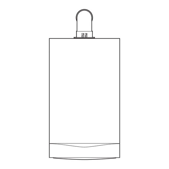
Page 12: Dimensions And Fixings
5.0 Dimensions and Fixings NOTE: There must be no part of the air duct (white tube) visible outside the property after installation. The flue seal should fit neatly and effect a good seal. For full detail refer to Section 9.6 “Fitting the Flue”. Dimensions A 780mm At Least 1.5... -
Page 13: System Details
6.0 System Details Central Heating Circuit 1. The appliance is suitable for fully pumped SEALED SYSTEMS ONLY. Treatment of Water Circulating Systems • All recirculatory water systems will be subject to corrosion unless an appropriate water treatment is applied. This means that the efficiency of the system will deteriorate as corrosion sludge accumulates within the system, risking damage to pump and valves, boiler noise and circulation problems. - Page 14 6.0 System Details System Filling and Pressurising (Fig. 6) 1. A filling point connection on the central heating return Double Stop Stop Check pipework must be provided to facilitate initial filling and Valve Valve Valve pressurising and also any subsequent water loss replacement/refilling.
-
Page 15: Site Requirements
7.0 Site Requirements 5mm Min 450mm 5mm Min Location 1. The boiler may be fitted to any suitable wall with the flue 175mm Min passing through an outside wall or roof and discharging to (300mm Min if using 80/125mm atmosphere in a position permitting satisfactory removal of flueing system) combustion products and providing an adequate air supply. -
Page 16: Site Requirement
7.0 Site Requirement Gas Service Cock Ventilation of Compartments 1. Where the appliance is installed in a cupboard or compartment, no air vents are required. 2. BS 5440: Part 2 refers to room sealed appliances installed in compartments. The appliance will run sufficiently cool without ventilation. -
Page 17: Condensate Drain
Examples are shown of the following methods of termination:- i) to an internal soil & vent pipe 7.0 Site Requirements ii) via an internal discharge branch (e.g. sink waste) downstream of the trap iii) to a drain or gully iv) to a purpose made soakaway Condensate Drain v) pumped into an internal discharge branch (e.g. - Page 18 v) pumped into an internal discharge branch 7.0 Site Requirement (e.g. sink waste) downstream of the trap Pipe must terminate above Sink Condensate Drain (cont.) water level but below surrounding surface. Cut end at 45° 12. A boiler discharge pump is available, ‘MULTIFIT’ part no.
- Page 19 Terminal Position with Minimum Distance (Fig. 14) (mm) 7.0 Site Requirements Directly below an opening, air brick, opening windows, etc. Above an opening, air brick, opening window etc. Horizontally to an opening, air brick, opening window etc. Flue (Figs. 13 & 14) Below gutters, soil pipes or drain pipes.
-
Page 20: Flue Options
8.0 Flue Options Horizontal Flue Systems 1. The standard flue is suitable only for horizontal termination applications. (ii) 2. All fittings should be fully engaged. The approximate engagement is 40mm. Apply the lubricant supplied to the seal on each fitting to aid assembly. 3. - Page 21 & chimney system is fitted safely and in compliance with the relevant standards and practices in force in the country of installation. Please leave these instructions with the Installation & Servicing Instructions. © Baxi Heating UK Ltd 2011 Fig. 16a...
-
Page 22: Installation
1.0 Introduction 9.0 Installation Unpacking & Initial Preparation The gas supply, gas type and pressure must be checked for suitability before connection (see Section 7.4). NOTE: a small amount of water may drain from the boiler in the upright position. 1. - Page 23 9.0 Installation Fitting The Boiler (Fig. 22) 1. Remove the sealing caps from the boiler connections. Remove Sealing Caps from NOTE: A small amount of water may drain from the boiler under the Boiler after lifting once the caps are removed. into position 2.
- Page 24 9.0 Installation Fitting The Flue HORIZONTAL TELESCOPIC FLUE 1. There are two telescopic sections, the Terminal Terminal Assembly Assembly and the Connection Assembly, a roll of sealing tape and two self tapping screws. A 93° elbow is also supplied. Connection Assembly 2.
- Page 25 Flue Elbow 9.0 Installation Fitting the Flue (Cont) Adaptor 10. Remove the flue elbow and insert the flue through the hole in the wall. 11. Refit the elbow to the boiler adaptor, ensuring that it is pushed fully in (Fig. 29). 12.
-
Page 26: Making The Electrical Connections
IMPORTANT 9.0 Installation • Any wiring to the boiler, from either the mains or an external control, MUST be cable of the following specification:- 0.75mm 3183/4/5Y (depending on installation) multi strand flexible cable Making The Electrical Connections conforming to BS 50525-2-11. •... -
Page 27: Commissioning
Heat Exchanger 10.0 Commissioning Automatic Air Vent Fig. 34 10.1 Commissioning the Boiler 1. Reference should be made to BS:EN 12828 & 14336 when commissioning the boiler. 2. At the time of commissioning, complete all relevant sections of the Benchmark Checklist at the rear of this publications. 3. - Page 28 Set Boiler to Maximum Rate 10.0 Commissioning (see 10.1.17) Allow the combustion to stabilise. Do not insert probe to 10.2 Checking Combustion avoid ‘flooding’ the analyser. 1. Follow the flow chart opposite. Perform Flue Integrity Combustion Check Insert the analyser probe into the air inlet test point, allowing the reading to stabilise.
- Page 29 10.0 Commissioning 10.3 Check the Operational (Working) Gas Inlet Pressure 1. Ensure that all controls are calling for heat, and the selector switch is in the central heating and hot water position ( Central Heating The current boiler temperature is shown on the display. Calibration Control Temperature Control Fig.
-
Page 30: Completion
11.0 Completion 11.1 Completion Case Front Panel 1. Instruct the user in the operation of the boiler and system including external controls, explaining the operational sequence. 2. Set the temperature control knob to the requirements of the user. 3. Carefully read and complete all sections of the Benchmark Commissioning Checklist at the rear of this publication that are relevant to the appliance and installation. -
Page 31: Servicing
12.0 Servicing 12 .1 Annual Servicing 1. For reasons of safety and economy, it is recommended that Case Front Panel the boiler is serviced annually. Servicing must be performed by a competent person in accordance with B.S. 7967-4. 2. After servicing, complete the relevant Service Interval Record section of the Benchmark Commissioning Checklist at the rear of this publication. - Page 32 12.0 Servicing 12.2 Annual Servicing - Inspection (Cont) Injector 6. Undo the nut on the gas pipe at the gas/air inlet (Fig. 49) Gas/Air Inlet and the gas valve. Remove the pipe, taking care not to lose the sealing washers. Also remove the injector. 7.
-
Page 33: Changing Components
13.0 Changing Components IMPORTANT: When changing components ensure that both the gas and electrical supplies to the boiler are isolated before any work is started. When the component has been changed turn the selector switch fully anticlockwise against the spring pressure to the Igniter reset position and hold for 5 seconds to reset the boiler before recommissioning. - Page 34 13.0 Changing Components Injector Gas/Air Inlet 13.3 1. Undo the nut on the gas pipe at the gas/air inlet (Fig. 54) and the gas valve. Remove the pipe, taking care not to lose the sealing washers. Also remove the injector. Gas Pipe 2.
- Page 35 13.0 Changing Components 13.5 Burner (Fig. 57) 1. Undo the nut on the gas pipe at the gas/air inlet and the gas valve. Remove the pipe, taking care not to lose the sealing washers. Also remove the injector. 2. Disconnect the electrode lead caps, remove the strain relief clip from the sensing lead and disconnect the lead.
-
Page 36: Dhw Temperature Sensor (Ntc)
13.0 Changing Components 13.7 Safety Thermostat (Fig. 58) 1. Pull the plug off the thermostat. 2. Remove the screws securing the thermostat to the mounting plate on the flow pipe. Safety Thermostat 3. Reassemble in reverse order, ensuring that the plug is pushed fully on. - Page 37 13.0 Changing Components Heat Exchanger Air Vent 13.11 Heat Exchanger Automatic Air Vent (Fig. 61 ) 1. Drain the boiler primary circuit and unscrew the automatic air vent from the pump body. 2. Examine the ‘O’ ring seal, replacing if necessary, and fit it to the new automatic air vent.
- Page 38 13.0 Changing Components 13.15 Pressure Gauge (Figs. 64 & 65) Gauge Retaining Bracket 1. Drain the boiler primary circuit and undo the nut on the pressure gauge capillary. 2. Undo the screws securing the gauge retaining bracket. 3. Remove the bracket and gauge assembly. Depress the barbs on the side of the gauge and remove the retaining bracket.
- Page 39 13.0 Changing Components 13.17 P.C.B. (Figs. 67 & 68) 1. Note the settings of the control knobs, rotate them fully anticlockwise and carefully pull them off the drive pins. 2. Completely undo the screws securing the control box cover and release the cover retaining barbs from their slots. 3.
- Page 40 4 full turns clockwise (Fig. 70). If the boiler will not light, or the correct CO cannot be achieved call Baxi Customer Support 0344 871 1545. Fig. 70 13.21 Expansion Vessel (Fig. 71) 1.
-
Page 41: Setting The Gas Valve
14.0 Setting the Gas Valve 14.1 Setting the Gas Valve ( check) IMPORTANT: The CO must be only be checked and adjusted to set the valve if a suitable calibrated combustion analyser is available, operated by a competent person - see Section 12.1 Central Heating Calibration Control Temperature Control... -
Page 42: Electrical
15.0 Electrical 15.1 Illustrated Wiring Diagram Central Heating NTC Sensor gr gr Return Heating Overheat Stat Temp Sensor Water Pressure Switch X400 X401 9 8 7 6 5 4 3 2 1 8 7 6 5 4 3 2 1 Pump (Grundfos) Control PCB... -
Page 43: Short Parts List
16.0 Short Parts List Short Parts List G.C. Description Manufacturers Part No. 5121447 Electrode Assembly 5130293 Gas Valve 720301001 Burner 5130292 Water Pressure Switch 5114748 Pump 7654033 NTC Sensor 5114725 Overheat Thermostat 5114729 NTC Sensor 5130291 Pressure Gauge 5118385 PCB 24 5131262 PCB 28 5131263... -
Page 44: Fault Finding
17.0 Fault Finding 18.1 Initial Fault Finding Checks NOTE: When instructed to turn the 1. Check that gas, water and electrical supplies are available selector to the reset position turn the at the boiler. selector switch fully anticlockwise against the spring pressure to the reset position 2. - Page 45 17.0 Fault Finding Refer to Section 16.0 “Illustrated Wiring Diagram” for position of terminals and components Central Heating - Follow operational sequence Turn selector switch to Go to section ‘A’ The display illuminates Error 110 flashing If the error 110 is still flashing. Turn the selector switch to Error 133 flashing reset position for 5 seconds...
- Page 46 17.0 Fault Finding Fault Finding Solutions Sections Is there 230V at: Main terminals L and N Check electrical supply Main terminal fuse Replace fuse Display Replace PCB illuminated Check wiring PCB - X1 connector terminals 1,2 Is there 230V at: X3 Connection Pump PCB Check incoming wiring X2 Connection Pump PCB...
- Page 47 17.0 Fault Finding Check and correct the connection of the tube between the venturi and gas valve Gas at burner Ensure gas is on and purged PCB - X3 connector is 230V AC across Replace gas valve terminals 1 & 2 Replace PCB voltage at PCB - X2 connector is Check and correct if necessary...
- Page 48 18.0 Notes...
- Page 49 18.0 Notes...
-
Page 50: Gas Boiler System Commissioning Checklist
GAS BOILER SYSTEM COMMISSIONING CHECKLIST This Commissioning Checklist is to be completed in full by the competent person who commissioned the boiler as a means of demonstrating compliance with the appropriate Building Regulations and then handed to the customer to keep for future reference. Failure to install and commission according to the manufacturer’s instructions and complete this Benchmark Commissioning Checklist will invalidate the warranty. - Page 51 SERVICE RECORD It is recommended that your heating system is serviced regularly and that the appropriate Service Interval Record is completed. Service Provider Before completing the appropriate Service Record below, please ensure you have carried out the service as described in the manufacturer’s instructions. SERVICE 01 SERVICE 02 Date:...
- Page 52 For the warranty to be maintained, please make sure... Benchmark checklist is completed Warranty is registered within 30 days The boiler has an annual service For full terms and conditions, visit www.baxi.co.uk/terms. Failure to adhere to terms and conditions will void your manufacturer’s warranty. Baxi Brooks House,...
Need help?
Do you have a question about the MAIN HEATING Main Eco Elite System 24 and is the answer not in the manual?
Questions and answers