Table of Contents
Advertisement
INSTALLATION & OPERATING
Atmospheric
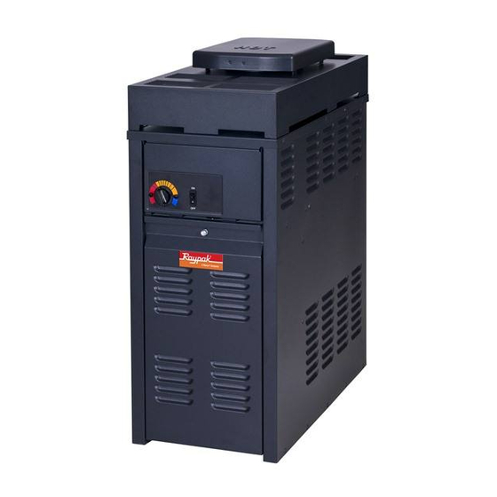
Above-Ground
Pool & Spa
Heater
Model 130A
WARNING: If the information in these instructions are not followed exactly, a fire or
explosion may result causing property damage, personal injury or death
FOR YOUR SAFETY: Do not store or use gasoline or other flammable vapors and
liquids or other combustible materials in the vicinity of this or any other appliance. To
do so may result in an explosion or fire.
WHAT TO DO IF YOU SMELL GAS:
• Do not try to light any appliance.
• Do not touch any electrical switch; do not use any phone in your building.
• Immediately call your gas supplier from a neighbor's phone. Follow the gas
supplier's instructions.
• If you cannot reach your gas supplier, call the fire department.
Installation and service must be performed by a qualified installer, service agency or
the gas supplier.
This manual should be maintained in legible condition and kept adjacent to the heater or in another safe place for
future reference.
CATALOG NO. 6100.59F
INSTRUCTIONS
Effective: 04-12-10
Replaces: 06-24-08
.
P/N 241255 Rev. 7
Advertisement
Table of Contents

Subscribe to Our Youtube Channel
Related Manuals for Raypak 130A


Summary of Contents for Raypak 130A
- Page 1 Above-Ground Pool & Spa Heater Model 130A WARNING: If the information in these instructions are not followed exactly, a fire or explosion may result causing property damage, personal injury or death FOR YOUR SAFETY: Do not store or use gasoline or other flammable vapors and liquids or other combustible materials in the vicinity of this or any other appliance.
- Page 2 Rev. 7 reflects the following: Changes to: Text formatting on pages 5 and 8, captions on Fig. 12 and Fig. 13 on page 13, winterizing instructions on page 21, IPL diagram on page 32, IPL information on pages 33 and 34.
-
Page 3: Table Of Contents
CONTENTS WARNINGS MAINTENANCE Pay Attention to These Terms SERVICE Water Pressure Switch WATER CHEMISTRY Automatic Chlorinators & Flame Roll-Out Safety Switch Chemical Feeders High Limits Pilot Safety—Millivolt Models SAFETY Water Temperature Safety Burner Tray Removal Gas Valve Removal INTRODUCTION Ratings & Certifications Main Burner &... -
Page 4: Warnings
WARNINGS - Pay Attention to These Terms Indicates the presence of immediate hazards which will cause severe DANGER: personal injury, death or substantial property damage if ignored. Indicates the presence of hazards or unsafe practices which could cause WARNING: severe personal injury, death or substantial property damage if ignored. Indicates the presence of hazards or unsafe practices which could cause CAUTION: minor personal injury or product or property damage if ignored. -
Page 5: Water Chemistry
WATER CHEMISTRY • Automatic chemical dosing devices and salt chlo- rinators are usually more efficient in heated water, unless controlled, they can lead to excessive chlo- NOTE: Corrosive water voids all warranties. rine level which can damage your heater. • Further advice should be obtained from your pool or spa builder, accredited pool shop, or chemical Chemical imbalance can cause severe damage to... -
Page 6: Safety
Heater Filter Auto-Chlorinator Pump Check Valve Skimmer Check Valve Pool Return to Pool Fig. 1: Pool/Chlorinator Setup SAFETY first three months of pregnancy resulting in the birth of a brain-damaged or deformed child. Pregnant women should stick to the 100°F (38°C) This appliance is to be installed and operated by maximum rule. -
Page 7: Model Identification
140 lbs. The model identification number and heater serial number are found on the heater rating plate. Table B: 130A Specifications Unpacking On receipt of the heater it is suggested that visual checks are made for external damage to the shipping carton. -
Page 8: Installation
INSTALLATION Clearances less than these may require removal of the heater to service either the heat exchanger or the burner tray. In either case, the heater must be installed Installation Codes in a manner that will enable the heater to be serviced without removing any structure around the heater. - Page 9 Fig. 4: 130A Dimensions Heater with Outdoor Stackless Top In areas of daily high winds, it may be necessary to replace the outdoor stackless top with a stack adapter in combination with a wind-resistant/weather-proof Heaters must not be installed under an overhang of outdoor stack.
-
Page 10: Indoor Installation
Indoor Installation All Air From Inside the Building Each opening shall have a minimum net free area of The heater is design-certified for indoor installation 130 sq. in. when equipped with the approved drafthood. All Air From Outdoors NOTE: For Canada, indoor installation is restricted to an enclosure that is not occupied and does not When air is supplied directly from outside of building, directly communicate with an occupied area. -
Page 11: Gas Connections
Minimum Minimum Minimum Minimum Minimum Minimum Forced Air Inlet Fig. 7: Outdoor Installation Clearances and inspection. Vent pipe should be adequately sup- ported to maintain proper clearances from combustible construction. Type "B" double-wall or equivalent vent pipe is recom- mended. However single-wall metal vent pipe may be used as specified in the latest edition of the National Flue Gas Code ANSI Z223.1 (Canada - CAN/CGA- B149). - Page 12 Gas Pressure Adjustment Locations Gas Pressure Adjustment (field supplied) (field supplied) Fig. 10A: Honeywell DSI VR 8205 Gas Valve (field supplied) Gas Pressure Adjustment Fig. 9: Gas Line Sediment Trap NOTE: Do not use Teflon tape on gas line pipe thread.
-
Page 13: Water Connections
Valve Manometer Model No. Min. gpm Max gpm* 130A *When flow rates exceed maximum 70 gpm, an external auxiliary bypass valve is required. See External Auxiliary Bypass Valve sec- tion for details. Table F: Water Flow Rates Gas Pressure Test at... - Page 14 High-temperature CPVC header flanges and header flange nuts are available as an option. If there is any From Heater possibility of back-siphoning when the pump stops, it is recommended that a check valve (or valves) also be installed in the system. Full Port Internal Automatic Bypass Valve Ball Valve...
-
Page 15: Electrical Connections
VAC input power hookup. Heater must be electrically grounded and bonded in accordance with local codes, or, in the absence of Table G: 130A Pressure Drop local codes, with the latest edition of the National Electrical Code, ANSI/NFPA 70. (Canada - Canadian Electrical Connections Electrical Code, CSA C22.1, Part 1 and Part 2.) -
Page 16: Control Adjustments-Millivolt
Control Adjustments—Millivolt Installation Instructions—240 Volt The pool or spa water temperature is controlled by the CAUTION: This appliance has provisions to be thermostat on the upper front panel of the heater. The connected to an alternate supply source. To reduce control center contains an On/Off toggle switch and a the risk of electric shock, disconnect all connections thermostat. -
Page 17: Wiring Diagrams
Wiring Diagrams HI Limit HI Limit Thermostat Manual Y/BK V/BK (In/Out) (In/Out) Switch To Firemans Switch (field installed) Optional Gas Valve Water Roll Out Press V/BK TH/PP Switch Switch Valve Pilot Generator Fig. 20: Wiring Diagram—Millivolt Models Fig. 21: Wiring Diagram—Electronic Models... - Page 18 FOR YOUR SAFETY READ BEFORE OPERATING WARNING: If you do not follow these instructions exactly, a fire or explosion may result causing property damage, personal injury or loss of life. *If you cannot reach your gas supplier, call the This appliance is equipped with an ignition fire department.
- Page 19 FOR YOUR SAFETY READ BEFORE OPERATING WARNING: If you do not follow these instructions exactly, a fire or explosion may result causing property damage, personal injury or loss of life. *If you cannot reach your gas supplier, call the This appliance has a pilot that must be lit by fire department.
-
Page 20: Post Start-Up Inspection
Post Start-Up Inspection Feel the inlet and outlet pipes. Outlet pipe should be only slightly warmer than the inlet. It should not be hot. Igniter WARNING: Should overheating occur or the gas Minimum Spark Gap is 0.15” - 0.18” supply fail to shut off, turn off the manual gas control 3/8”... -
Page 21: Maintenance
Winterizing the Pool/Spa Heater Yellow flame means restriction of the air openings. Lifting or blowing flame indicates high gas pres- sure. Low flame means low gas pressure. Should Heaters installed outdoors in freezing climate areas these occur, shut the heater off and contact your may be shut down for the winter. -
Page 22: Flame Roll-Out Safety Switch
High Limits 2. Turn adjustment knob counter-clockwise 1/4 turn. 3. Turn pump off and on several times. Heater should The heater is equipped with two automatic high limits. shut off immediately. If it does not, repeat the Both are located in the In/Out header. Both are set to above steps. - Page 23 4. Disconnect gas line from gas valve. 8. Remove (1) screw that mounts ground wire to burner tray. 5. Remove (2) screws that mount burner tray to unit, and (2) screws that secure gas valve to jacket. 9. Slide out burner tray. 6.
-
Page 24: Gas Valve Removal
Gas Valve Removal Igniter Removal & Cleaning (Electronic) 1. Remove burner tray from heater as described in the Burner Tray Removal section. 1. Disconnect high tension wire from igniter. 2. Disconnect pilot tubing (if removing a Millivolt 2. Remove (2) screws that mount the igniter to the valve). -
Page 25: Pilot Removal & Cleaning (Millivolt)
Pilot Removal & Cleaning 5. Disconnect all electrical wiring from in/out header. (Millivolt) 6. Remove temperature sensor from in/out header. 7. Disconnect flange nuts on In/Out header. Thermopile 8. Set aside heat exchanger side baffles. 9. Lift heat exchanger straight up using caution not to damage refractory. -
Page 26: Immersion Well Replacement-Millivolt
Replacement Parts 4. Remove heat exchanger from the heater and wash with a garden hose, making sure soot is removed from spaces between fins. NOTE: When ordering parts, it is important that the heater model number, serial number, and type of gas 5. -
Page 27: Troubleshooting Mechanical
TROUBLESHOOTING Mechanical These instructions are intended for use by qualified personnel who are specifically trained and experienced in the installation of this type of heating equipment and related system components. Installation and service per- sonnel may be required by some states to be licensed. Persons not qualified shall not attempt to install this equipment nor attempt repairs according to these instructions. -
Page 28: Electrical
Electrical Standing Pilot Millivolt The following information is presented for use by qualified service personnel only. 1. Filter must be on with adequate water flow through heater. 2. Gas valve must be in "ON" position. Thermostat set higher than pool water temperature. 3. - Page 29 Terminal Block Wiring Fig. 36: Terminal Block Wiring 1. Raw Output (700mV± 100) Pilot generator disconnected from valve (knob must be held down to keep pilot on). White – Negative Red + Positive 2. Pilot Load (500mV± 100) Pilot generator connected to valve-Power applied to pilot solenoid. TP(Thermopile-Robertshaw) PP(Power Pile-Honeywell) TH TP –...
-
Page 30: General-Heater Will Not Fire
Electronic Control Logic Flowchart START Turn knob to a desired temperature zone. Turn switch ON. •Check water flow. Pressure switch is set for 1.75 PSI. After (6) •Turn knob counterclockwise (setpoint may be lower seconds, does than actual temperature) the igniter •Check High Limit. -
Page 31: Illustrated Parts List
ILLUSTRATED PARTS LIST... - Page 32 HONEYWELL MILLIVOLT PILOT...
- Page 33 BURNER TRAY Burner Tray w/Burners (Sea Level)* 011578F 011578F Burner Tray w/o Burners (Sea Level)* 011579F 011579F Burner Tray w/Gas Valve Natural MV 011580F 011580F Burner Tray w/Gas Valve Propane MV 011581F 011581F Burner Tray w/Gas Valve Natural DSI 011582F 011582F Burner Tray w/Gas Valve Propane DSI 011583F...
- Page 34 MISCELLANEOUS COMPONENTS c t i Pressure Switch 11 PSI Special-See Adj in Service Manual 009133F 009133F l a i i l e PILOT c i f c i f REFRACTORY SHEETMETAL e l l t s l VENTING P " "...
Need help?
Do you have a question about the 130A and is the answer not in the manual?
Questions and answers