
Summary of Contents for Nikon HVBTR-1200
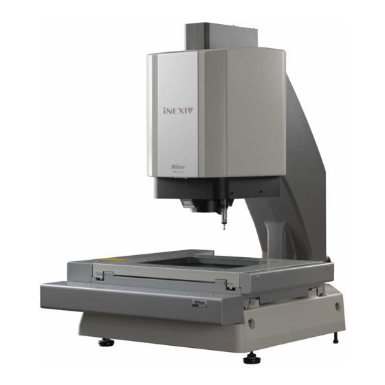
- Page 1 E163E 07.1.CF.1 *E163EN01* CNC Video Measuring System iNEXIV model VMA-2520 Instructions (Hardware)
-
Page 3: Warning Symbol Used In This Manual
“model VMA-2520”. To ensure correct usage, read this manual carefully before operating the instrument. • It is prohibited to reproduce or transmit this manual in part or whole without Nikon’s expressed permission. • The contents of this manual are subject to change without notice. -
Page 4: Meaning Of Symbols On The Product
Meaning of Symbols on the Product Symbol Explanation Caution! Moving Parts! This symbol on the stage reminds you of the following cautions: • Do not touch the main body or the stage while the equipment is in motion. Your hands or fingers could be caught in the machinery. •... - Page 5 Symbol Explanation When the optional “Laser Auto Focus” is installed, the entire system is CLASS 1 LASER PRODUCT classified as a Class 1 Laser product, and this label is visible on the front side of the lower head section. This label reminds you of the following cautions: •...
-
Page 6: Warning
The zoom head, guide, and scale are adjusted at the factory with extreme precision, so never attempt to disassemble them. If you notice a problem, contact your nearest Nikon representative. -
Page 7: Caution
If the input voltage is not identical to the supply voltage, do not attempt to connect the power but contact your nearest Nikon representative. Using the incorrect supply voltage could cause a malfunction, fire, or electric shock. -
Page 8: Cautions Concerning Use
Cautions Concerning Use Installation Location To avoid mis-operation and to peform safe and precise measurement, be sure to observe the following points when installing this system. Be especially careful not to pinch your fingers, etc., when installing the system. • Install the system in a clean environment. Dust and oily vapors can have a clear and adverse impact on the performance of the system. - Page 9 After restarting the system, even if it appears that everything is operating normally, be sure to “calibrate the optical head” and “check the Laser Autofocus focal position offset”. We also recommend that you have your nearest Nikon representative to inspect the system. USB and IEEE1394 setting Do not connect the supplied USB cable and IEEE1394 cable before the iNEXIV software is installed.
-
Page 10: Table Of Contents
Contents Warning Symbol Used in This Manual ......................i Meaning of Symbols on the Product ......................ii WARNING ............................iv CAUTION ............................v Cautions Concerning Use........................vi Chapter I. Names of Parts and Their Functions ...................1 General ........................1 Main Body/Measurement Stand ................2 Top View of Stage ......................3 System Layout ......................4 Controller ........................5... -
Page 11: Chapter I. Names Of Parts And Their Functions
Chapter I. Names of Parts and Their Functions General Display Joystick box Main body and stage section Rubber vibration isolator Measurement stand Controller Host computer - 1 -... -
Page 12: Main Body/Measurement Stand
Main Body/Measurement Stand (Distance between stroke-end sensors) (ストロークエンドセンサ間) WAR N I N G M a x i m u m p e r m i s s i b l e m a s s o n s t a g e : 1 5 k g O v e r c o n c e n t r a t i o n o f m a s s m a y b r e a k s t a g e g l a s s... -
Page 13: Top View Of Stage
Top View of Stage Measurement area 測定範囲 250 (Measurement area) 20-M6 Depth:10 20-M6深10 Maximum permissible mass: 15 kg The weight of clamps used for securing the workpiece should be taken into consideration. - 3 -... -
Page 14: System Layout
System Layout Host computer (rack) ホストPC(ラック) Outline of measurement stand 測定台外形 Outline of 本体外形 main unit Leg position 床支持位置 (leg diameter: 60) (脚直径∅60) - 4 -... -
Page 15: Controller
Controller Power switch Turns on and off the power of the main unit. | : ON ○ : OFF Status indicator LEDs Indicate the status of the controller. Fan motor HEAD connector Connect to the HEAD connector on the main body with the provided cable. -
Page 16: Joystick Box
Joystick Box STOP switch J/S connector Press this switch to stop all moving Connects to the J/S connector on the components. To resume operation, controller with the provided cable. restart the system. STOP VM A-J S Joystick Soft keys Use the joystick to move the Each soft key can be set with a workpiece in the X and Y directions function from the host computer. -
Page 17: Chapter Ii. System Setup
If there is a ridge or slope along the path over which the system is to be moved or if a truck or similar transport equipment is to be used, contact your Nikon representative in advance. Otherwise, Nikon shall not bear responsibility for any accidents or damage that occur while the system is being moved. -
Page 18: Setup Procedures
Setup Procedures Unpack the boxes. Open the product boxes at a location as close to the system installation site as possible, making sure that the area has no ridge and is not inclined. The boxes contain the main unit, controller and accessories, measurement stand (when the special measurement stand is used), host computer, etc. - Page 19 Detach the retaining fixtures from the stage (see the photo). Using a hexagonal wrench (4 mm), remove the red retaining fixtures from the two locations on the X axis and the location on the Y axis on the back side of the stage. Be careful not to apply excessive force to the stage when removing the retaining fixtures.
- Page 20 Level the system. If there is a protective material (blue plate) on the top surface of the stage, remove it. If the controller is to be set up on the shelf under the measurement stand, place the controller in position at this time. With the stage positioned near the center in both X and Y directions, place a level on the stage glass and adjust the height adjustment nuts on the adjustable legs of the measurement stand and main unit until the stage glass is level.
- Page 21 If the system still does not operate correctly after confirming all of the above items, stop using the system and contact your Nikon representative. (Note that the Nikon representative may ask you to check the status indicator LEDs on the rear panel of the controller.) 12) Connect the cables between the controller and host computer.
- Page 22 VMA Main Body HEAD ENCO DER M O TO R CASE VMA Controller M O TO R AC IN To AC power supply CASE IE E E1394 STO P IEEE1394 VM A -J S US B Host PC Joystick Unit - 12 -...
- Page 23 If the system still does not operate correctly after confirming all of the above items, stop using the system and contact your Nikon representative. 15) Calibrate the optical head. Before conducting measurement, perform calibrations (1) through (3) described below. It is recommended that these calibrations be performed regularly (about once a month).
-
Page 24: Chapter Iii. Operation
Chapter III. Operation Basically, this system is operated through the host computer. For details on making measurements, refer to the instruction manual for the “VMA Automeasure.” This chapter explains how to turn the system on and off, how to clean the system, and how to lubricate. Turning the Power On and Off Power ON: Turn on the power switch on the front of the controller. -
Page 25: Chapter Iv. Performance And Specifications
Chapter IV. Performance and Specifications Style Type: Single-column X-Y stage type • Dimensions (W × D × H) • Main body: 565 × 690 × 740 mm (in clamped condition) Controller: 145 × 400 × 390 mm Joystick box: 100 × 177 × 98 mm Special measurement table: 650 ×... -
Page 26: Sections
Sections X-Y stage section • Effective stroke: 250 × 200 mm Size of stage: 500 × 400 mm Size of stage glass: 280 × 230 mm Workpiece mass for which precision is guaranteed: 5 kg Workpiece mass for load bearing capacity is guaranteed: 15 kg Maximum permissible mass on stage glass: 15 kg Z-axis motion section... -
Page 27: Measurement Accuracy
Measurement Accuracy Total accuracy (X, Y axes) • When a traceable standard scale or a conforming evaporation pattern is placed on the stage glass and is measured with a fixed zoom position, at the center of the viewfield (“L” represents any measured length in mm) Repeatability (when magnification is 3.5 ×... -
Page 28: Electrical Standards
Electrical Standards Input ratings (controller) • Input supply voltage: 100 to 240 V AC (automatic switching) Input supply voltage: 50/60 Hz Current consumption: 5A to 2.5A Supply voltage fluctuation: within ± 10% Electric shock protection class: Class 1 (grounded connection type) •... - Page 29 Symbol for separate collection applicable in European countries Symbol for kildesortering i europeiske land This symbol indicates that this product is to be collected separately. Dette symbolet indikerer at produktet skal kildesorteres. The following apply only to users in European countries. De nedenstående punktene gjelder for alle europeiske brukere.
- Page 30 Tel: +1-631-547-8500 Fax: +1-631-547-0306 Semiconductor Inspection Technologies Division 1430 W. Auto Drive, Suite 101, Tempe, AZ 85284, U.S.A. Tel: +1-480-403-4100 Fax: +1-480-403-4199 NIKON INSTRUMENTS EUROPE B.V. Schipholweg 321, P.O. Box 222, 1170 AE Badhoevedorp, The Netherlands Tel: +31-20-44-96-222 Fax: +31-20-44-96-298...