Advertisement
Quick Links
Advertisement

Subscribe to Our Youtube Channel
Related Manuals for RODE Microphones Broadcaster


Summary of Contents for RODE Microphones Broadcaster
- Page 1 Broadcaster Instruction Manual www.rodemic.com ( EMC, LVD )
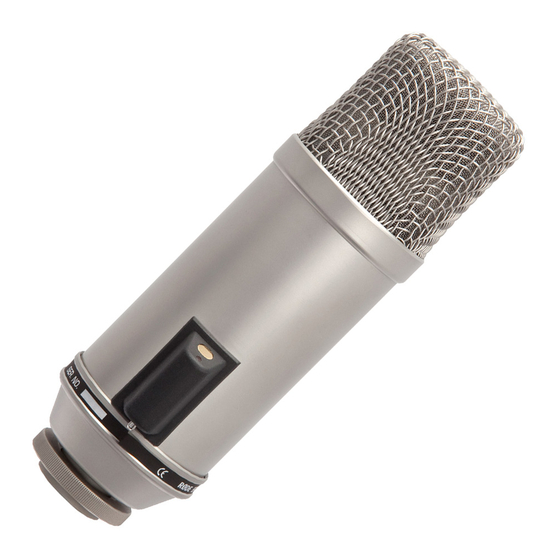
- Page 2 Utilising an Australian designed and manufactured 1” externally biased condenser transducer, the Broadcaster features a switchable high-pass fi lter to remove low frequency rumble. A unique ‘ON-AIR’ LED indicator can be switched on or off by shorting contacts on the fi...
-
Page 3: Specifications
Specifi cations Acoustic Pressure gradient Principle: Directional Cardioid- end address Pattern: Frequency 20 Hz-20 kHz Range: Output 40 Impedence: Sensitivity: -34 dB re 1 Volt/Pascal (20 mV @ 94 dB SPL) +/- 2 dB @ 1kHz Equivalent Noise: 14 dB SPL (A - weighted per IEC651) Maximum +2dBu... -
Page 4: Frequency Response
Specifi cations Frequency Response High Pass Filter Polar Response 0˚ +5.0 -2.0 -2.0 -4.0 -6.0 -8.0 -10.0 -10.0 -12.0 -14.0 -16.0 -18.0 -20.0 -20.0 -22.0 -24.0 90˚ 270˚ -25.0 dB rel. 1V/Pa – Frequency: – 500 Hz: – 1000 Hz: 4000 Hz: 180˚... - Page 5 Accessories • RM2 stand mount • 5 pin ‘on-air’ indicator adaptor • ZP1 zip pouch - 5 -...
- Page 6 This will ensure the highest quality sound reproduction. • The Broadcaster is an ‘end address’ microphone, so should be addressed with the microphone mounted lengthways, talking directly in to the head.
- Page 7 Using the Broadcaster • The High Pass Filter can be engaged using the toggle switch at the rear of the microphone. BROADCASTER SIDE VIEW High Pass Filter toggle switch Flat High Pass Filter engaged BROADCASTER BOTTOM VIEW - 7 -...
- Page 8 Connecting the ‘on-air’ LED • While the broadcaster’s output connection and ‘On-Air’ indicator control is a very simple operation to perform, we suggest that unless you are familiar with cable connections and audio installations in general, that you have an Audio/Electronics Technician perform this task to assure optimum performance.
- Page 9 Connecting the ‘on-air’ LED • A 5-pin female connector is supplied, and you can use a four-core screened (Quad) microphone cable which is readily available from most professional audio suppliers, or you can use any cable which is two wire screened plus two extra control wires if the LED is to be switched.
-
Page 10: Circuit Diagram
Circuit Diagram - 10 -... - Page 11 Storage • After use the Broadcaster should be removed from its mount, wiped with a dry, soft cloth and placed in its protective case. • Be sure to place the moisture-absorbent crystals (supplied) at the head of the microphone, so as to absorb any moisture present.
-
Page 12: Warranty
Warranty microphones are warranted for one year from date of purchase. You can extend that to a full ten years if you register online at www.rodemic.com. The warranty covers parts and labour that may be required to repair the microphone during the warranty period.
Need help?
Do you have a question about the Broadcaster and is the answer not in the manual?
Questions and answers