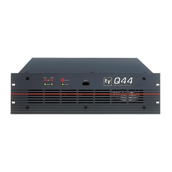
Electro-Voice Q44 Owner's Manual
Professional amplifier
Hide thumbs
Also See for Q44:
- Specifications (4 pages) ,
- Owner's manual (28 pages) ,
- Brochure & specs (8 pages)
Advertisement
Advertisement
Table of Contents

Summary of Contents for Electro-Voice Q44
- Page 1 Q44/Q66 PROFESSIONAL AMPLIFIER OWNER’S MANUAL...
-
Page 2: Important Safety Instructions
IMPORTANT SAFETY INSTRUCTIONS The lightning flash with arrowhead symbol, within an equilateral triangle is intended to alert the user to the presence of uninsulated “dangerous voltage” within the product’s enclosure that may be of sufficient magnitude to constitute a risk of electric shock to persons. - Page 3 DESCRIPTION C O N T E N T S Description ............3 Front Panel .
-
Page 4: Front Panel
FRONT PANEL 1. LIMIT This indicator lights when the amplifier enters clipping and the internal limiter is activated. Short-term indication is problem-free. Anyway, if this indicator lights continuously, reducing the overall volume is recommended to avoid that the connected loudspeaker systems are getting damaged from overload. -
Page 5: Rear Panel
REAR PANEL P O W E R A M P L I F I E R I N P U T S Parallel to the XLR-type inputs, XLR-type output connectors are provided, offering the opportunity to feed additional power amplifiers with the same signal. The inputs are electrically balanced with pin-assignment according to the IEC 268 standard. -
Page 6: Ground-Lift Switch
REAR PANEL Power Amplifier Outputs The power amplifier’s channel A (left) and channel B (right) outputs are carried out as SPEAKON output connectors. The bridged-out connector conducting the output signal in bridged mode operation is protected by a plastic cover to avoid inadvertently plugging a speaker cable into the wrong connector. -
Page 7: Specifications
SPECIFICATIONS Technical Specifications: Q44, Q66 Amplifier at rated conditions, both channels driven with 8 ohms loads, unless otherwise specified. Ω Ω Ω Ω Ω Ω Load Impedance M aximum Midband Output Power 280W 450W 650W 380W 600W 850W THD=1%, 1kHz... -
Page 8: Block Diagram
BLOCK DIAGRAM... - Page 9 DIMENSIONS Dimensions (in mm)
- Page 10 NOTES...
- Page 11 NOTES...
- Page 12 NOTES...
- Page 13 WARRANTY (Limited) Electro-Voice products are guaranteed against malfunction due to defects in materials or workmanship for a specified period, as noted in the individual product-line statement(s) below, or in the individual product d ata sheet or owner’s manual, beginning with the date of original purchase.


Need help?
Do you have a question about the Q44 and is the answer not in the manual?
Questions and answers