Table of Contents
Advertisement
Available languages
Available languages
Advertisement
Table of Contents

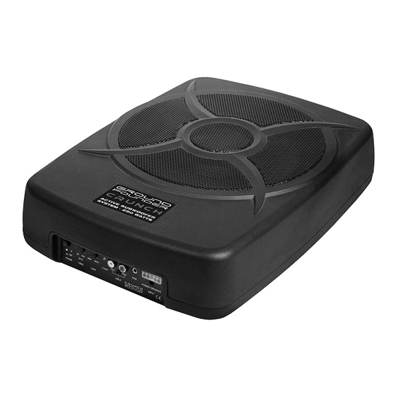
Summary of Contents for Crunch GP808
- Page 1 GP808 · GP810 ACTIVE SUBWOOFER SYSTEM BENUTZERHANDBUCH OWNER‘S MANUAL...
-
Page 2: Allgemeine Hinweise
Produkt mit einem gültigen Kaufbeleg und einer detaillierten Fehlerbeschreibung an Ihren Fachhändler, bei dem Sie das Produkt erworben haben. Alle Crunch Geräte sind mit einer CE-Kennzeichnung versehen. Damit sind die Geräte für den Betrieb in Fahrzeugen innerhalb der Europäischen Union (EU) zertifiziert. - Page 3 SICHERHEITSHINWEISE BITTE BEACHTEN SIE DIE FOLGENDEN HINWEISE VOR INBETRIEBNAHME! DAS VON IHNEN ERWORBENE GERÄT IST NUR FÜR DEN BETRIEB DAS GERÄT NICHT AN STELLEN EINBAUEN, AN DENEN ES HOHER AN EINEM 12-V-BORDNETZ EINES FAHRZEUGS AUSGELEGT. An- FEUCHTIGKEIT ODER STAUB AUSGESETZT IST. Bauen Sie das Ge- dernfalls besteht Feuergefahr, die Gefahr eines elektrischen Schlages oder rät so ein, dass es vor hoher Feuchtigkeit und Staub geschützt ist.
-
Page 4: Mechanische Installation
INSTALLATIONSHINWEISE HINWEIS Bevor Sie mit der Installation des Soundsystems beginnen, trennen Sie unbedingt den Massepol der Fahrzeugbatterie ab, um Kurzschlüsse und Stromschläge zu vermeiden. MECHANISCHE INSTALLATION Achten Sie bei der Installation darauf, dass keine serienmäßig im KFZ vorhandenen Teile wie z.B. Kabel, Bordcomputer, Sicherheitsgur- te, Tank oder ähnliche Teile beschädigt bzw.entfernt werden. -
Page 5: Elektrische Anschlüsse
INSTALLATIONSHINWEISE ELEKTRISCHE ANSCHLÜSSE 0° POWER/SPEAKER (Hz) POWER 180° INPUT PHASE FREQ GAIN INPUT BEILIEGENDER KABELBAUM MIT STECKER GELB SCHWARZ BLAU-WEISS 0° POWER/SPEAKER (Hz) POWER 180° INPUT PHASE FREQ GAIN INPUT VOR DEM ANSCHLIESSEN Säubern und entfernen Sie vorhandene Rost- und Oxidationsstellen an allen Kontaktpunkten der Batterie und an den Massepunkten. Ziehen Sie nach der Installation alle Schrauben fest an, denn ein lockerer Anschluss kann eine Fehlfunktion, unzureichende Stromver- sorgung oder Störgeräusche sowie Verzerrungen zur Folge haben. -
Page 6: Funktionen Und Bedienelemente
FUNKTIONSHINWEISE FUNKTIONEN UND BEDIENELEMENTE 0° POWER/SPEAKER (Hz) POWER 180° INPUT PHASE FREQ GAIN INPUT BEILIEGENDER KABELBAUM MIT STECKER BEILIEGENDES GRAU / GRAU-SCHWARZ KABEL MIT STECKER WEISS / WEISS-SCHWARZ Der PHASE-Tastschalter erlaubt die Umkehrung der Phasenlage von 0° auf 180°. Dadurch kann der Subwoofer an die Fahr- zeugakustik angepasst werden. -
Page 7: Fehlerbehebung
FEHLERBEHEBUNG Fehler: keine Funktion, keine Power LED leuchtet Ursache: Lösung: 1. Die Stromversorgungskabel sind nicht korrekt angeschlossen. Erneute Überprüfung 2. Die Kabel haben keinen elektrischen und mechanischen Kontakt. Erneute Überprüfung 3. Die Remote-Steuerleitung des Steuergeräts (Autoradio) ist nicht korrekt am Gerät angeschlossen. Erneute Überprüfung 4. -
Page 8: General Notes
Please return the defective product only with a valid proof of purchase and a detailed malfunction description to your retail store, where you have purchased this product. All Crunch devices are labeled with a CE-Certification Mark. Thereby these devices are certified for a use inside vehicles inside the European Union (EU). -
Page 9: Safety Instructions
SAFETY INSTRUCTIONS PLEASE NOTE THE FOLLOWING ADVICES BEFORE THE FIRST OPERATION! THE PURCHASED DEVICE IS ONLY SUITABLE FOR AN OPER-ATION DO NOT INSTALL THE DEVICE AT LOCATIONS, WHERE IT WILL BE WITH A 12V ON-BOARD ELECTRICAL SYSTEM OF A VEHICLE. Other- EXPOSED TO HIGH HUMIDITY AND DUST. -
Page 10: Installation Instructions
INSTALLATION INSTRUCTIONS NOTE Before you start with the installation of the sound system, disconnect necessarily the GROUND connection wire from the battery to avoid any risk of electric shocks and short circuits. MECHANICAL INSTALLATION Avoid any damages on the components of the vehicle like air bags, cables, board computer, seat belts, gastank or the like. Ensure that the chosen location provides a sufficient air circulation for the sound system. -
Page 11: Electrical Interconnection
INSTALLATION INSTRUCTIONS ELECTRICAL INTERCONNECTION 0° POWER/SPEAKER (Hz) POWER 180° INPUT PHASE FREQ GAIN INPUT ENCLOSED WIRING HARNESS WITH PLUG YELLOW BLACK BLUE-WHITE 0° POWER/SPEAKER (Hz) POWER 180° INPUT PHASE FREQ GAIN INPUT BEFORE CONNECTING Clean and remove rust-streaked and oxidized areas on the contact points of the battery and the ground connection. Make sure that all screws are fixed tight after the installation, because loose connections cause malfunctions, insufficient power supply or interferences. -
Page 12: Functional Instructions
FUNCTIONAL INSTRUCTIONS FEATURES AND OPERATIONAL CONTROLS 0° POWER/SPEAKER (Hz) POWER 180° INPUT PHASE FREQ GAIN INPUT ENCLOSED WIRING HARNESS WITH PLUG ENCLOSED GREY / GREY-BLACK CABLE WITH PLUG WHITE / WHITE-BLACK The PHASE push button allows to switch the phase from 0° to 180°. Hence, you are able to adjust the subwoofer perfect to the 0°... - Page 13 Malfunction: no function, no power LED Reason: Remedy: 1. The power supply connection of the device is not correct Recheck 2. The cabels have no mechanical or electrical contact Recheck 3. The remote turn-on connection from the head unit to the device is not correct Recheck 4.
- Page 14 NOTES...
- Page 15 NOTES...
- Page 16 Audio Design GmbH Am Breilingsweg 3 · D-76709 Kronau/Germany Tel. +49(0)7253 - 9465-0 · Fax +49(0)7253 - 946510 www.audiodesign.de ©2014 Audio Design GmbH, All Rights Reserved...


Need help?
Do you have a question about the GP808 and is the answer not in the manual?
Questions and answers