Table of Contents
Advertisement
Advertisement
Table of Contents

Subscribe to Our Youtube Channel
Related Manuals for Sea-doo 2004 3d rfi


Summary of Contents for Sea-doo 2004 3d rfi
- Page 1 www.SeaDooManuals.net...
- Page 2 2004 Shop Manual Supplement BOMBARDIER RECREATIONAL PRODUCTS INC. www.SeaDooManuals.net...
- Page 3 ® BOMBARDIER* LUBE ® XP-S Synthetic Injection Oil XP-S Synthetic Blend Injection Oil XP-S Mineral Injection Oil Sea-Doo Synthetic Grease Sea-Doo LK DESS O.P.A.S. TOPS O.T.A.S. This document contains the trademarks of the following companies: Knight’s Spray-Nine † is a trademark of Korkay System Ltd †...
-
Page 4: Table Of Contents
TABLE OF CONTENTS NOTE: Refer to shop manual for sections NOT covered in this supplement. SAFETY NOTICE ................. .. INTRODUCTION .. - Page 5 TABLE OF CONTENTS FUEL SYSTEM 01 – FUEL CIRCUIT ....................31 LUBRICATION SYSTEM (2-STROKE) 02 –...
-
Page 6: Safety Notice
This manual has been prepared as a guide to correctly service and repair the 2004 3D SEA-DOO watercraft. This Shop Manual Supplement must be used in conjunction with the 2004 Sea-doo Shop Manual (P/N 219 100 192). Refer to this manual when a particular system is not covered in this Supple- ment. - Page 7 SAFETY NOTICE BRP disclaims liability for all damages and/or injuries resulting from the improper use of the contents. We strongly recommend that any services be carried out and/or verified by a highly skilled professional mechanic. It is understood that certain modifications may render use of the vehicle illegal under existing federal, provincial and state regulations.
-
Page 8: Introduction
INTRODUCTION INTRODUCTION ENGINE IDENTIFICATION This Shop Manual Supplement covers the follow- ing BRP made SEA-DOO ® 2004 3D NUMBER (E.I.N.) tercraft models. The Engine Identification Number is located on the upper crankcase on PTO side. ENGINE MODEL MODEL TYPE NUMBER... -
Page 9: Maintenance
Section 02 MAINTENANCE Subsection 01 (PERIODIC INSPECTION CHART) PERIODIC INSPECTION CHART The schedule should be adjusted according to operating conditions and use. NOTE: The chart gives an equivalence between number of hours and months/year. Perform the mainte- nance operation to whatever time comes first. IMPORTANT: Schedule for watercraft rental operations or higher number of hour use, will require greater frequency of inspection and maintenance. - Page 10 Section 02 MAINTENANCE Subsection 01 (PERIODIC INSPECTION CHART) DESCRIPTION INTERVAL I: Inspect, verify, clean, adjust, lubricate. EVERY EVERY EVERY Replace if necessary FIRST 25 HOURS 50 HOURS 100 HOURS C: Clean L: Lubricate HOURS 3 MONTHS 6 MONTHS 1 YEAR R: Replace LUBRICATION SYSTEM Oil injection pump (5)
- Page 11 Section 02 MAINTENANCE Subsection 01 (PERIODIC INSPECTION CHART) DESCRIPTION INTERVAL I: Inspect, verify, clean, adjust, lubricate. EVERY EVERY EVERY Replace if necessary FIRST 25 HOURS 50 HOURS 100 HOURS C: Clean L: Lubricate HOURS 3 MONTHS 6 MONTHS 1 YEAR R: Replace HULL/BODY Bailer pick-ups, check for obstructions...
-
Page 12: Storage
Push and hold hose against bilge so that draining proper procedure. can take place. CAUTION: Use only SEA-DOO jet pump oil or NOTE: It may be necessary to position the end of equivalent synthetic gear oil, otherwise com- the hose in a lower area of the bilge to allow proper ponent service life could be reduced. -
Page 13: Fuel System
NOTE: On the 3D RFI, the hose adapter is located Sea-Doo Fuel Stabilizer (P/N 413 408 600) or equiv- on the right hand side on the jet pump support. alent should be added in fuel tank to prevent fuel deterioration. -
Page 14: Battery
Section 02 MAINTENANCE Subsection 04 (STORAGE) BATTERY Engine and Tuned Pipe Remove rear access panel and engine cover. Lock Disconnect battery cables. steering pole in upright position with the holder. WARNING WARNING Battery BLACK negative cable must be dis- Always install steering pole holder while connected FIRST. -
Page 15: Anticorrosion Treatment
Section 02 MAINTENANCE Subsection 04 (STORAGE) Expansion Pipe and Muffler Insert a funnel into the temporary hose and pour antifreeze in engine until the colored solution ap- Disconnect the tuned pipe water supply hose at pears at the cooling system bleed outlet. Use a T-fitting. -
Page 16: Troubleshooting
Section 03 TROUBLESHOOTING Subsection 01 (TROUBLESHOOTING CHART) TROUBLESHOOTING CHART The following is provided to help in diagnosing the probable source of troubles. It is a guideline and should not be assumed to show all causes for all problems. Only the systems not covered in the Shop Manual are outlined. -
Page 17: Warning Light Is On/Engine Not Running
Section 03 TROUBLESHOOTING Subsection 01 (TROUBLESHOOTING CHART) WARNING LIGHT IS ON/ENGINE NOT RUNNING OTHER OBSERVATION POSSIBLE CAUSE REMEDY Beeper signal (4 short Safety lanyard on DESS post Remove safety lanyard from DESS post beeps every 3 seconds) STEERING POLE IS HEAVIER THAN USUAL OTHER OBSERVATION POSSIBLE CAUSE REMEDY... -
Page 18: Engine (2-Stroke)
Section 04 ENGINE (2-STROKE) Subsection 07 (EXHAUST SYSTEM) EXHAUST SYSTEM 3D RFI 48 N•m (35 lbf•ft) Loctite 592 Loctite 592 11 N•m (97 lbf•in) 26 N•m (19 lbf•ft) Loctite 592 26 N•m (19 lbf•ft) Loctite 518 26 N•m (19 lbf•ft) 39 N•m (29 lbf•ft) Loctite 592... - Page 19 Section 04 ENGINE (2-STROKE) Subsection 07 (EXHAUST SYSTEM) High temperature RTV sealant High temperature RTV sealant Loctite 5150 High temperature RTV sealant F22D04S smr2004-3D www.SeaDooManuals.net...
-
Page 20: Removal
Section 04 ENGINE (2-STROKE) Subsection 07 (EXHAUST SYSTEM) REMOVAL Tuned Pipe Remove engine cover then lift and lock steering pole. Remove air intake silencer. NOTE: In some of the following illustrations, flame arrester and throttle body were removed for clarity only. Disconnect hoses from tuned pipe no. - Page 21 Section 04 ENGINE (2-STROKE) Subsection 07 (EXHAUST SYSTEM) Exhaust Manifold – screw no. 4 and 5. Disconnect hose from exhaust manifold no. 25. F22D08A F22D05D Remove screws no. 7 then withdraw exhaust manifold. Expansion Pipe Inspection Do the test with the watercraft tied on a trailer in water.
- Page 22 Section 04 ENGINE (2-STROKE) Subsection 07 (EXHAUST SYSTEM) WARNING Pay attention not to bend injection oil cable or throttle cable. – hoses from rear fittings no. 11 F22D0DA 1. Hose moved away 2. Foam support F22D0CA 1. Disconnect hoses from fittings here –...
- Page 23 Section 04 ENGINE (2-STROKE) Subsection 07 (EXHAUST SYSTEM) F22D0HA F22D0FA Muffler – rotate left/right as shown Pull muffler out. Inspect muffler, shell and boot condition. Resonators Upper Resonator Remove strap no. 8, loosen clamps no. 9 then pull out resonator no. 10. F22D0GA –...
-
Page 24: Installation
Section 04 ENGINE (2-STROKE) Subsection 07 (EXHAUST SYSTEM) F22D0BA INSTALLATION Installation is essentially the reverse of removal procedures. However, pay particular attention to the following. Tuned Pipe CAUTION: Torque wrench tightening specifi- cations must be strictly adhered to. Locking devices (ex.: locking tabs, elastic stop nuts, self-locking fasteners, etc.) must be installed or replaced with new ones where specified. - Page 25 Section 04 ENGINE (2-STROKE) Subsection 07 (EXHAUST SYSTEM) NOTE: Press the pipe support on the engine before torquing the pipe support bolts. 26 N•m (19 lbf•ft) 26 N•m (19 lbf•ft) 26 N•m 1 N•m (19 lbf•ft) (9 lbf•in) 26 N•m 40 N•m (19 lbf•ft) (30 lbf•ft)
- Page 26 Section 04 ENGINE (2-STROKE) Subsection 07 (EXHAUST SYSTEM) Expansion Pipe and Muffler Apply Loctite 592 on threads of fittings no. 11. Tighten fittings to 5 N•m (44 lbf•in) then position as per following illustration. Do not screw more than 1 turn while positioning. Do not unscrew to reposition.
- Page 27 Section 04 ENGINE (2-STROKE) Subsection 07 (EXHAUST SYSTEM) To ensure pipe end is well inserted in muffler, measure the distance as shown in the following illustration. F22D0KS A. 322 mm (12.68 in) Insert foam under expansion pipe. Ensure foam – Ensure there is a gap between clamp ends. is not against muffler bellow.
-
Page 28: Exhaust Outlet
Section 04 ENGINE (2-STROKE) Subsection 07 (EXHAUST SYSTEM) F22D0PA F22D0NA 1. All around 2. Opposite vertical lines A. Gap between hose and fuel tank Ensure there is a gap between muffler and Finalizing Assembly bilge/cooling hose. WARNING Ensure that tubes and hoses are properly routed away from any rotating, moving, heating or vibrating parts. -
Page 29: Engine Management (Rfi)
Section 06 ENGINE MANAGEMENT (RFI) Subsection 02 (DIAGNOSTIC PROCEDURES ) DIAGNOSTIC PROCEDURES ADVANCED DIAGNOSTIC After all connections are done, connect the safety lanyard to the DESS post to activate the commu- VCK (Vehicle Communication Kit) nication. IMPORTANT: When using the software B.U.D.S., Electrical Connections ensure that the protocol matching the connec- Connect VCK components and open the software... -
Page 30: Adjustment
Section 06 ENGINE MANAGEMENT (RFI) Subsection 05 (ADJUSTMENT) ADJUSTMENT THROTTLE CABLE ADJUSTMENT NOTE: For throttle cable replacement, refer to STEERING SYSTEM. Right throttle cable adjustment is to be done at the adjuster on top of steering pole. However, first ensure adjuster at throttle body is fully screwed F22K09A 1. - Page 31 Section 06 ENGINE MANAGEMENT (RFI) Subsection 05 (ADJUSTMENT) When released, throttle lever must have a free play of 1 - 7 mm (1/32 - 9/32 in). To adjust cable, remove top cover of steering pole. Refer to STEERING SYSTEM. Set cable with the adjuster. F22R05A 1.
-
Page 32: Cooling System
Section 09 COOLING SYSTEM Subsection 01 (CIRCUIT, COMPONENTS AND CARE) CIRCUIT, COMPONENTS AND CARE 3D RFI Cooling System Indicator hose Magneto view (CSI) Tuned pipe water To crankcase heat jacket supply hose exchanger inlet To tunel Magneto heat pipe exchanger inlet hose Magneto heat exchanger... -
Page 33: Circuit
The water from the expansion pipe water jacket is injected into the muffler to cool it (last part of the Special precautions should be taken when towing expansion pipe water jacket has internal holes). a Sea-Doo 3D watercraft in water. Maximum recommended towing... - Page 34 Section 09 COOLING SYSTEM Subsection 01 (CIRCUIT, COMPONENTS AND CARE) Snugly install the hose pincher on the water sup- ply hose as shown in the following illustration. NOTE: Pinch the hose with the red tape. F22E01A 1. Engine water supply hose 2.
-
Page 35: Fuel System
Section 10 FUEL SYSTEM Subsection 01 (FUEL CIRCUIT) FUEL CIRCUIT Fuel Tank Removal and Installation To have access to the rear fuel tank holding strap, remove exhaust hoses with the resonator. The engine removal is necessary to remove fuel tank. Disconnect battery. - Page 36 Section 10 FUEL SYSTEM Subsection 01 (FUEL CIRCUIT) Fuel System Pressurization High Pressure Test (fuel pump circuit) Proceed as follows: Install safety lanyard on DESS post to activate fuel pump. Check for any leakage at fuel rail, injectors – Fill up fuel tank (recommended but not manda- and fuel hose.
-
Page 37: Lubrication System (2-Stroke)
Section 11 LUBRICATION SYSTEM (2-STROKE) Subsection 02 (OIL INJECTION PUMP) OIL INJECTION PUMP ADJUSTMENT NOTE: On the 3D RFI, if the throttle cable is read- justed, it does not change the oil injection pump adjustment. CAUTION: Proper oil injection pump adjust- ment is very important. -
Page 38: Electrical System
Section 12 ELECTRICAL SYSTEM Subsection 02 (CHARGING SYSTEM) CHARGING SYSTEM GENERAL Fuse If the battery is regularly discharged, check fuse condition. The rectifier/regulator could be the culprit of a blown fuse. To check, simply disconnect the rectifier/regulator from the circuit. If the fuse still burns, check for a defective wire. - Page 39 Section 12 ELECTRICAL SYSTEM Subsection 02 (CHARGING SYSTEM) – Note the reading. This is the current supplied If multimeter reads over 15 volts, regulator is de- by the regulator. fective. Replace it. – Remove jumper wire and reconnect the 2-pin NOTE: If it is continually necessary to add distilled connector.
- Page 40 Section 12 ELECTRICAL SYSTEM Subsection 02 (CHARGING SYSTEM) Start and rev engine to 3500 RPM. The obtained value should be between 12 and 25 Vdc. NOTE: If the rectifier/regulator is within the spec- ification, either the MPEM or wiring harness be- tween the rectifier and battery is defective.
-
Page 41: Starting System
Section 12 ELECTRICAL SYSTEM Subsection 03 (STARTING SYSTEM) STARTING SYSTEM GENERAL Fuse Make sure the following fuses are in good condi- tion. 5 A fuse on the MPEM. Main fuse besides the VCM. F22H02B 1. VCM 2. Main fuse 3. Starting solenoid Solenoid NOTE: Solenoid is located besides the VCM. -
Page 42: Instruments And Accessories
Section 12 ELECTRICAL SYSTEM Subsection 04 (INSTRUMENTS AND ACCESSORIES) INSTRUMENTS AND ACCESSORIES GENERAL Using a voltmeter, perform the following test: Connect one test probe to the harness connector Install safety lanyard to activate MPEM and VCM at pin 26 and the other probe to the battery ground. to perform testing procedures that requires the device to be supplied with electricity. - Page 43 Section 12 ELECTRICAL SYSTEM Subsection 04 (INSTRUMENTS AND ACCESSORIES) As a reserve indicator, the beeper will turn on NOTE: Perform the voltage reading quickly be- when approximately 6 L (1.6 U.S. gal.) is left and fore the VCM stops sending the test signal to the the low level light will continuously blink.
- Page 44 Section 12 ELECTRICAL SYSTEM Subsection 04 (INSTRUMENTS AND ACCESSORIES) – The O.T.A.S. should come on for 1/2 second and increase engine RPM within 2900 to 3900. – If steering is kept in this position, the O.T.A.S. will come on again every 2 seconds. –...
- Page 45 Section 12 ELECTRICAL SYSTEM Subsection 04 (INSTRUMENTS AND ACCESSORIES) Disconnect the switch 4-pin connector. O.T.A.S. Throttle Cable Adjustment WARNING Whenever solenoid or throttle cable has been replaced, ensure to perform the O.T.A.S throt- tle cable adjustment. Strictly follow the de- scribed procedure.
-
Page 46: Multi-Purpose Electronic Module (Mpem)
Section 12 ELECTRICAL SYSTEM Subsection 04 (INSTRUMENTS AND ACCESSORIES) NOTE: In BUDS, position and hold the mouse pointer over the needle of the throttle opening to get the actual value. F22H0BB 1. OTAS solenoid 2. Adjust here MULTI-PURPOSE ELECTRONIC MODULE (MPEM) The MPEM is powered by the battery through the VCM. - Page 47 Section 12 ELECTRICAL SYSTEM Subsection 04 (INSTRUMENTS AND ACCESSORIES) Always ensure safety lanyard is not left on its post Overheat Sensor after engine is stopped. When the engine temperature reaches a threshold IMPORTANT: Leaving the safety lanyard on its value, the MPEM triggers a continuous beep to post when engine is not running will slowly dis- indicate overheating.
-
Page 48: Inspection
Section 12 ELECTRICAL SYSTEM Subsection 04 (INSTRUMENTS AND ACCESSORIES) Fuse ratings are identified on the MPEM. Look for Main Fuse them beside the fuse holder. SPR means spare The main fuse is located beside the VCM. (fuse). F22H02A 1. VCM 2. - Page 49 Section 12 ELECTRICAL SYSTEM Subsection 04 (INSTRUMENTS AND ACCESSORIES) The resistance measured between PINK/BLACK When the oil level goes at critical LOW level inside and PINK wires must be in accordance with fuel the oil tank (and therefore in sensor reservoir), the level (measured from under the flange) as speci- sensor detects the absence of liquid and the light fied in the following charts.
-
Page 50: Dess (Carbureted And Rfi Engines)
Section 12 ELECTRICAL SYSTEM Subsection 05 (DESS (CARBURETED AND RFI ENGINES)) DESS (CARBURETED AND RFI ENGINES) DESS KEY PROGRAMMING After all connections are done, connect the safety lanyard to the DESS post to activate the commu- Programming Keys with B.U.D.S. nication. -
Page 51: Propulsion
Section 13 PROPULSION Subsection 01 (JET PUMP) JET PUMP Impeller Identification F02J0VA 1. Stamped part number WATERCRAFT IMPELLER MATERIAL PITCH MODEL Progressive Stainless 3D RFI 271 001 496 pitch steel 11° - 20° smr2004-3D www.SeaDooManuals.net... -
Page 52: Drive System
Section 13 PROPULSION Subsection 02 (DRIVE SYSTEM) DRIVE SYSTEM F22J09S smr2004-3D www.SeaDooManuals.net... -
Page 53: Removal
Section 13 PROPULSION Subsection 02 (DRIVE SYSTEM) REMOVAL Rear Drive Shaft Remove rear access panel. PTO Flywheel Guard Remove clamps from exhaust hoses where Lift and lock steering pole, remove hood and re- shown. move storage tray. Pull out T-fitting with hoses and resonator. Pull down vent tubes from body. - Page 54 Section 13 PROPULSION Subsection 02 (DRIVE SYSTEM) Front Drive Shaft Remove top foam and protective plate, bracket then side foam. NOTE: For detailed instructions pertaining to side foam removal, refer to EXHAUST SYSTEM. F22J0DA 1. Protective plate 2. Bracket Remove front drive shaft. smr2004-3D www.SeaDooManuals.net...
-
Page 55: Variable Trim System
Section 13 PROPULSION Subsection 04 (VARIABLE TRIM SYSTEM) VARIABLE TRIM SYSTEM 3D RFI 10 N•m (89 lbf•in) 10 N•m (89 lbf•in) Loctite Loctite 24 N•m (18 lbf•ft) F22J07S smr2004-3D www.SeaDooManuals.net... -
Page 56: Removal
Section 13 PROPULSION Subsection 04 (VARIABLE TRIM SYSTEM) REMOVAL Remove nut no. 1, bolt no. 2, flat washers no. 3, and bushing no. 4. Remove venturi screw. F22J08A 1. Nut 2. Bolt 3. Venturi screw To remove trim ring/nozzle no. 11, loosen screws no. -
Page 57: Steering System
Section 14 STEERING SYSTEM Subsection 01 (STEERING SYSTEM) STEERING SYSTEM 3D RFI 7 N•m (62 lbf•in) 5 N•m 10 N•m (44 lbf•in) (89 lbf•in) Synthetic grease 13 7 N•m (62 lbf•in) Synthetic grease 7 N•m (62 lbf•in) 21 N•m (15 lbf•ft) Loctite 243 Synthetic grease 7 N•m... - Page 58 Section 14 STEERING SYSTEM Subsection 01 (STEERING SYSTEM) 11 N•m (97 lbf•in) 19 N•m (168 lbf•in) F22K0ES smr2004-3D www.SeaDooManuals.net...
- Page 59 Section 14 STEERING SYSTEM Subsection 01 (STEERING SYSTEM) 15 N•m (133 lbf•in) 10 N•m (89 lbf•in) Synthetic grease Loctite 243 Synthetic 5 N•m grease (44 lbf•in) 7 N•m (62 lbf•in) Loctite 243 Synthetic grease F22K0FS smr2004-3D www.SeaDooManuals.net...
-
Page 60: Inspection
Section 14 STEERING SYSTEM Subsection 01 (STEERING SYSTEM) INSPECTION Handlebar and Adjuster Move handlebar to each position. It should move NOTE: A mechanism that is hard to move might easily and lock in each position. Make sure there only need to be disassembled, cleaned, lubricated is no excessive play in the handlebar and in the then reinstalled. -
Page 61: Disassembly
Section 14 STEERING SYSTEM Subsection 01 (STEERING SYSTEM) DISASSEMBLY Unscrew DESS switch nut using safety lanyard switch tool (P/N 529 034 600). Moto Seat Deploy moto seat. Disconnect latch rod no. 19. F18K0FA TYPICAL 1. DESS switch nut Pull plastic rivet no. 1 out. F22K0XA Remove screws of lower cover no. - Page 62 Section 14 STEERING SYSTEM Subsection 01 (STEERING SYSTEM) Handle Grip and Grip Insert Using a plastic hammer, push moto seat axle no. 2 out while holding seat. To remove handle grip no. 7, pull out cap no. 8 and remove screw no. 9. F22K0KA F22K0HA 1.
- Page 63 Section 14 STEERING SYSTEM Subsection 01 (STEERING SYSTEM) Loosen set screws no. 11 of handlebar housings Pull out throttle housing no. 12. no. 12 and no. 13. Remove cover. LH Cover Pull out start/stop switch housing no. 13. Remove switches from housing. Remove cover.
- Page 64 Section 14 STEERING SYSTEM Subsection 01 (STEERING SYSTEM) Remove screws no. 43 and remove handlebar Remove spring no. 17, steering padding support no. 10. no. 16 then latch lever no. 18. F22K0RA F22K0UA Remove screws no. 13 of adjuster blocks. Inspect notches of blocks no.
-
Page 65: 14 Steering System
Section 14 STEERING SYSTEM Subsection 01 (STEERING SYSTEM) Steering Stem and Support Unbend lock tab no. 21 then unscrew steering stem screw no. 22. Remove top cover no. 20. F22K0YA Detach steering cable, switch harness and throttle cable from steering support. Remove OTAS switch. - Page 66 Section 14 STEERING SYSTEM Subsection 01 (STEERING SYSTEM) Steering Cable Remove screws no. 25. F22L14A 1. Return spring 2. Adjustment 3. To increase preload 4. To reduce preload F22K13A Lower steering pole. 1. Srews removed Remove front cover in the following step order. Remove retaining block no.
- Page 67 Section 14 STEERING SYSTEM Subsection 01 (STEERING SYSTEM) Release rear metal tabs. F22K15A INNER FOAM REMOVED FOR CLARITY PURPOSE smr2004-3D www.SeaDooManuals.net...
- Page 68 Section 14 STEERING SYSTEM Subsection 01 (STEERING SYSTEM) Using the provided openings, release side metal tabs while pulling cover outward. F22K1CS 1. Side opening smr2004-3D www.SeaDooManuals.net...
- Page 69 Section 14 STEERING SYSTEM Subsection 01 (STEERING SYSTEM) Push cover forward then lift front part to unlock cover. 1° 2° F22K1DS smr2004-3D www.SeaDooManuals.net...
- Page 70 Section 14 STEERING SYSTEM Subsection 01 (STEERING SYSTEM) For the center rear locks, push plastic tabs rearward to release. F22K1JS Unscrew side and bottom screws then slide caps Remove end screws and clamp screws no. 33. no. 32 forward to remove. 2°...
-
Page 71: Assembly
Section 14 STEERING SYSTEM Subsection 01 (STEERING SYSTEM) ASSEMBLY Assembly is essentially the reverse of disassem- bly procedures. However, pay particular attention to the following. CAUTION: Apply all specified torques and ser- vice products as per main illustration at the be- ginning of this subsection. - Page 72 Section 14 STEERING SYSTEM Subsection 01 (STEERING SYSTEM) Ensure spring washer and washer are positioned Torque screw no. 22 then bend tab lock edge as shown. against a flat side of screw head. F22K1TA 1. Spring washers 2. Washer 3. Notice the square end Install steering stem into steering support and po- sition its lever on the RH side.
- Page 73 Section 14 STEERING SYSTEM Subsection 01 (STEERING SYSTEM) F22K25A F22K22A 1. Wiring harness routing Handlebar and Adjuster When installing blocks no. 14 on handlebar, en- sure to position block pin into handlebar hole. NOTE: Block must be centered on handlebar. If not, it is in reverse position.
- Page 74 Section 14 STEERING SYSTEM Subsection 01 (STEERING SYSTEM) Torque screws no. 13 as per the following se- quence. F22K1ZA Install handlebar on steering support then upper F22K0SB clamps no. 40. Position pin no. 15 into slots of TORQUE SEQUENCE blocks no. 14. Lubricate friction areas and bushings no.
- Page 75 Section 14 STEERING SYSTEM Subsection 01 (STEERING SYSTEM) Snap cover of steering padding support no. 16 on Install flat washer and screw no. 9. screw heads. Torque screw to 7 N•m (62 lbf•in). Install cap no. 8. F02K0KA TYPICAL 1. Grip insert 2.
- Page 76 Section 14 STEERING SYSTEM Subsection 01 (STEERING SYSTEM) Finalizing the Assembly Install remaining components. Ensure steering works adequately. Ensure throttle cable works adequately in all han- dlebar adjustment position and in all steering pole position. Perform throttle cable adjustment. Refer to EN- GINE MANAGEMENT.
-
Page 77: Alignment
Section 14 STEERING SYSTEM Subsection 02 (ALIGNMENT) ALIGNMENT Alignment is to be performed when moto seat is deployed and installed. F01J5ZA TYPICAL 1. Measure the distance on each side of the straight edge If necessary, steering alignment adjustment F22L0PA should be performed at steering cable support. Position handlebar in straight ahead position by Remove top cover. - Page 78 Section 14 STEERING SYSTEM Subsection 02 (ALIGNMENT) Loosen 2 bolts retaining block at cable support. Turn adjustment nut as required. F22K0AA 1. Support 2. Adjustment nut 3. Loosen bolts After adjustment, torque retaining block bolts to 5 N•m (44 lbf•in). CAUTION: Verify when the handlebar is turned completely to the left or right side, that there is no interference with venturi or VTS ring.
-
Page 79: Hull/Body
Section 16 HULL/BODY Subsection 01 (ADJUSTMENT AND REPAIR) ADJUSTMENT AND REPAIR CLEANING To clean the engine cover and the steering pole nose and top pieces, use only flannel cloths or an equivalent. F22L3BA KART SEAT Check seat tab and anchor plate for wear or dam- age. -
Page 80: Technical Data
Section 17 TECHNICAL DATA Subsection 06 (3D RFI MODEL) 3D RFI MODEL ENGINE 3D RFI Engine type BOMBARDIER-ROTAX 787 RFI, 2-stroke Induction type Rotary valve Type Water cooled (water jacket), water injection in muffler only Water injection fitting (head) Not applicable Exhaust system Water injection fitting (cone) Not applicable... - Page 81 Section 17 TECHNICAL DATA Subsection 06 (3D RFI MODEL) ENGINE 3D RFI 0.020 - 0.033 mm (.0008 - .0013 in)) Connecting rod/piston pin radial clearance Wear limit 0.050 mm (.002 in) Type SAE 30 motor oil Counterbalance shaft oil Capacity 30 mL (1 U.S.
- Page 82 Section 17 TECHNICAL DATA Subsection 06 (3D RFI MODEL) FUEL SYSTEM 3D RFI RAVE solenoid Fuel injector 2.4 - 0.1 Type Regular unleaded gasoline Fuel Inside North America: 87 (R + M) / 2 Minimum octane no. Outside North America: 91 RON ADDITIONAL INFORMATION: COOLING 3D RFI...
- Page 83 Section 17 TECHNICAL DATA Subsection 06 (3D RFI MODEL) CAPACITIES 3D RFI Fuel tank (including reserve) 41 L (10.8 U.S. gal) Fuel tank reserve (from low level signal) 6 L (1.6 U.S. gal) Oil injection reservoir 4 L (1.05 U.S. gal) Capacity 100 mL (3.4 U.S.
-
Page 84: Wiring Diagram
Section 18 WIRING DIAGRAM Subsection 01 (WIRING DIAGRAMS) WIRING DIAGRAMS VCM CONNECTORS Open housing by lifting 4 tabs. 32-Pin Connector Push down tab and hold to unlock connector while pulling it out. A33Z02A TYPICAL 1. Tabs (2 on each side) Lift the top plastic lock of the female terminal to be removed and hold in position. - Page 85 Section 18 WIRING DIAGRAM Subsection 01 (WIRING DIAGRAMS) 7-Pin Connector Refer to the illustrations for the connector pinout. Push down tab and hold to unlock connector while pulling it out. F22H0JA A34E0LA 1. VCM (vehicle control module) TYPICAL 2. Push down this tab and hold while pulling out connector Refer to the illustration for the connector pinout.
- Page 86 NOTES www.SeaDooManuals.net...
- Page 87 NOTES www.SeaDooManuals.net...
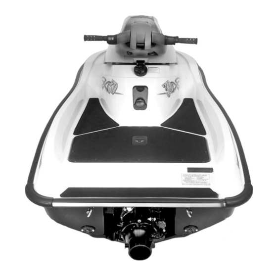
- Page 88 2004 3D RFI F22Z01S www.SeaDooManuals.net...
- Page 89 www.SeaDooManuals.net...
Need help?
Do you have a question about the 2004 3d rfi and is the answer not in the manual?
Questions and answers