Table of Contents
Advertisement
Service
This manual is to be used by qualified appliance
technicians only. Maytag does not assume any
responsibility for property damage or personal
injury for improper service procedures done by
an unqualified person.
Dual Fuel
Slide-In
Range
This Base Manual covers general information
Refer to individual Technical Sheet
for information on specific models
This manual includes, but is
not limited to the following:
JDS8850AAB/Q/S/W
JDS8850ACS/W
JDS9860AAB/P/W
JDS9860ACB/P/W
16026016
March 2005
©2005 Maytag Services
Advertisement
Table of Contents

Related Manuals for Jenn-Air JDS8850AAB


Summary of Contents for Jenn-Air JDS8850AAB
- Page 1 Refer to individual Technical Sheet injury for improper service procedures done by an unqualified person. for information on specific models This manual includes, but is not limited to the following: Dual Fuel JDS8850AAB/Q/S/W Slide-In JDS8850ACS/W JDS9860AAB/P/W JDS9860ACB/P/W Range 16026016 March 2005...
-
Page 2: Important Information
Important Information Pride and workmanship go into every product to provide our customers with quality products. It is possible, however, that during its lifetime a product may require service. Products should be serviced only by a qualified service technician who is familiar with the safety procedures required in the repair and who is equipped with the proper tools, parts, testing instruments and the appropriate service information. -
Page 3: Table Of Contents
Table of Contents Important Information ........... 2 Disassembly Procedures Important Safety Information Removing and Replacing Range ......24 All Appliances ............4 Cartridge Assembly (Select Models) ...... 24 Surface Cooking Units ..........5 Top Burner ............. 24 Safety Practices for Servicer ........5 Top Burner Lower Assembly ........ -
Page 4: Important Safety Information
Important Safety Information As with all appliances, there are certain rules to follow for WARNING safe operation. Verify everyone who operates oven is familiar with the operations and with these precautions. To reduce the risk of the appliance tipping, it must be secured by a properly installed anti-tip bracket(s). -
Page 5: Surface Cooking Units
Important Safety Information 5. User Servicing—Do not repair or replace any part of 1. Gas smell—Extinguish any and all open flames and the appliance unless specifically recommended in the open windows. manual. All other servicing should be referred to a 2. -
Page 6: Connecting Range To Gas
Important Safety Information Connecting Range to Gas cause burns, such as vent openings, window, oven door and oven racks. Install manual shut-off valve in gas line for easy • To avoid steam burns, do not use a wet sponge or cloth accessibility outside range. -
Page 7: Ventilation Hoods
VENTILATION HOODS Product Safety Devices 1. Clean Ventilation Hoods Frequently—Grease should Safety devices and features have been engineered into not be allowed to accumulate on hood or filter. the product to protect consumer and servicer. Safety devices must never be removed, bypassed, or altered in 2. -
Page 8: General Information
Brushed Chrome Amana Traditional White Magic Chef Traditional Almond Graffer & Prostyle Sattler Monochromatic Bisque Hardwick Stainless Jenn-Air Traditional Bisque Maytag W White on White Norge Frost White (True Color White) Universal Natural Bisque (True Color Bisque) Crosley Listing Fuel... -
Page 9: Specifications
Model Identification Complete enclosed registration card and promptly return. If registration card is missing: • For Jenn-Air product call 1-800-536 -6247 or visit the Web Site at www.jennair.com • For product inCanada call 1-866-587-2002 or visit the Web Site at www.jennair.com When contacting provide product information located on rating plate. -
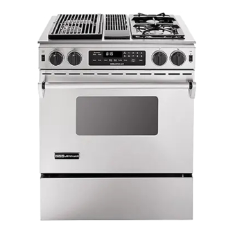
Page 10: Range Description
Range Description Range Description Downdraft Vent Top Surface Grill Module Burners and Grates Burner Control Valves Burner Control Valves Electronic Control Touchpad Oven Cavity Broil Element Bake Element Oven Light Convection Fan Bottom Access Pressure Regulator Panel (Back side of Range) Rating Label Model Number 16026016... -
Page 11: Troubleshooting Procedures
Troubleshooting Procedures W ARNING To avoid risk of electrical shock, personal injury, or death, disconnect power and gas to oven before servicing, unless testing requires power and/or gas. Troubleshooting Chart Problem Possible Cause Correction • Clean burner cap. Poor ground on burner cap ....... •... - Page 12 Troubleshooting Procedures W ARNING To avoid risk of electrical shock, personal injury, or death, disconnect power and gas to oven before servicing, unless testing requires power and/or gas. Problem Possible Cause Correction • Check element for continuity, replace No broil element operation Open broil element ........
-
Page 13: Fault Code Chart
Troubleshooting Procedures W ARNING To avoid risk of electrical shock, personal injury, or death, disconnect power and gas to oven before servicing, unless testing requires power and/or gas. Problem Possible Cause Correction • Allow cycle to complete. Oven is self-cleaning ....... •... - Page 14 Troubleshooting Procedures W ARNING To avoid risk of electrical shock, personal injury, or death, disconnect power and gas to oven before servicing, unless testing requires power and/or gas. Fault Code Description Component to Troubleshoot/Replace F1-A Lock/unlock switch state not advancing to control ......• Check connections, harness, and motor.
-
Page 15: Oven Sensor And Meat Probe Charts
Troubleshooting Procedures W ARNING To avoid risk of electrical shock, personal injury, or death, disconnect power and gas to oven before servicing, unless testing requires power and/or gas. Oven Sensor and Meat Probe Charts OVEN SENSOR Sensor Type: RTD 1000Ω platinum Calibration: 1654Ω... -
Page 16: Testing Procedures
Testing Procedures WARNING To avoid risk of electrical shock, personal injury or death; disconnect power to oven before servicing, unless testing requires power. Component Testing Procedures Illustration Component Test Procedure Results Oven light housing Disconnect connector and test Verify bulb is plugged in properly. All models resistance of terminals...... - Page 17 Testing Procedures WARNING To avoid risk of electrical shock, personal injury or death; disconnect power and gas to oven before servicing, unless testing requires power and/or gas. Illustration Component Test Procedure Results Top surface burner Verify gas is supplied ......Check for obstructions in burner ports.
- Page 18 Testing Procedures WARNING To avoid risk of electrical shock, personal injury or death; disconnect power and gas to oven before servicing, unless testing requires power and/or gas. Illustration Component Test Procedure Results Venturi, rear Nominal air shutter setting....375 3/8" (long) Tolerance ...........
-
Page 19: Oven Control Testing Procedures
Testing Procedures WARNING To avoid risk of electrical shock, personal injury or death; disconnect power and gas to oven before servicing, unless testing requires power and/or gas. WARNING To avoid risk of electrical shock, personal injury or equipment failure, use extreme caution when taking voltage measurements in the Electronic Control. - Page 20 Testing Procedures WARNING To avoid risk of electrical shock, personal injury or death; disconnect power and gas to oven before servicing, unless testing requires power and/or gas. Component Test Procedure Results Trace Measurement Control Panel Assembly Closed circuitry resistance (defined as continuity): 7 &...
-
Page 21: Relay Logic
Testing Procedures WARNING To avoid risk of electrical shock, personal injury or death; disconnect power and gas to oven before servicing, unless testing requires power and/or gas. Relay Logic NOTE: Subsequent changes implemented after the release of this technical sheet may have altered the parameters identified in this chart. -
Page 22: Quick Test Mode
Testing Procedures WARNING To avoid risk of electrical shock, personal injury or death; disconnect power and gas to oven before servicing, unless testing requires power and/or gas. "Quick Test" Mode for Electronic Oven Control (EOC) II Follow the procedure below to perform the EOC II quick test. Instructions must be entered within 16 seconds of each other (via the touch pad) or the EOC will exit the test mode. -
Page 23: Description Of Fault Codes
Testing Procedures WARNING To avoid risk of electrical shock, personal injury or death; disconnect power and gas to oven before servicing, unless testing requires power and/or gas. Description of Fault Codes Each Fault Code consists of an "F" followed by a number, dash and a number or letter. The following table describes each Fault Code and the component to troubleshoot. -
Page 24: Disassembly Procedures
Disassembly Procedures To avoid risk of electrical shock, personal injury or death; disconnect power to unit before servicing. Removing and Replacing Range Top Burner Lower Assembly 1. Remove power from unit. 1. Remove maintop, see "Maintop Removal" procedure. (Perform steps 1 – 7.) 2. -
Page 25: Maintop Assembly
Disassembly Procedures To avoid risk of electrical shock, personal injury or death; disconnect power to unit before servicing. Maintop Assembly 1. Remove power from unit. 2. Remove range from installation position, see “Removing and Replacing Range” procedure. 3. Remove air grill, filter, grill grates, aeration pan and Electronic cartridges (select models). -
Page 26: Meat Probe Receptacle (Select Models)
Disassembly Procedures To avoid risk of electrical shock, personal injury or death; disconnect power to unit before servicing. Downdraft Blower Motor (Select Models) Meat Probe Receptacle (Select Models) 1. Remove power from unit. 1. Turn power off. 2. Remove bottom access panel, see "Bottom Access 2. -
Page 27: Oven Light Switch
Disassembly Procedures To avoid risk of electrical shock, personal injury or death; disconnect power to unit before servicing. 1. Remove power from unit. 5. Label and disconnect electrical connection. 2. Open oven door and locate oven light. 6. Replace and reverse procedure to reinstall motor. 3. -
Page 28: Oven Door Removal
Disassembly Procedures To avoid risk of electrical shock, personal injury or death; disconnect power to unit before servicing. 2. Place door on a protected surface. Oven Door Removal 3. Remove screws securing bottom trim to oven door. 4. Slide outer oven door glass and trim towards the WARNING bottom of the oven door and remove. - Page 29 Appendix A 16026016 A – 1 ©2005 Maytag Services...
-
Page 30: Appendix A: Installation Instructions
Installation Instructions (Model JDS8850A**) INSTALLATION DRAWINGS IMPORTANT PLEASE KEEP FOR THE USE OF THE LOCAL ELECTRICAL INSPECTOR. FIGURE 1 NOTE: Figure may not be representative of actual unit. The 30 inches (76.2 cm) minimum clearance between the installing a range hood that projects horizontally a top of the cooking surface and the bottom of an minimum of 5 inches (13 cm) beyond the bottom of the unprotected wood or metal cabinet can be reduced to 24... -
Page 31: Model Jds8850A
Installation Instructions (Model JDS8850A**) FIGURE 2 FIGURE 3 NOTES: 1. Provide for either a 3-wire or 4-wire 120/208, 120/240 volt outlet per applicable cord in shaded area shown. Refer to installation instructions for proper positioning of outlet. This is also the recommended gas line location. 2. - Page 32 Installation Instructions (Model JDS8850A**) WARNING THIS PRODUCT SHOULD NOT BE INSTALLED BELOW A VENTILATION TYPE HOOD SYSTEM THAT DIRECTS AIR IN A DOWNWARD DIRECTION. (SEE FIGURE) THESE SYSTEMS MAY CAUSE IGNITION AND COMBUSTION PROBLEMS WITH THE GAS BURNERS RESULTING IN PERSONAL INJURY AND MAY AFFECT THE COOKING PERFORMANCE OF THE UNIT .
- Page 33 Options STEP 3 - Range Installation A. Wood Construction: A. A Jenn-Air range may be installed by one person. 1. Floor: Locate the center of the two holes identified B. Align the range to its designated location and slide it in figure 5 as “HOLES FOR FLOOR.”...
- Page 34 Installation Instructions (Model JDS8850A**) CONNECTING THE RANGE TO ELECTRIC SUPPLY RANGE CONNECTIONS WARNING Some models are shipped direct from the factory with service cords (pigtails) attached. There are no range DISCONNECT ELECTRICAL SUPPLY connections necessary on these models. Just plug into the range outlet.
- Page 35 Installation Instructions (Model JDS8850A**) FIGURE 8 FIGURE 9 3-Wire Service Cord or Conduit Installation 4-Wire Service Cord or Conduit Installation 1. Insure that the copper ground strap IS CONNECTED (Mobile Homes Or As Required By Codes) between the middle post of the main terminal 1.
- Page 36 Installation Instructions (Model JDS8850A**) CONNECTING THE RANGE TO GAS SUPPLY GAS SUPPLY Installation of this range must conform with local gas valves or controls and clog burners and/or pilot orifices. codes or, in the absence of local codes, with the National Fuel Gas Code, ANSI Z223.1-latest edition.
-
Page 37: Model Jds9860A
Installation Instructions (Model JDS9860A**) FIGURE 1 FIGURE 2 NOTES: 1. Provide for either a 3-wire or 4-wire 120/208, 120/240 volt outlet per applicable cord in shaded area shown. Refer to installation instructions for proper positioning of outlet. This is also the recommended gas line location. 2. - Page 38 STEP 2 - Anti-Tip Bracket Installation pan of water on the cooktop or the oven rack. A. Wood Construction: Jenn-Air ranges require total removal from cabinet 1. Floor: Locate the center of the two holes identified before an adjustment can be made.
- Page 39 Installation Instructions (Model JDS9860A**) CONNECTING THE RANGE ELECTRIC SUPPLY RANGE CONNECTIONS The range must be installed in accordance with Local and Some models are shipped direct from the factory with National Electric Code (NEC) ANSI/NFPA No. 70-latest service cords (pigtails) attached. There are no range edition.
- Page 40 Installation Instructions (Model JDS9860A**) 3-WIRE SERVICE CORD OR CONDUIT 4-WIRE SERVICE CORD OR CONDUIT INSTALLATION INSTALLATION (MOBILE HOMES OR AS REQUIRED BY CODES) 1. Insure that the copper ground strap IS CONNECTED between the middle post of the main terminal 1.
- Page 41 Installation Instructions (Model JDS9860A**) DOWNDRAFT INSTALLATION INSTRUCTIONS S Determine where you will be locating the electrical outlet. It must be in the floor or on the wall within the area shown in figure 2 or 3. S Determine how you will be venting your downdraft blower.
- Page 42 Installation Instructions (Model JDS9860A**) 3. Make cutout in the cabinet floor of either the right or left side cabinet as shown in figures 14 or 15. 4. Relocate the mounting brackets on the blower housing as shown in figure 17. NOTE: The mounting br ackets shown in figure 16 are as assembled at the factory for floor or...
-
Page 43: Range Installation
Installation Instructions (Model JDS9860A**) 8. Install the 6 (15.24 cm) elbow of the blower housing INSTALLING THE BLOWER and secure with duct tape. The open end of the elbow NOTE: Install the blower prior to installing the should be pointed to the left. Attach the 6 (15.24 cm) range. - Page 44 Installation Instructions (Model JDS9860A**) CONNECTING APPLIANCE TO GAS SUPPLY A QUALIFIED SERVICEMAN OR GAS APPLIANCE INSTALLER MUST MAKE THE GAS SUPPLY CONNECTION. Leak testing of the appliance shall be conducted by the installer according to the instructions given. INSTALL GAS SHUTOFF VALVE Install a manual shutoff valve in an accessible location in the gas line external to this appliance for the purpose of turning on or shutting off gas to the appliance.
- Page 45 Appendix B 16026016 B – 1 ©2005 Maytag Services...
-
Page 46: Appendix B: Use Information
Use Information (Model JDS8850A**) OOKING IMER ONTROL PTIONS ETTING ONTROL UNCTIONS ONTROL PERATION LOCK B – 2 16026016 ©2005 Maytag Services... - Page 47 Use Information (Model JDS8850A**) OOKING CONT NOTES: ANCEL ONVECT ONVECT OAST SELECT MODELS 16026016 B – 3 ©2005 Maytag Services...
- Page 48 Use Information (Model JDS8850A**) ROIL UICK REHEAT SELECT MODELS LOCK ONTROLLED OOKING NOTES: B – 4 16026016 ©2005 Maytag Services...
- Page 49 Use Information (Model JDS8850A**) OOKING CONT SELECT READ ROOFING MODELS SELECT MODELS NOTES: MEAT P ROBE SELECT MODELS 16026016 B – 5 ©2005 Maytag Services...
- Page 50 Use Information (Model JDS8850A**) OOKING CONT 12 H ABBATH EFAULT ONTROL PTIONS ISPLAY LOCK OUND EVEL EMPERATURE DJUSTMENT 12/24 H LOCK PTIONS VAILABLE CROLL PEED - -T ND OF IMER IGNAL 1 & T IMER IMER - -C ND OF IGNAL ONTROL C/F (7)
- Page 51 Use Information (Model JDS9860A**) OOKING ONTROL ETTING ONTROL PERATION UNCTIONS LOCK IMER ONTROL PTIONS 16026016 B – 7 ©2005 Maytag Services...
- Page 52 Use Information (Model JDS9860A**) OOKING CONT ANCEL ONVECT ROIL ONVECT OAST NOTES: B – 8 16026016 ©2005 Maytag Services...
- Page 53 Use Information (Model JDS9860A**) UICK REHEAT LOCK ONTROLLED OOKING NOTES: 16026016 B – 9 ©2005 Maytag Services...
- Page 54 Use Information (Model JDS9860A**) OOKING CONT READ ROOFING NOTES: Meat P ROBE B – 10 16026016 ©2005 Maytag Services...
- Page 55 Use Information (Model JDS9860A**) OOKING CONT OUND EVEL ISPLAY LOCK ONTROL PTIONS EMPERATURE 12/24 H LOCK DJUSTMENT CROLL PEED PTIONS VAILABLE End-of-Timer S IGNAL - -C ND OF IMER IMER IGNAL C/F (7) ONTROL IGHT ANGUAGE 12 H ABBATH EFAULT 16026016 B –...
- Page 56 Care Information & C LEANING LEAN NOTES: B – 12 16026016 ©2005 Maytag Services...
-
Page 57: Care Information
Care Information & C LEANING CONT LEANING ROCEDURES – P LOCK AND ONTROL ANDLE LASTIC INISHES ONTROL ANEL CCESS ANEL & D – INDOW LASS ONTROL NOBS PRONGS PRONGS GREASE NTERIORS & S EALED URNER ARTRIDGE ORCELAIN NAMEL ACKS ROILER AN AND NSERT 16026016... - Page 58 Care Information EALED URNER SSEMBLY – RILL SSEMBLY – P ASIN ORCELAIN RILL URNER TAINLESS TEEL SELECT MODELS REASE – C AST ALUMINUM COATED WITH NON STICK FINISH B – 14 16026016 ©2005 Maytag Services...
- Page 59 Appendix C 16026016 C – 1 ©2005 Maytag Services...
-
Page 60: Lp Conversion Instructions
LP Conversion Instructions GAS CONVERSION General Appliance Pressure Regulator Conversion All ranges and cooktops are equipped with double coaxial The unit appliance pressure regulator must be set to (universal) orifices and with a convertible appliance match the type gas supply used. If converting from natural pressure regulator. - Page 61 LP Conversion Instructions ORIFICE CONVERSION 1. From Natural Gas To LP/Propane Gas: FOR ALL TOP BURNER AND a. Change the appliance pressure regulator from OVEN SAFETY VALVE CONVERSION natural to LP setting. (See figures 10, 11 or 12). (EXCEPT EATON VALVE) b.
- Page 62 LP Conversion Instructions SURFACE BURNER HEADS HOW TO REMOVE RANGE BURNER BASES CLEANING AND SERVICING Follow these procedures to remove appliance for The surface burner heads are removable. The cap cleaning or servicing: portion of the head is porcelain and the port area is aluminum.
Need help?
Do you have a question about the JDS8850AAB and is the answer not in the manual?
Questions and answers
We just had an electrical storm and momentary power outage. The panel no longer is lit showing time, etc, but the light inside the oven and the burner ignitors function.
The issue with the Jenn-Air JDS8850AAB oven panel not lighting after a power outage could be a bad clock/display board. This is often caused by failed power capacitors on the board. Replacing the board or repairing it at the component level may resolve the problem.
This answer is automatically generated
I am desperately trying to find a control panel for a model JDS9860AAP dual fuel downdraft JennAir 30" slide-in oven/range. We love the unit, but at this time, buying a new unit is beyond our means.