
Related Manuals for Alto MAXIDRIVE3.4


Summary of Contents for Alto MAXIDRIVE3.4
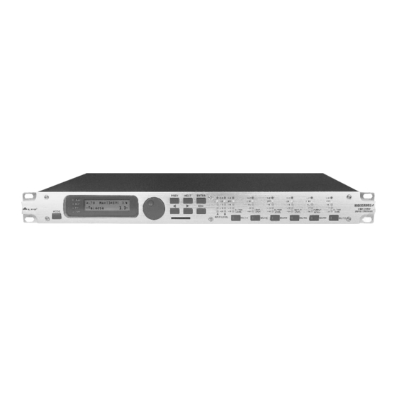
- Page 1 User's Manual 3 WAY STEREO ¡V MAXIDRIVE3.4 DIGITAL CROSSOVER www.altoproaudio.com Version 2.0 September 2003...
- Page 2 the recommendedfusetypeas indicatedinthismanual. SAFETY RELATED SYMBOLS Donotshort-circuitthefuseholder.Beforereplacingthe fuse,makesure thattheproductis OFFanddisconnected CAUTION fromthe ACoutlet. RISKOFELECTRICSHOCK DONOTOPEN £» ProtectiveGround Before turning theproductON, make sure that it is This symbol, whereverused, alertsyoutothe pre- sence ofun-insulatedanddangerous voltageswith- connectedto Ground.Thisis topreventtheriskof intheproductenclosure.Thesearevoltagesthat electric shock. maybesufficient toconstitute the risk of electric Never cut internal orexternal Ground wires.Likewise, shock ordeath.
- Page 3 PREFACE DearCustomer: ThanksforchoosingM AXIDRIVE3.43 - WayStereoDigitalCrossoverandthanksforchoosingone oftheresultsof ¡¶ LTOAUDIO TEAM jobandresearches. Forour ¡¶ LTO AUDIO TEAM, musicandsoundaremorethanajob...arefirstofallpassionand letussayourobsession! Wehavebeendesigningprofessionalaudio products fora long time incooperationwith someof themajorbrands in theworldintheaudiofield. ¡¶ LTOlinepresents unparalleled analogueanddigitalproductsmade by MusiciansforMusicians inourR&D centersinItaly,Netherlands, UnitedKingdomandTaiwan.Thecoreof our digitalaudioproductsisasophisticated DSP(DigitalSoundProcessor)andalargerangeof stateoftheartalgorithmswhich have eendeveloped byour Software Team for the last7 years.
-
Page 4: Table Of Contents
TABLE OFCONTENTS 1. INTRODUCTION ........................... 4 2.FEATURES .............................4 3.CONTROLELEMENTS .........................4 3.1TheFrontPanel 3.2TheRearPanel 4. GETTINGSTARTED ..........................4.1Configurationof TheSystem 4.2AdjustThe Input Signal 4.3FirstSetup 4.4SystemConfiguration 4.5Numberof Presets 4.6Type ofPreset 4.7NameofThePreset 4.8PresetModifications 4.9SystemProtection THEMENUMAPCONFIGURATIONDESCRIPTION ................. 5.1PresetMenu 5.2DelayMenu 5.3Edit Menu 5.4UtilityMenu 6. CONNECTIONS ............ -
Page 5: Introduction
1. INTRODUCTION YourMAXIDRIVE3.4 isa3-way stereodigitalcrossoveranditisapowerfulversatilesignalprocessor. Theapparatus willprovide 3,4,5or6-waymonoX-overwith6 outputs.Thanks totheuseofselectedandexpensivecomponents, theperformancesofMAXIDRIVE3.4areworthmuchmorethan itsprice:youcanset the inputandoutput routingcon- figurationonly throughrecallingoneofthe Presetsincludedin theinternalmemory. 2. FEATURES Singlerack unit £» Delay lines upto2.5sfor eachinputandupto 300msforeachoutput £» Stereodigitalinput inAEX/EBU format £» A/DandD/Aconvertersfora117dBdynamicrange £» Slotforamemory cardforthestorage ofmore presetsand aneasierupgradeofother units £»... -
Page 6: Therearpanel
7.Memory Card Slot TheSlotallowsyoutoinserttheMemoryCardwhichisvery usefulforsafestorageofPRESETS andfor their transferfrom one MAXIDRIVE3.4to another. 8.ENTERkey Thekeyallowsyoutoaccesstotheselectedediting page ressingthis key,y oucaneditandconfirm therequired value ofparameter. 9.ESCkey The key allowsyouto exittheselectedediting page.It also used torejectthe valueto enter and returnto the stored value. 10.InputLevelLEDs TheLEDsareusedtoindicatethelevelofinputA/B.Inordertogetanup-front distortion-freesignal, y o u k e e p thesignalquitehigh,butdoassurethatthe redCLIP LED doesn'tlightup continually. -
Page 7: Gettingstarted
DRIVE3.4andPCorotherMAXIDRIVE3.4units.TheRS485interfaceisvery suitablefor remote controlover longdistances (difficultwithRS232 standardports)and daisy-chaining severalMAXIDRIVE3.4. 17.RS485IN The function oftheRS485INport isoppositetoRS485OUT.Itallows incoming communication b e t w e e n a MAXIDRIVE3.4 andPCorotherMAXIDRIVE3.4 units. The R S485 interfaceisverysuitableforremotecontrol overlong distances(Difficult with RS232standard ports) andfordaisy-chainingseveralMAXIDRIVE3.4. 18.RS 232 Thisistheserialcommunicationinterfaceport.ItallowsincomingandoutgoingcommunicationbetweenaMAXI- DRIVE3.4and a PCorother MAXIDRIVE3.4units. -
Page 8: Adjustthe Input Signal
Proceedasfollows: £»Keep theMAXIDRIVE3.4outputsin MUTE status(LEDslighton). £» Feed a signal inonthe MAXIDRIVE3.4's inputand watchthe INPUT LEVELA-B LEDladders. To obtainagoodsignal/noise ratio,i.e. anup-frontdistortion-freesignal,keepthesignalquite high,but make certain the red CLIP LEDdoesn'tlightup continually. £» Find out the output levelsettingfor yourmixer(or otherunit)and connect it tothe inputoftheMAXIDRIVE3.4. -
Page 9: Firstsetup
G A I N G A I N I N A I N A & B . 0 d B . 0 d B Usethe DIAL tochangethegainvalueandwatchthelevel ofthesignalontheLEDladdersuntiltheidealvalues arereached. I N A G A I N I N A & B G A I N . -
Page 10: Numberofpresets
Numbers 1 , 2 , 3 , 4 , 5 indicate therespective outputs. Intheexample: Thesignal connectedtoInput isassignedto outputs and . Thesignal connectedtoInput isassigned tooutputs and . ofthesignaloninputs is assigned tooutputs and . Thesystemisthereforeconfiguredasshowninthefollowingdiagram. A13B24S56 2-WAYSTEREO+2MONOAUX(2X2W+2MAX) LEFT HIGHLEFT HIGHRIGHT LOWLEFT LOWRIGHT MONOAUXL+R MONOAUXL+R RIGHT... -
Page 11: Presetmodifications
4.8PRESETModifications A 1 3 B 2 4 S 5 6 2 x 2 W + 2 M A X Thisindicatesthatthevalueofoneormoreparametershasbeentemporarilymodifiedwithrespecttothe stored inthePRESETshown. Practicallyspeaking,thisindicationmeansthatthechangesmadetothePRESET havenotbeenstored. Note: onceithasbeenenabled,theindicationremainsevenifthe"original"valuesareresetmanually. TheindicationdisappearsassoonasthePRESETissavedorassoonasanewPRESETisloaded(includ- ingthissamePRESET). Inotherwords,theindicationdisappearsassoonasstoredvaluesareaccessed. IfthePRESETisn'tsaved,temporarychangesarelostassoonasanewPRESETis loaded(includingthis same PRESET). Note: temporary changesarekeptontheotherhandinthe"buffermemory":whentheunitisswitchedon,the system maintainsexactlythesamesettingsaswhentheunitwasswitchedoff,includingtemporarychanges. 4.9.System Protection A 1 3 B 2 4 S 5 6... - Page 12 Thereare3distinctcategoriesofPRESETS: Factory PRESETS Factory-programmedstorage. FactoryPRESETScanbeusednormally,temporarilymodified,butcan't becancelled, overwrittenorpermanently modified.FactoryPRESETScontainsomespecific s ettings forcertain typesofenclosuresandallthe system'susableconfigurations.Forthis reasonthey'retheideal starting point forcreatingcustom PRESETS. User PRESETS Storeddatathat canbe programmed byusers. UserPRESETSareinternalmemoryareas inwhichyourownpersonal settings can be saved. Card PRESETS StoreddatawhichcanbeprogrammedbyusersonaMultimedia MemoryCard. CardPRESETSareexternalmemoryareasinwhichyourownpersonal settingscan be saved. 5.1.1 LoadPRESET Thismenupageallows therequired PRESETtobeloadedandmadeoperatively.
- Page 13 Note: In theexample, FactoryPRESET#3 ,named"2x3W"hasbeenloaded:ItssystemconfigurationisInputA signalassigned tooutputs1,3and5;InputBsignalassignedtooutputs2,4 and6. LoadingaPRESET,aPRESETChangecommandisalsoautomaticallysenttotheserial portsandcanbeused toautomaticallyloadaPRESETwiththesamenumbertoanyotherMAXIDRIVE3.4unitsconnectedandenabled (Refer to UTILITY menu -Comm. Setup submenu -PRESET ChangeRX option). 5.1.2 Store&NamingPRESET Use this menu tocreatenewPRESETS, i.e. to saveallthe currentsystem settings. S t o r e P r e s e t + 2 M A X 2 x 2 W TosaveaPRESET:...
- Page 14 Note: Inorderforthe transfer tohaveeffect,thereceivingunitsmustbeabletoidentify and acceptIncoming Dumpoperations. Whentwo o r m o r e MAXIDRIVE3.4 areconnected,the PRESETsentbythe transmitting MAXIDRIVE3.4 (TX) overwrites(andthereforecancels)theexistingPRESETin the s ame memory position ofthereceivingMAXI- DRIVE3.4 (RX). MAXIDRIVE3.4 # 1 MAXIDRIVE3.4 # 2 MAXIDRIVE3.4 # 3 IncomingDump IncomingDump IncomingDump DUMP ACCEPT DUMP...
-
Page 15: Delaymenu
Ignorethe datareceived via the serial ports. Accept the datareceived via the serialports. I n c o m i n g D u m p I n c o m i n g D u m p n o r e c e p t 5.2.DelayMenu Usethismenuto workon thesystems delaylines. - Page 16 OutputDelay onlydelaysthesignalofaspecificoutput. Also called ChannelDelay,outputdelay ismainlyused tocompensateforthe distance between differentblocksofthesamesoundsystem(forexample clusters)ortocorrect internalalignmentofaspeakerenclosurecomponents. 5.2.1InputDelay Usethismenu page toadjustthedelaylinesofInputA,Input B and SUM. I n p u t D e l a y I N A Thevaluescanbesetinthefollowingranges: INPUTDELAY I N A D E L A Y 7 7 m S step unit...
-
Page 17: Edit Menu
Thevaluescanbesetinthefollowingranges: OUTPUTDELAY 0 P 1 D E L A Y 2 9 2 u S u n i t range step 0 . 0 ~ 1 0 0 . 0 0 ~ 100000 0 ~ 2 9 1 0 ~ 2 9 1 2 7 1 Thevaluescanbesetinthefollowingranges: OUTPUTDELAY OUTPUT DELAY... - Page 18 I n p u t G a i n Allowstoadjusttheamplificationof the signalfedinthroughInputsAandB. Editingvalues areintherange +6dB~-30dB, with0.5dBsteps. I N A G A I N - 2 . 5 d B Note: Setting the inputsignalofadigitalunitisparticularlyimportant,much morethanonananalogunit,as any saturationoftheA/D converterduetoanexcessivelyhigh inputsignalcausesatypicalparticularlydistinct noise.To achieveagoodsignal/noiseratio,i.e.anup-front distortionfreesignal,feed a signalinonthe MAXI- DRIVE3.4'sinput andwatchthe INPUT LEVELA-B LEDladders.Keepthe signal quiteh...
- Page 19 b. Centre Frequency / C utoff Frequency Allows tochoosethecentrefrequency ofthePeaking curveandNotchfilter,orthe cutofffrequencyofShelv- ing curves. I N A E Q 1 1 . 0 - 5 . 0 Notch Peaking LowShelving HighShelving c. Bandwidth AllowstochoosethewidthinoctavesofthePeakingorNotchtypecurve.ItsnotusedwithShelving curves. I N A E Q 1 1 .
- Page 20 The valuescanbesetinthefollowingranges: 5.3.3Xover Low-passandhigh-passfilters. Madeupofacombinationofalow-passfilterandhigh-passfilter,thecrossoverallowstodivide the audiosignal into segments thatcanbeused bytheindividualsectionofasoundsystem(forexample High, Mid&Low). X o v e r EachXoverhas2slightlydifferentpages(oneforeachfilter),wherethename oftheoutput itaffects and the typeoffilterareshown. L P F h r u H P F h r u O P 1 1 k 0 0 H z 1 k 0 0 H z O u t p u t 1 - L o w P a s s F i l t e r O u t p u t 1 - H i g h P a s s F i l t e r...
- Page 21 Each filterhasthefollowing editableparameters: Typeoffilter Allowstochoosethreedifferenttypes o f filter anddifferentattenuationslopes: Butterworth (But)at6,12, 18 or24dBper octave, Bessel (Bes)at12, 18or24dBper octave, Linkwitz-Riley (LR)a12,24or48dBperoctave. Bysettingthe Thru value,thefilterisdisabledandthesignal passeswithoutitsfrequency being al tered. L P F O P 1 B e s 2 k 0 0 Crossover frequency Allowstochoosethefiltercutoff frequency.
- Page 22 5.3.4OutputEQ Output equalizer with 5 parametric filters. AlsocalledChannelEQ,allowstoalterthe tone o f eachindividualoutput. Thecharacteristics ofqualityandprogrammabilityareidenticaltothoseoftheInputEqualizerand enablethis unit to b e usedextremelyeffectivelyand flexibly. O u t p u t Eachequalizer has5pages(one perfilter),indicatingthenameoftheoutputiteffectsandthenumber ofthefilter. E Q 1 e a k O P 1 1 .
- Page 23 Reverse:shiftsthephasethrough180 , invertingit. Normal:leavesthephaseunchanged ¢X O P 1 P O L A R I T Y O P 1 P O L A R I T Y N o r m e v e r Theeffectofthiscontrolissummedwiththatofthe £X parameterofthe filter( Xover-EDIT menu),which operateswith5 steps inarangeofbetween0 and180.
-
Page 24: Utilitymenu
IMPORTANT! Enabling theLIMITER ona specificoutput alsochangestheway inwhichthelevel isdisplayed onthecorresponding LED ladder: In fact,thelevelshown onthisladderisnolongerthe"absolute"outputlevel, but thelevelof thesignalat-24dB,-12dB,-6dB comparedtothe LIMITER's threshold (orange LIMIT LED),no matterwhat thethreshold valueis. 5.4UTILITY Menu Thismenucomprisesaseriesofsubmenusthatallowtosetaseriesofsystemoptionsandaccesscertainutilities, such asthe control ofthe MultimediaMemory CARD orprotection againstaccidentalorunauthorizedchanges: menu Ganging InputGanging UTILITY OutputGanging Units... - Page 25 G a n g i n g ThepracticaluseoftheGangingfunctionconsistsin thepossibility ofeditingwithidenticalvaluestheparameters ofsimilarelements, carryingoutsingle(instead ofdouble)operations. For example,it's possible to setthesameDelayvalueor equalization onboth inputswithjustone operation; orsetidenticalXover parametersforthevariousoutputsfedtoa stereosoundsystem;oryetagain,enable the LIMITERsimultaneouslyon thetwooutputsdedicated to two mono stagemonitors. Thesystemautomatically recognizesincompatibleelementscontainedinthevariousconfigurationsandonly enables theGanging function whereit can effectivelybeused.Therefore,the Gangingfunctiondoesn'thave any effectontheMONOsetups.TheGangingfunctioncanbeenabled separatelyfor bothgroupsof inputand groups ofoutputs.
- Page 26 b.OutputGanging Usedtoenable/disableGangingfunction ontheoutputs. Thesettingsare: Disabled Enabled O u t p u t G a n g i n g O u t p u t G a n g i n g O f f 5.4.2 UNITS SUBMENU Units DelayUnit L i m .
- Page 27 5.4.3 Misc. Setupsubmenu Misc.Setup InputSelect OutputMeters Temperature WakeUp LCDContrast Usethissubmenutosetaseriesofsystemoptions. M i s c . S e t u p a.InputSelect Used tochoose inputs whichMAXIDRIVE3.4 shoulduse. Theoptions include: DigitalInputs AnalogInputs I n p u t S e l e c t I n p u t S e l e c t i g i t a l...
- Page 28 c.Temperature Usedtokeyin thevalueoftheenvironmentaltemperatureof place ofinstallation. The systemuses thisvalue toautomaticallycompensate for thedifferentialsdueto the difference speedof soundTransmission accordingtothe airtemperature. This allowstosetthedelaysduringthe sound-checkandonlyhavetoresetthemautomaticallywhennecessary (Forexampleduring a concert, i n t h e event ofbig jumpsintemperature, etc.). The editingvaluesareinthefollowing ranges: +60 C ~ -30 C ¢...
- Page 29 L o c k Thisfunctionisveryusefulwhenevereventemporarychangesortampering withthesettingsstoredinthesystem must beprevented.For example:fixedinstallationsusedbyseveraloperators(discotheques, clubs,conference halls,etc.),soundsystemrental,etc. Howtoenable protection £»Firstof all, choosetheprotectionmode: Twomodesareavailable: Total: Partial: all editingfunctions areblockedand only theparameters relativetotheInputs accesstothePRESETmenuis disabled canbeedited(Delay, Gain,EQ), allothereditingfunctionsareblocked andaccesstothePRESET menu disabled L O C K T o t a l L O C K P a s s w o r d P a s s w o r d...
- Page 30 A 1 3 B 2 4 S 5 6 2 ¡Ñ 2 W + 2 M A X Note: alongside thesymbol ofTotal orPartialprotection,theletter mayalsoappear.Thismeansthatthesystem isprotected, but the PRESET in question has undergoneone ormorechanges that havenotyetbeen stored.Youcanhowever switchthesystemonandoffwithoutanyproblems,as thecurrentsettingsare keptin thebuffermemory.Nevertheless,ifthisisyourwork setup, it'sadvisableto store itinaPRESET. To unlockthe protection: £»...
- Page 31 ATTENTION! Formatting cancelsany datacontainedintheCard. IntheMemoryCardsubmenu, press ENTER. F o r TheFormatCardpageappears PressENTER. £» The system formatsthe Carduntilitcommunicates that it h ascompleted. Thisoperationonlyrequiresafewseconds. TheCardisreadytobeused. F o r F o r F o r t i n g . . . F o r D o n e Note: intheevent of an error or a Card fault, ifthereisnoCardintheslotoriftheCardisremovedduring formatting,thedisplayshowsthefollowing message:...
-
Page 32: Connections
The PRESETChange command iscompletely identicaltoMIDIProgramChange:thetransmittingunitsends aninstructioncontaininga number o f PRESETStoload; thereceivingunits (iftheyareabletoacceptthe com- mand)each loads intoitsownmemorythePRESETwiththecorrespondingnumber. Thismeansthat,ina chainofMAXIDRIVE3.4,alltheunitssetwithPRESETChangeRX=Acceptloadthesame number ofPRESET, inspiteofthefactthatitcorrespondstoPRESETS withdifferentcontentsinthevarious units. Note: thePRESET Dump functionisusedtotransmitthesamecontents. MAXIDRIVE3.4 # 1 MAXIDRIVE3.4 # 2 MAXIDRIVE3.4 # 3 LoadPreset PresetChangeRX PresetChangeRX ACCEPT... -
Page 33: Application
Outputs1~ 6,RS485OUT HOT(+) BALANCEDXLR-F GROUND COLD( ) ¡V RS232 RS232(9-Pin) 7.APPLICATION Thefollowing diagramsshowtheMAXIDRIVE3.4'svarioussystemconfigurations,asiftosay,thevarious inputand outputhardwarecombinations. 7.1.FactoryPresetConfiguration Name Configuration Configuration DEFAULT A135B246 Defaultpreset-routing=3-WAYSTEREO 2X2W+MAX A13 B24S56 2-WAYSTEREO+2MONOFULL-RANGEOUT 2X3W A135B246 3-WAYSTEREO 2X3W+MSB+MAX A13 B24S56 3-WAYSTEREO withMONOSUB+1MONOFULL-RANGEOUT 4W+2MAX A1324S56 4-WAYMONO+2MONOFULL-RANGEOUT 4W+BSB+2MAX A123B4S56 4-WAYMONOwithB-SUB+2MONOFULL-RANGEOUT 5W+MAX A12345S6 5-WAYMONO+1MONOFULL-RANGEOUT... -
Page 34: Organization
PUSH OUTPUTS tillettnatverk FUSE:95-120VT500mAL 210-240VT315mAL N E W TIDE N E W T I D E N E W TIDE TIDE A102 INPUTB INPUTA DIGITALIN RS485OUT R S 4 8 5 I N RS232 MAXIDRIVE3.4 3-WAYSTEREO DIGITALCROSSOVER AUDIOMIXER SIGNAL POWER... - Page 35 T I D E N E W TIDE T I D E A102 DIGITALIN R S 4 8 5 O U T R S 4 8 5 I N RS232 INPUTB I N P U T A MAXIDRIVE3.4 3-WAYSTEREO DIGITALCROSSOVER AUDIOMIXER SIGNAL POWER...
- Page 36 T I D E N E W T I D E A102 O F F DIGITALIN RS485OUT RS485IN R S 2 3 2 I N P U T B I N P U T A MAXIDRIVE3.4 3-WAYSTEREO DIGITALCROSSOVER AUDIOMIXER SIGNAL POWER...
- Page 37 N E W T I D E TIDE TIDE A 1 0 2 DIGITALIN R S 4 8 5 O U T RS485IN R S 2 3 2 I N P U T B I N P U T A MAXIDRIVE3.4 3-WAYSTEREO DIGITALCROSSOVER SIGNAL POWER AUDIOMIXER...
- Page 38 / from RS232SerialPort MAXIDRIVE3.4 3-WAYSTEREO t o / f r o m DIGITALCROSSOVER RS232 ACINPUT 1 4 W Apparatenskallanslutastill P U S H PUSH jordatuttagnardenansluts 95-240V50/60Hz PUSH PUSH OUTPUTS tillettnatverk FUSE:95-120VT500mAL 210-240VT315mAL N E W TIDE N E W TIDE...
-
Page 39: Technicalspecifications
8.TECHNICALSPECIFICATIONS INPUT section Connectors 2 x COMBO Nominal inputsensitivity 0 dB(0.775V) Input Impedance 30kOhm, electronically balanced Maximum InputLevel +20dBu Input Gain -30 / +6dBvariablein0.5dB steps Digital input AES/EBU, XLR-F Digital input samplerate 32 kHz~48kHz OutputSection Connectors 6 x XLR-M Output Impedance 600 Ohms,electronicallybalanced Nominal OutputLevel 0 dBu... -
Page 40: Warranty
9 . WARRANTY 1. WARRANTY REGISTRATIONCARD ToobtainWarrantyService, thebuyer shouldfirstfilloutandreturntheenclosedWarrantyRegistrationCard within 10daysofthe PurchaseDate. Alltheinformationpresentedin thisWarranty R egistration Cardgivesthemanufacturerabetterunderstanding of thesalesstatus,soastopurportamoreeffectiveandefficientafter-saleswarrantyservice. Pleasefilloutall theinformationcarefully andgenuinely,miswriting orabsence ofthiscard will voidyourwarranty service. 2. RETURNNOTICE 2.1Incaseofreturnforanywarrantyservice,pleasemakesurethattheproductiswellpackedinitsoriginalshipping carton,anditcanprotectyourunitfrom anyother extradamage. 2.2Pleaseprovideacopyofyoursalesreceiptorotherproofofpurchasewiththereturnedmachine,andgivedetail informationaboutyourreturnaddressand contacttelephonenumber. 2.3A briefdescriptionofthedefectwill beappreciated. 2.4Pleaseprepay allthe costsinvolved inthereturn shipping,handlingandinsurance. 3. - Page 41 Tel: 886-4-22313737 email: info@altomobile.com Fax: 886-4-22346757 All rights reserved to ALTO Mobile. Due to continued development in response to customer feedback, product features, specifications and/or internal/external design may be changed without prior notice. No photocopying, translation or reproduction of any part of this user manual is allowed without prior written permission.Copyright...
Need help?
Do you have a question about the MAXIDRIVE3.4 and is the answer not in the manual?
Questions and answers