Table of Contents
Advertisement
Quick Links
Advertisement
Table of Contents

Related Manuals for Alto MAXIDRIVE 3.4 PC II


Summary of Contents for Alto MAXIDRIVE 3.4 PC II
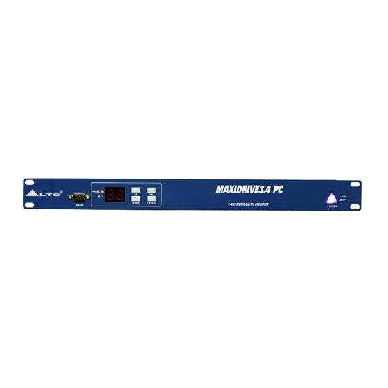
- Page 1 MODEL: MAXIDRIVE 3.4 PC II www.altoproaudio.com Version 1.0 Revised on Jan, 2010...
-
Page 2: Table Of Contents
CONTENTS 1. Introduction……………………………………………………………………………..1 2. Specification…………………………………………………………………………..2 3. Block Diagram…………………………………………………………………....3 4. Schematic Diagram……………………………………………………………....4 5. Wiring Diagram………………………………………………………………….....9 6. PCB Layout………………………………………………………………………..10 7. Test Procedure……………………………………………………………………..15 8. Exploded View & Mechanical Parts List…………………………………………...17 9. BOM List……………………………………………………………………………..19... -
Page 3: Introduction
- 10 Factory PRESETS, each of which can be used as a basic configuration for preparing custom PRESETS, others already optimized for ALTO loudspeaker systems. - 64 User PRESETS, which can be freely programmed to store all the system settings. -
Page 4: Specification
2. Specification Connectors 2* COMBO Nominal Input Sensitivity 0 dB (0.775V) INPUT Section Input Impedance 30 kOhm, electronically balanced Maximum Input level +20 dBu Input Gain -30 / +6dB variable in 0.5 db Steps Connectors 6*XLR-M Output Impedance 600 Ohm, electronically balanced Output Section Nominal Output Level 0 dBu... -
Page 5: Block Diagram
3. Block Diagram Signal Processing Balanced inputs (IN A & IN B). 20-bit A/D converters. LED ladders for monitoring input signals. 5-band parametric equalizers for A & B inputs. 3 delay lines (IN A, IN B & Sum A+B). Routing System for connecting INPUTS and OUTPUTS. Delay lines in 1-6 output. -
Page 6: Schematic Diagram
4. Schematic Diagram --- 4 ---... - Page 7 --- 5 ---...
- Page 8 --- 6 ---...
- Page 9 --- 7 ---...
- Page 10 --- 8 ---...
-
Page 11: Wiring Diagram
5. Wiring Diagram --- 9 ---... -
Page 12: Pcb Layout
6. PCB Layout --- 10 ---... - Page 13 --- 11 ---...
- Page 14 --- 12 ---...
- Page 15 --- 13 ---...
- Page 16 --- 14 ---...
-
Page 17: Test Procedure
4. RS232 JIG TEST (connector for RS232 with a pin 2 end 3 in short circuit) 5. RS485 JIG TEST Adjustments Par. 1: Visual check Check the product appearance upon MAXIDRIVE 3.4 PC II assembly completed before going on following test procedures Par. 2: Connections 2-1. Make sure the main power supply SW is off. - Page 18 7-2. Meanwhile press and hold UP and SEL buttons and then switch on main power supply 7-3. Check if the LCD flashes “AL” about 30 seconds 7-4. Switch off main power SW 7-5. Again switch on main power supply SW of MAXIDRIVE 3.4 PC II, now the LCD displays “AL” Par. 8: DIGITAL INPUT test 8-1.
-
Page 19: Exploded View & Mechanical Parts List
8. Exploded View & Mechanical Parts List --- 17 ---... - Page 20 Mechanical Parts List --- 18 ---...
-
Page 21: Bom List
0011 0012 NE05004 label ALTO PF_V1.2 0013 NB02164 barrier X23,34,40 0014 NB02163 barrier X23,34,40 0015 NB02088 carton (1H) ALTO 19"_V1.1 ND00304 EV foam 3.5t*33.5*42.7mm_V1.5 0016 NA00279 clip-chain bag 0.04t*100*150mm_V1.0 1.warranty card 0017 NA00137 clip-chain bag 0018 0019 MG00025 screw-RS M3*6 1. - Page 22 Class Part No Description Specification Insert location Remark 14P-14P 140mm UL2651 1.PU board CN5 to MPU 0041 HA01645 wire-RS-ACT 28AWG PH1.27 board CN1 HA02191 signle terminal wiring 170mm UL1015 18AWG black 1.PU board S1to grounding 0042 1.MPU board CN2 to PU 0043 HA01590 row-wire connecting wiring 6P-6P 190...
- Page 23 Class Part No Description Specification Insert location Remark RE00008 SMD resistor networks 1/16W 4.7K *4 ±5% 8P 1206(0603x4) AR4,AR5,AR6 0016 0017 RD00327 SMD precise resistor 1/10W 8.20K ±1% 0603 R17,R21,R25,R37,R52,R73 0018 RD00061 SMD fixed resistor 1/10W 10 ±5% 0603 RD00214 SMD precise resistor 1/10W 10.0K ±1% 0603 R71,R9,R11,R65,R79,R7 0019...
- Page 24 Class Part No Description Specification Insert location Remark HK03592 PC board P-MAXI3.4PU-SMD 0001 0001 HB01239 PCB MAXI-PU(1*2)_VER040408 0002 RD00272 SMD precise resistor 1/10W 10.0 ±1% 0603 R106,R107 R102,R5,R6,R67,R7,R72,R73,R78, RD00394 SMD precise resistor 1/10W 68.0 ±1% 0603 0003 R79,R8,R84,R85,R90,R91,R96,R97 R101,R68,R71,R74,R77,R80,R83, 0004 RD00393 SMD precise resistor 1/10W 330 ±1% 0603 R86,R89,R92,R95,R98...
- Page 25 Class Part No Description Specification Insert location Remark 1.voltage converter 0058 NC00089 washer 4* 10*1 grounding MAXIDRIVE3.4 PC NB05891 inner case-RS-CT 0059 CHINA ALTO_V1.0 MAXIDRIVE3.4 PC 0060 MB05898 chassis-RS 85-264V CHINA_V1.1 0061 HK09133 PC board P-ACL2PWRSW SA00185 L.E.D-RS-ACT 3 blue (6554-TLHB4400) 0001 MG00041 screw M3*6...
Need help?
Do you have a question about the MAXIDRIVE 3.4 PC II and is the answer not in the manual?
Questions and answers