
Related Manuals for Alto ALTODRIVE2.3


Summary of Contents for Alto ALTODRIVE2.3
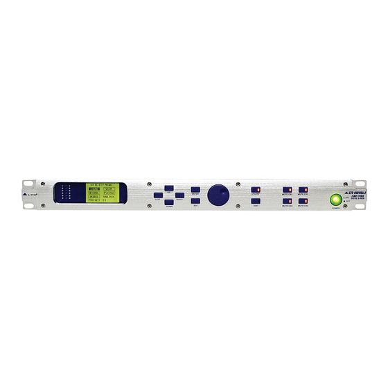
- Page 1 User's Manual 2 WAY STEREO LTODRIVE2.3 DIGITAL X OVER www.altoproaudio.com Version 2.2 September 2005 English English...
- Page 2 Fuse SAFETY RELATED SYMBOLS To prevent fire and damage to the product, use only the recommended fuse type as indicated in this CAUTION manual. Do not short-circuit the fuse holder. Before RISK OF ELECTRIC SHOCK DO NOT OPEN replacing the fuse, make sure that the product is OFF and disconnected from the AC outlet.
- Page 3 PREFACE Dear Customer: Thanks for choosing LTO DRIVE2.3 2-Way Stereo Digital X-Over and thanks for choosing one of the results of AUDIO TEAM job and researches. For our LTO AUDIO TEAM, music and sound are more than a job... are first of all passion and let Us say our obsession! We have been designing professional audio products for a long time in cooperation with some of the major Brands in the world in the audio field.
-
Page 4: Table Of Contents
TABLE OF CONTENTS 1. INTRODUCTION ............................4 2. FEATURE LIST ............................4 FRONT AND BACK PANELS DESCRIPTION ..................4 3.1 The Front Panel 3.2 The Rear Panel 4. INSTALLATION & CONNECTION ......................5 4.1 Power Up and Audio Connections a. -
Page 5: Introduction
1.INTRODUCTION Thank you very much for expressing your confidence in LTO products by purchasing our LTO DRIVE2.3. With the LTO DRIVE2.3 you have acquired an extremely musical and flexible Active Crossover which will provide you also the subwoofer application. Our new LTO DRIVE 2.3 (2 inputs, 4outputs, matrix-like operation X-over) allows the user to work with the quality of the 2/3 by 24 32-bit DSPs, permits extremely precise and fast speakers control and equalization for PA systems with the power of a matrix process allowing each kind of combination in assigning the 2 inputs to the 4 outputs. -
Page 6: The Rear Panel
Power SW with LED (1) Turns the apparatus on and off. Press this SW, the power LED inside the SW will turn on. Dial Control knob (5) Used to change editable values. 3.2 The Rear Panel AC INPUT PUSH PUSH 95-240V 60-50Hz MODEL Rated Power Consumption 15W... -
Page 7: Operational Overview
4.2 Operational Overview At system startup the following splash screens will be shown on the graphic display. LTO DRIVE2.3 Version1.0 Wait Init System LTO DRIVE2.3 is booting and initializing its hardware and software, loading the last used preset and the user interface. -
Page 8: Midi Setup
Name: EMPTY Num: Using Left and Right keys the user can move into the string, with the dial the blinking character can be edited, Enter confirms the choice and Esc cancels operation allowing to maintain the old preset name. Upon confirmation the new preset name will be shown in the lower left corner of the window and in the name field. -
Page 9: Edit Menu
0 0 0 0 0 0 With the Up/Down key it's possible to select the Password, New Password and page number items; selection is highlighted printing the item in reverse color. 0 0 0 0 0 0 To have complete access to the system, the fields PASSWORD and NEW PASSWORD must match. If the user wants to restrict system access, it is sufficient to change the PASSWORD field. -
Page 10: In L/In R
With the Up/Down keys it is possible to select the inputs and the outputs sequentially. In the pictures below the selection sequence is shown. The Right/Left keys make/cut the connection between the selected input and output. In the case above, pressing the Right key, the Left channel will be connected to the OUT 3 channel. - Page 11 This graphic screen shows the frequency response of the channel. Use Up/Down/Left/Right keys to select one of the five fields: Page Number, Filter Number, Gain, Frequency, Band- width. The selected value can be changed by means of the dial. The selected filter's frequency will be shown by a vertical segment on the display (see above).
- Page 12 This graphic screen shows the frequency response of the channel. Use Up/Down/Left/Right keys to select one of the five fields: Page Number, Filter Number, Gain, Frequency, Band- width. The selected value can be changed by means of the dial. The selected filter's frequency will be shown by a vertical segment on the display (see above).
-
Page 13: Application Illustration
POL. POL. THR. 00 dB THR. 00 dB REL. 0.4 S REL. 0.4 S ATK. 0.05 S ATK. 0.05 S POL. POL. THR. 00 dB THR. 00 dB REL. 0.4 S REL. 0.4 S ATK. 0.05 S ATK. 0.05 S POL. -
Page 14: Lto Drive2.3 2-Way Input, 4- Way Output (High, High, Low, Low Level)
SUB AMP PROFESSIONAL HIGH POWER STEREO AMPLIFIER PROT PROT CLIP CLIP CLIP CLIP POWER POWER CH-A CH-A CH-B CH-B LOW AMP PROFESSIONAL HIGH POWER STEREO AMPLIFIER PROT PROT CLIP CLIP CLIP CLIP POWER POWER CH-A CH-A CH-B CH-B MID AMP PROFESSIONAL HIGH POWER STEREO AMPLIFIER PROT PROT... -
Page 15: Appendix
6.APPENDIX LTO DRIVE2.3 Midi standard control PROGRAM CHANGE Parameter Value Legend Preset 01 Factory Preset Preset 02 to preset 65 1, 2, 3,.., 64 User Preset CONTROL CHANGE Parameter Controller Value setting Legend Bank 0, 1, 2 Mode Channel 0, 1 Input Left, Input Right Mode Channel 2, 3, 4, 5... - Page 16 MIDI Controllers Values Amplitude 15dB / 15dB step 0.5dB (Value = d u) d \ u 15.0dB 14.5dB 14.0dB 13.5dB 13.0dB 12.5dB 12.0dB 11.5dB 11.0dB 10.5dB 10.0dB 09.5dB 09.0dB 08.5dB 08.0dB 07.5dB 07.0dB 06.5dB 06.0dB 05.5dB 05.0dB 04.5dB 04.0dB 03.5dB 03.0dB 02.5dB 2.0dB...
-
Page 17: Technical Specifications
7.TECHNICAL SPECIFICATIONS Input Channel Digital Input Gain /+ 12 dB / step 0.5 dB Gain /+ 15 dB / step 0.5 dB 4 Parametric Filters Freq 20 Hz 20 KHz step 1/12 oct BandWidth 0.05 oct 3 oct / step 0.05 oct Delay line Up to 512 ms minimum step 21us Output Channel... - Page 18 Power Supply Connector type 3 poles DIN (female) Type Servo controlled, Switching Fuse 210 240V: T250mAL 250VAC 95 120V: 500mAL 250VAC AC input 95 240V~60 50Hz Rated power consumption User Interface Graphic display 128 64 dots Keyboard 6 LEDs/12user's keys Vu meter 2 6 LEDs Physical...
-
Page 19: Warranty
8. WARRANTY 1. WARRANTY REGISTRATION CARD To obtain Warranty Service, the buyer should first fill out and return the enclosed Warranty Registration Card within 10 days of the Purchase Date. All the information presented in this Warranty Registration Card gives the manufacturer a better understanding of the sales status, so as to purport a more effective and efficient after-sales warranty service. - Page 20 No. 1, Lane 17, Sec. 2, Han Shi West Road, Taichung 40151 Taiwan http://www.altoproaudio.com Tel: 886-4-22313737 email: alto@altoproaudio.com Fax: 886-4-22346757 All rights reserved to ALTO. All features and content might be changed without prior notice. Any photocopy, translation, or reproduction of part of this manual without written permission is forbidden. Copyright 2005 SEIKAKU GROUP NF 01200-2.2...
Need help?
Do you have a question about the ALTODRIVE2.3 and is the answer not in the manual?
Questions and answers
Cara faktory reset AltoDrive2.3 seperti apa?