AUSTRALIAN MONITOR AMIS60 Installation And Operation Manual
Amis installation series 60w / 120w mixer amplifier
Hide thumbs
Also See for AMIS60:
- Service manual (26 pages) ,
- Brochure (2 pages) ,
- Operating manual (10 pages)

Related Manuals for AUSTRALIAN MONITOR AMIS60


Summary of Contents for AUSTRALIAN MONITOR AMIS60
- Page 1 A M I S S E R I E S 6 0W / 120 W M IX ER A M PLIF IER I N S TA L LATI O N A N D O PER ATIO N M ANUAL AMIS SERIES 60/120 manual.indd 2/7/07 12:42:31 PM...
- Page 2 I MPO RTA NT SA FETY I N FOR MATI ON 1. Save the carton and packing material even if the equipment has 13. Do not block fan intake or exhaust ports. Do not operate equipment arrived in good condition. Should you ever need to ship the unit, use on a surface or in an environment which may impede the normal flow only the original factory packing. of air around the unit, such as a bed, rug, weathersheet, carpet, or completely enclosed rack. If the unit is used in an extremely dusty 2. Read all documentation before operating your equipment. Retain or smoky environment, the unit should be periodically “blown free” all documentation for future reference. of foreign matter. 3. Follow all instructions printed on unit chassis for proper operation. 14. Do not remove the cover. Removing the cover will expose you to potentially dangerous voltages. There are no user serviceable 4. Do not spill water or other liquids into or on the unit, or operate parts inside. the unit while standing in liquid. 15. Do not drive the inputs with a signal level greater than that required 5. Make sure power outlets conform to the power requirements listed to drive equipment to full output. on the back of the unit. 16. Do not connect the inputs / outputs of amplifiers or consoles to any 6. Do not use the unit if the electrical power cord is frayed or broken.
-
Page 3: Table Of Contents
I N T R O D U C T I O N A N D C O N T E N T S The AMIS60 and AMIS120 mixer amplifiers are designed for commercial IN TR O D U C TIO N installations. Both models operate on 230/240 VAC, 50Hz (115VAC, 60Hz) or 24 VDC, and may be desk or rack mounted (rack mount kit supplied fitted). The FRON T PA NE L AMIS60 will deliver 60 watts into a load of 8 ohms, 70 volt or 100 volt line. -
Page 4: A M I S S E R I E S I N S Ta L L At I O N & O P E R At I O N M A N U A L
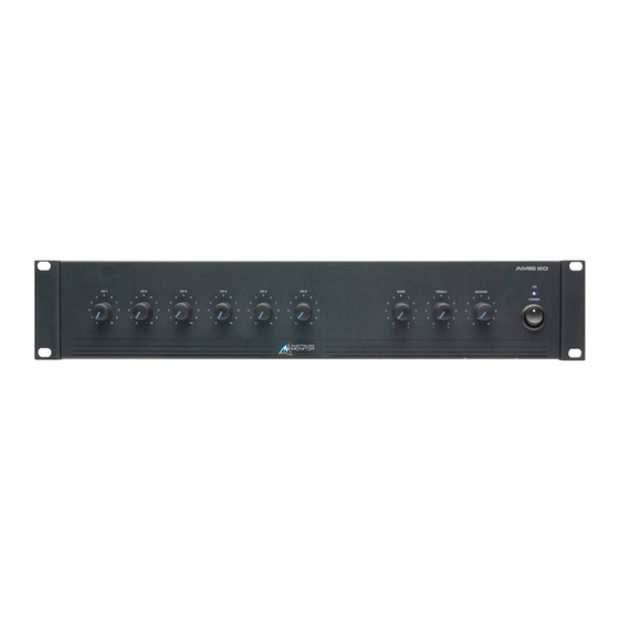
F R O N T PA N E L CH 1-6 These control the individual level for each channel input. BASS There is 12dB of cut and boost at 100Hz. This EQ is the shelving type. TREBLE There is 9dB of cut and boost at 10kHz. This EQ is the shelving type. MASTER This controls the overall output level. This LED indicates the unit is powered “on”. NOTE: When using the “24VDC” in terminals, the amplifier is ‘on’ and the power LED will always be on regardless of the position of the power switch. POWER This switch switches power on or off from the mains. The up position is on. NOTE: When using the “24VDC” in terminals, the amplifier is ‘on’ regardless of the switch position. PA G E 4 A M I S S E R I E S I N S TA L L AT I O N & O P E R AT I O N M A N U A L AMIS SERIES 60/120 manual.indd 2/7/07 12:42:32 PM... -
Page 5: Rea R Pa N El
R E A R PA N E L CH 1-6 VCA CONTROL Tones available on the AMIS60 and AMIS120 are: - Evacuation Tone Each channel input section has two inputs: These two terminals provide connection for an external - Alert Tone XLR input – This is a balanced microphone input. It has an potentiometer (500k log) which is available mounted on - Bell Tone input sensitivity of 1mV. a wall panel from Australian Monitor (RC1). When the - Pre-Announce Chime RCA input – This is an unbalanced line level input. It has potentiometer is connected it allows for remote control an input sensitivity of 150mV. The two RCA sockets are of the master level. The external pot is governed by the TELEPHONE INPUT (only on 115V models) summed to mono internally. master level of the amplifier allowing the installer to set the volume and then lock the amplifier in a rack, leaving The 600 ohm transformer balanced Telephone Input is REC OUTPUT the user with just a master volume control that cannot go paralleled with input 2. If telephone paging is required, beyond the level set on the front panel master control. the XLR & dual RCA inputs should not be used as these The REC output is on unbalanced RCA connectors. The The terminals can also be used as a system mute by inputs will be summed with the Telephone Input into output level is 300mV into 10kohm at rated output. The shorting the two contacts together (by a relay or switch channel 2. The front panel level control will set the gain... -
Page 6: In S Ta L Latio N
I N S TA L L AT I O N MOUNTING OUTPUT CONNECTIONS When rack mounting, it is advisable to allow 1 rack space above and below The output terminal strip accepts wire sizes from the amplifier. When multiple amplifiers are mounted in a rack, exhaust fans 16-22AWG (1.5mm2 - 0.35mm2). should be used on the rack. Airflow for cooling the amplifier is by convec- The following table should be used as a guideline for cable sizes. Regula- tion from bottom to top and by fan left to right. tions in your area may require different gauged wire and should be checked before using. OUTPUT DISTANCE WIRE SIZE AMC60 AMC120 100V Up to 50m AWG26(0.12mm AWG24(0.2mm 50m–200m AWG20(0.5mm AWG18(0.75mm Over 200m AWG18(0.75mm AWG16(1.5mm 70V Up to 50m AWG24(0.2mm AWG22(0.35mm 50m–200m AWG18(0.75mm AWG16(1.5mm... -
Page 7: Setu P & Tr O U B Le Sh O O Ting
S E T U P & T R O U B L E S H O O T I N G Levels Volume controls should aimed to be set at nominal, which is at the half or 12o’clock position. Any unused channels should be set to minimum. When establishing a mix, remember: Less is more. TR O U B L E SH O O T I N G GUI DE TROUBLE LIKELY CAUSE REMEDY Power LED not on... -
Page 8: Dimen S Io Ns
D I M E N S I O N S PA G E 8 A M I S S E R I E S I N S TA L L AT I O N & O P E R AT I O N M A N U A L AMIS SERIES 60/120 manual.indd 2/7/07 12:42:35 PM... -
Page 9: Bloc K D Ia G R A M
B L O C K D I A G R A M PA G E 9 A M I S S E R I E S I N S TA L L AT I O N & O P E R AT I O N M A N U A L AMIS SERIES 60/120 manual.indd 2/7/07 12:42:35 PM... -
Page 10: Spec Ific At Io N S
S P E C I F I C AT I O N S AMIS 60 AMIS 120 POWER OUTPUT (0.5%THD, 1KHZ) 60W 120W S/N RATIO > 76dBr > 76dBr POWER BANDWIDTH (-3DB +1DB) 60Hz-15kHz 60Hz-15kHz OUTPUT REGULATION 90% 90% SIZE (WXHXD) 482x88x313.5mm 482x88x313.5mm 19”x3.5”x12.3”... - Page 11 S P E C I F I C AT I O N S AMIS 60 AMIS 120 MAINS CURRENT DRAW (240V) FULL POWER 0.75A 1.5A 1/3 POWER 0.50A 0.95A 1/8 POWER 0.40A 0.65A IDLE 0.25A 0.15A MAINS CURRENT DRAW (115V) FULL POWER 1.6A 3.1A...
- Page 12 AUSTRALIA AND NEW ZEALAND w w w. a u s t r a l i a n m o n i t o r. c o m . a u SYDNEY MELBOURNE BRISBANE ADELAIDE PERTH AUCKLAND (SA & NT SALES) (NSW &...
Need help?
Do you have a question about the AMIS60 and is the answer not in the manual?
Questions and answers