Table of Contents
Advertisement
Quick Links
™
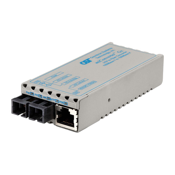
miConverter
GX/T
Media Converter
User Manual
Unit shown with optional wall-mounting bracket kit
DESCRIPTION
The
miConverter GX/T
is a 10/100/1000BASE-T UTP
to 1000BASE-X fiber media converter that supports
jumbo frames up to 10,240 bytes. The
GX/T
features
fixed fiber and Small Form Pluggable (SFP) transceivers
that support multimode, single-mode and single-mode
single-fiber options.
Both the fiber port and the UTP port support auto-
negotiation, an IEEE standard which defines how all the
communicating devices automatically perform their
configuration functions.
The auto-negotiation feature can be disabled on both
ports (for manual configuration) using DIP-switches on
the product. This is useful in a situation where the
GX/T
is connected to a non-negotiating device and the
configuration parameters must be set manually.
Page 1
DIP-SWITCH SETTINGS
Link Propagate "LP"
UTP Mode 1
UTP Mode 2
F/O Manual Negotiate "Man"
UP
DOWN
F/O Auto-negotiate "AN"
UTP Mode 2
UTP Mode 1
Link Segment "LS"
Fig. 1 DIP-switches
Link Segment/Link Propagate "LS/LP" DIP-switch
Setting the DIP-switch to LS (Link Segment), a port
transmits a Link signal independently of any received
Link at any other port. For example, the UTP transmits
a Link regardless of the fiber receiving a Link [Fig. 2(a)
& (b)].
Setting the DIP-switch to LP (Link Propagate), a port
transmits a Link signal only when receiving a Link at
its other port. For example, the UTP transmits a Link
only when receiving a Link at the fiber port [Fig. 2(c)].
Page 5
Connector Type
Fiber Type
Distance
ST
SC
SFP
SFP
-
-
-
1239-0-x
MM
220 / 550m
1
1220-0-x
1222-0-x
SM
12km
1221-1-x
1223-1-x
SM
34km
-
1223-2-x
SM
80km
-
1223-3-x
SM
110km
-
1223-4-x
-
1223-5-x
SM
140km
SM-SF
20km
-
1230-1-x
1310/1550
SM-SF
20km
-
1231-1-x
1550/1310
SM-SF
-
1230-2-x
40km
1310/1550
SM-SF
-
1231-2-x
40km
1550/1310
When choosing power options, replace (-x) in the model number
with the suffix number that corresponds to the selected power
supply.
-1
US Power Supply - 120Volt / 60Hz
-2
Universal Power Supply (requires AC power cord) - 100-240Volt / 50-60Hz
-3
European Power Supply - 100-240Volt / 50-60Hz
-4
UK Power Supply - 100-240Volt / 50-60Hz
-5
Australian Power Supply - 100-240Volt / 50-60Hz
-6
USB Power Adapter Cable
-8
US/JPN Power Supply - 100-240Volt / 50-60Hz
-9
2 Pin Terminal Connector
Example: 1223-3-6 = SM / DF / 80KM with a USB Power Adapter
Cable.
For power supplies -3, -4 -5 and -8, country/region specific clips
are used to provide the necessary power connection.
Single-Fiber converters must be used in pairs. The Tx wavelength
on one end has to match the Rx wavelength on the other.
Page 2
LS
LS
Fiber
UTP
UTP
(A)
UTP
Fiber
UTP
Switch 1
Converter A
Converter B Switch 2
LS
LS
(B)
Switch 1
Converter A
Converter B Switch 2
LP
LP
(C)
Switch 1
Converter A
Converter B Switch 2
LED Lit
LED Lit
LED Off
Fig. 2 Link Modes
UTP Mode Configuration DIP-Switches
See the table on page 7.
When configured for auto-negotiation, Pause is always
advertised. Each port will resolve Pause capability
independently during auto-negotiation. If NO Pause is
resolved, the port will not send or respond to Pause
frames.
Page 6
Before inserting the Power Adapter, verify
that the power on the adapter is appropriate
-
for your AC line voltage source.
-
-
POWER ADAPTER NOTICE
-
-
This product should only be used with Omnitron supplied
-
Power Supply model numbers 9113-PS, 9115-PS,
-
9116-PS-3, 9116-PS-4, 9116-PS-5 or 9116-PS-8.
-
When powering the
miConverter GX/T
-
Power Adapter cable (P/N 9130-2), the cable must be
connected to a Full-Powered USB Type-A port (5V,
-
500mA).
Note: Not all USB Type-A ports are Full-Powered
USB ports.
INSTALLATION PROCEDURE
1.) Configure the appropriate
DIP-Switch settings.
2.) Connect the UTP port via a Category 5 or better
cable to a 10BASE-T, 100BASE-TX or 1000BASE-T
Ethernet device.
3.) When using fixed fiber port models, connect the
appropriate multimode or single-mode fiber cable to the
fiber port of the installed module. It is important to
ensure that the transmit (Tx) is attached to the receive
side of the device at the other end and the receive (Rx)
is attached to the transmit side. Single-fiber (SF) media
converter models operate in pairs. The Tx wavelength
must match the Rx wavelength at the other end and
Page 3
UTP
UTP
UTP Mode of Operation
Mode 1
Mode 2
Configured for Auto Negotiation.
Down
Down
(1000F, 1000H, 100F, 100H, 10F,
10H and Pause capable)
Down
Up
Manual 10M FDx
Up
Down
Manual 100M HDx
Up
Up
Manual 100M FDx
When the module is configured for auto-negotiation, the
module will advertise in the order shown in the parenthesis.
F/O Manual/Auto "Man/AN" DIP-Switch
Setting this DIP-Switch to Auto-Negotiate "AN" (factory
setting) enables the fiber port to determine duplex mode
automatically. If a connection can not be established,
the fiber port will automatically attempt to connect to
the device by reconfiguring to manual mode.
If the connected device cannot provide the proper
signal to indicate its own mode of operation or the fiber
port can establish a link after attempting a manual
connection, this DIP-Switch should be set to Manual
"Man." This feature allows connections with legacy
devices that do not support auto-negotiation.
NOTE: When the fiber port is configured for Manual
Mode, a link may not occur with the connected
device. Configure both devices to Manual mode
to establish a link.
Page 7
the Rx wavelength must match the Tx wavelength at
the other end.
4.) When using a
Fiber transceiver into the Port 1 SFP receptacle on the
GX/T.
NOTE: The release latch of the SFP Fiber transceiver
must be in the closed (up) position before insertion.
5.) Mount the
miConverter GX/T
Velcro
®
strips or optional wall-mounting bracket kit
(P/N 1091-0).
using the USB
6.) To power the unit using the AC/DC adapter, connect
the AC/DC adapter to the AC outlet. Then connect the
barrel plug at the end of the wire on the AC/DC adapter
to the 2.5mm DC barrel connector (center-positive) on
the unit. Confirm that the unit has powered up properly
by checking the power status LED located on the front
of the unit.
To power the unit using a DC power source, prepare a
miConverter GX/T
power cable using a two-conductor insulated wire (not
supplied) with a 14 AWG gauge minimum. Cut the
power cable to the length required. Strip approximately
3/8 of an inch of insulation from the power cable wires.
Connect the power cables to the
the stripped ends to the DC power connector.
Connect the power wires to the DC power source. The
Power LED should indicate the presence of power.
WARNING: Note the wire colors used in making
the positive and negative connections. Use the
same color assignment for the connection at the
DC power source.
LED INDICATORS
LED Function
Color
"Legend"
Power
Green
No power
"Power"
Fiber Activity
Green
No actvity
"F/O Link-Act"
F/O AN
Port configured for
Green
"F/O-Auto-Neg"
manual negotiation
F/O Activity
+
Green
NA
F/O AN
UTP Activity
Green
No activity
"100 Link-Act"
UTP Activity
Green
No activity
"1000 Link-Act"
UTP Activity
"10 Link-Act"
Green
No activity
(100 + 1000)
GX/T
SFP model, insert the SFP
using the included
GX/T
unit by fastening
Page 4
On / Blinking State
Off State
On: Module has power
On: UTP port linked at 1000Mbps
Blinking (10Hz): Link activity at
1000Mbps
Blinking (1Hz): Energy detected
On: Fiber port configured for AN
Blinking (1Hz): Configured as AN
but linked in Manual mode
Synchronized Blinking (1Hz):
AN error or Remote Fault bit
detected
On: UTP port linked at 100Mbps
Blinking (10Hz): Link activity at
100Mbps
On: UTP port linked at 1000Mbps
Blinking (10Hz): Link activity at
1000Mbps
On: UTP port linked at 10Mbps
Blinking (10Hz): Link activity at
10Mbps
Page 8
Advertisement
Table of Contents

Related Manuals for Omnitron Systems Technology miConverter GX


Summary of Contents for Omnitron Systems Technology miConverter GX
- Page 1 (up) position before insertion. 110km 1223-4-x This product should only be used with Omnitron supplied 1223-5-x 140km 5.) Mount the miConverter GX/T using the included Power Supply model numbers 9113-PS, 9115-PS, SM-SF 20km 1230-1-x Velcro ®...
- Page 2 Address: Omnitron Systems Technology, Inc. to do so by Omnitron Systems Technology, Inc. equipment (including removal of equipment cover by personnel not specifically authorized and Warranty 140 Technology #500...
Need help?
Do you have a question about the miConverter GX and is the answer not in the manual?
Questions and answers