Table of Contents
Advertisement
Quick Links
The contents of this manual are based on the
latest product information available at the
time of publication. Pacific reserves the right
to make changes or improvements to its
machines without notice.
For new manuals write to:
Triple S
2 Executive Park Drive
Billerica, MA 01862
or download the most recent version of the
manuals from our website:
www.triple-s.com
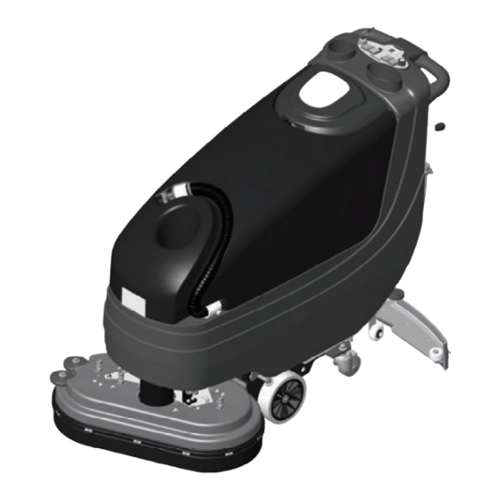
Ace 26T1 Auto Scrubber
Carefully inspect all components to ensure
that there is no concealed freight damage. If
such damage is discovered, file a
"CONCEALED DAMAGE REPORT"
immediately with the delivering carrier.
FOR YOUR CONVENIENCE, RECORD
THE FOLLOWING IMPORTANT
INFORMATION:
SERIAL NUMBER
DATE PURCHASED
Page 1 of 35
Advertisement
Table of Contents

Related Manuals for Triple S Ace 26T1


Summary of Contents for Triple S Ace 26T1
- Page 1 Ace 26T1 Auto Scrubber Carefully inspect all components to ensure The contents of this manual are based on the that there is no concealed freight damage. If latest product information available at the such damage is discovered, file a time of publication. Pacific reserves the right “CONCEALED DAMAGE REPORT”...
-
Page 2: Safety Instructions
SAFETY INSTRUCTIONS You must have training in the operation of the machine before using it. READ THE INSTRUCTION BOOK. If you do not understand any instruction, ask your supervisor. Make sure all labels, decals, warnings, cautions and instructions are fastened to the machine. - Page 3 SYMBOLS USED ON THE AUTOMATIC SCRUBBER Water Valve Indicator Brush Drive Motor Control Switch Vacuum Motor Control Switch Battery Charge Indicator Main Machine Power Key Switch Forward – Reverse Traction Drive Switch Traction Drive Speed Control Squeegee Lift Control Lever Solution Flow Rate Adjusting Lever Page 3 of 35...
-
Page 4: Machine Preparation
MACHINE PREPARATION 1) UNPACKING THE MACHINE a) Take off the outer packaging. b) The machine is fastened to the pallet with wooden wedges that block the wheels. Remove tie down straps. c) Disconnect traction motor black lead wire located near the vacuum motor support. -
Page 5: Battery Charge Level Indicator
MACHINE PREPARATION BATTERY INSTALLATION (Cont.) d) Place the batteries in the battery compartment. e) Connect the battery connector to the machine connector f) Replace the recovery tank and reassemble the vacuum cover and squeegee hose. Machine Connector Battery Connector 3) BATTERY CHARGE LEVEL INDICATOR The battery indicator is digital with 4 display levels and a flashing one. - Page 6 MACHINE PREPARATION 4) SQUEEGEE ASSEMBLY INSTALLATION Vacuum The squeegee is assembled to the machine Outlet by lifting the locking latches and sliding the squeegee assembly onto the 2 posts at the rear of the squeegee swing arm. Push on the locking latches down.
-
Page 7: Recovery Tank
MACHINE PREPARATION 7) RECOVERY TANK Vacuum Open the lid and confirm the following Cover connections are secure: a) The vacuum cover is securely attached. Align the notches and rotate the cover clockwise to close. The vacuum hose must also be attached. b) Confirm that the squeegee hose is properly Squeegee connected. -
Page 8: Machine Operation
MACHINE OPERATION 1) Connect machine connector to the battery Machine connector. Connector Battery Connector 2) Turn on the main power key switch. Battery Vacuum Battery charge indicator will illuminate indicating the Main Power Motor Charge charge level of the batteries. If the indicator is Key Switch Switch Indicator... -
Page 9: Overfill Protection
MACHINE OPERATION 10) MACHINE MOTION This machine is equipped with traction wheel Traction Drive propulsion. To move machine forward, rock Speed Control traction directional switch forward and depress the handle switch lever. Adjust the forward speed with the traction drive speed control knob. During the first few yards of operation, check that the quantity of the cleaning solution is sufficient to wet the floor and that the squeegee dries the... - Page 10 UPON COMPLETION OF MACHINE USE After finishing your work and before any type of maintenance is done, it is necessary to do the Squeegee following: Lift Lever 1) Close the water valve by raising the solution flow control lever. 2) Raise the brush base by stepping down Parking Brake locking the brush base lift lever.
-
Page 11: Cleaning The Recovery Tank
DAILY MACHINE MAINTENANCE CLEANING THE RECOVERY TANK 1) Empty the recovery tank by removing the drain plug from the drain hose. WARNING: Use gloves for protection from contact with dangerous solution. Drain Plug 2) Lift the cover of the recovery tank. Vacuum 3) Take off the vacuum cover by rotating it Cover... -
Page 12: Cleaning The Squeegee
DAILY MACHINE MAINTENANCE CLEANING THE SQUEEGEE Vacuum To obtain the best drying results, keep the Outlet squeegee clean. To clean the squeegee it is necessary to: 13) Remove the vacuum hose from the squeegee. 14) Lift locking latches. Remove the squeegee assembly by pulling rearward. - Page 13 DAILY MACHINE MAINTENANCE BRUSH / PAD DRIVER REMOVAL 24) Lift the brush base by depressing the foot level at the rear of the machine. 25) The photo shows the directions to rotate the brushes to unlock them from the auto scrubber.
-
Page 14: Cleaning The Squeegee Hose
WEEKLY MACHINE MAINTENANCE CLEANING THE SQUEEGEE HOSE Do Not To obtain the best drying results, keep the Wash squeegee hose clean. To clean the squeegee Vacuum hose it is necessary to: Cover 1) Take off the vacuum hose from its vacuum Hose port on the squeegee. - Page 15 WATER SOLENOID MAINTENANCE In the event that the water solenoid begins to leak when turned off debris must be cleared at the valve seat. To gain access the water solenoid the scrub deck most be disassembled from the lifting arms. Remove the 4 bolts shown in the photo to release the scrub deck.
-
Page 16: Troubleshooting Guide
TROUBLE SHOOTING GUIDE 1) INSUFFICIENT WATER TO THE BRUSHES Solution a) Make sure the solution flow control valve is open. Flow Control b) Confirm that there is water in the solution tank. Lever c) Make sure solution dispensing tubes are not clogged or obstructed. -
Page 17: Brush Deck Assembly
Brush Deck Assembly Drawing 1 Page 17 of 35... - Page 18 Drawing 1 PART NUMBER DESCRIPTION & SPECIFICATION NOTE 840502 Adjuster Bolt 840901 Brush Optional 840904 Carbon Brush 841102 Wheel Bushing 841110 Bushing 841111 Bushing 841308 Brush Drive Belt 841309 Bearing 842312 Base Cover 842706 Brush Deck 843302 Fitting Barbed 843306 Fitting Barbed 843307 Fitting...
-
Page 19: Main Frame Assembly
Main Frame Assembly Drawing 2 Page 19 of 35... - Page 20 Drawing 2 PART NUMBER DESCRIPTION & SPECIFICATION NOTE 840308 Brake Lever Arm Shaft 840310 Brush Deck Lift Idler Arm Weldment 840311 Strengthening Shaft 841108 Bushing 841112 Bushing 842003 Hose Clamp 842008 Clamp Bar 842306 Pedal Cover 842311 Pedal Cover - Brake 842701 Metal Disc 843203...
-
Page 21: Squeegee Arm Assembly
Squeegee Arm Assembly Drawing 3 Page 21 of 35... - Page 22 Drawing 3 PART NUMBER DESCRIPTION & SPECIFICATION NOTE 840304 Squeegee Link Arm Weldment 840501 Squeegee Adjuster Bolt Rod 841103 Wheel Bushing 842405 Squeegee Lift Cable 842407 Squeegee Lift Cable 845001 Knob Handle 845601 Squeegee Mount Base 845602 Squeegee Mount Base Pivot 846701 Squeegee Attachment Pin 847302...
-
Page 23: Squeegee Assembly
Squeegee Assembly Drawing 4 Page 23 of 35... - Page 24 Drawing 4 PART NUMBER DESCRIPTION & SPECIFICATION NOTE 840703 Squeegee Blade Front 840704 Squeegee Blade Rear 841304 Squeegee Attachment Block 842012 Band Clamp-Rear 842013 Band Clamp-Front 843205 Squeegee Frame Weldment 843317 Filler - Squeegee 845104 Latch ASM 845105 Squeegee Attachment Block Latch 881145 Wheel Bushing 889742...
-
Page 25: Solution Tank Assembly
Solution Tank Assembly Drawing 5 Page 25 of 35... - Page 26 Drawing 5 PART NUMBER DESCRIPTION & SPECIFICATION NOTE 841300 Rear Battery Bracket 841303 Side Battery Bracket 842003 Hose Clamp 842705 Sound Deadener 843308 Fitting Barbed 843309 Fitting Barbed 843310 Filter Basket 843401 Battery Plastic Gasket 843402 Side Battery Gasket 843404 Conical Tank Gasket 844702 Fitting...
-
Page 27: Recovery Tank Assembly
Recovery Tank Assembly Drawing 6 Page 27 of 35... - Page 28 Drawing 6 PART NUMBER DESCRIPTION & SPECIFICATION NOTE 842007 Hose Clamp 842305 Solution Tank Cover 842308 Recovery Tank Cover 842403 Chain 842411 Chain For Lift 843405 Tank Gasket 844101 Recovery Tank Vacuum Hose 844102 Squeegee Vacuum Hose 844103 Drain Hose 845110 Recovery Tank Cover Label 845131...
-
Page 29: Vacuum Assembly
Vacuum Assembly Drawing 7 Page 29 of 35... - Page 30 Drawing 7 PART NUMBER DESCRIPTION & SPECIFICATION NOTE 840305 Lever Arm Weldment ZINC 840805 Bracket-Weldment EPOXY PAINT 841104 Bushing BRASS 841305 Lever Bracket ZINC 842014 Hose Clamp 50mm 842702 Vacuum Motor Sound Deadener 842703 Vacuum Motor Sound Deadener 842704 Sound Deadener 843801 Grommet 843901...
-
Page 31: Switch Box Assembly
Switch Box Assembly Drawing 8 Page 31 of 35... - Page 32 Drawing 8 PART NUMBER DESCRIPTION & SPECIFICATION NOTE 841306 Bezel - Rocker Switch 842301 Cover Upper Switch Box 842302 Cover Lower Switch Box 842307 Cover - Rocker Switch 842310 Cover - Small Rocker Switch 843801 Grommet 844001 Fuse Holder 844703 Insulator 845101 Scrubber Lever - Switch Box...
-
Page 33: Electrical Schematic
Electrical Schematic Drawing 9 Page 33 of 35... - Page 34 Drawing 9 PART NUMBER DESCRIPTION & SPECIFICATION NOTE 844507 Wire Harness 844509 Wire Harness 844514 Wire Harness 844518 Wire Harness 844519 Wire Harness 844520 Wire Harness 844521 Wire Harness 844522 Wire Harness 844526 Wire Harness 844527 Wire Harness 844530 2 Cables black-red and connector 50A 844539 Wire Harness 844542...
- Page 35 If unable to locate the Dealer, you may contact Triple S at the address listed herein for the location of the nearest Triple S repair center or agent or for other instructions pertaining to your warranty difficulty.
Need help?
Do you have a question about the Ace 26T1 and is the answer not in the manual?
Questions and answers