Table of Contents
Advertisement
Quick Links
HP UPS R5500 ERM
Installation Instructions
June 2006 (Third Edition)
Part Number 351641-003
Overview
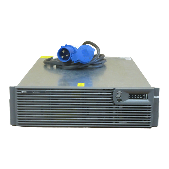
The ERM consists of two battery packs in a 3U chassis. The
ERM connects directly to a UPS R5500 or to another ERM. Up
to two ERM units can be connected.
At the HP recommended 80 percent load, one ERM extends
the available UPS runtime up to 30 minutes.
For more information about any of the topics covered in this
document, see the UPS user guide located on the
documentation CD or HP website
(http://www.hp.com/go/rackandpower).
Precautions
WARNING: A risk of personal injury from
electric shock and hazardous energy levels
exists. The installation of options and routine
maintenance and service of this product
must be performed by individuals who are
knowledgeable about the procedures,
precautions, and hazards associated with AC
power products.
This symbol indicates that the ERM
exceeds the recommended weight for
one individual to handle safely.
75 kg
WARNING: To reduce the risk of
167 lb
personal injury or damage to the
equipment, observe local occupational
health and safety requirements and
guidelines for manual material
handling.
CAUTION: Always plan the rack installation so that
the heaviest item is on the bottom of the rack. Install
the heaviest item first, and continue to populate the
rack from the bottom to the top.
ERM kit contents
•
Important Safety Information guide
•
This document
•
Warranty information
•
Rails, with mounting hardware for square- and
round-holed racks
•
ERM
•
Front bezel
•
Rear mounting brackets, plates, and
associated hardware
Advertisement
Table of Contents

Related Manuals for HP UPS R5500 ERM


Summary of Contents for HP UPS R5500 ERM
- Page 1 ERM connects directly to a UPS R5500 or to another ERM. Up Installation Instructions to two ERM units can be connected. At the HP recommended 80 percent load, one ERM extends the available UPS runtime up to 30 minutes. For more information about any of the topics covered in this...
-
Page 2: Tools And Materials
If the date on the battery recharge The following items are supplied with the rack: date label has passed without the battery being • Screws recharged, contact an HP authorized service • Hex nuts representative for directions. •... -
Page 3: Preparing The Rails For Integrated Shipping
Install cage nuts or clip nuts into the rear of the rack. Preparing the rails for integrated shipping If the unit is to be shipped in an HP 9000 or 10000 series rack: Remove the hex nuts, flat washers, and lock washers from the mounting rail. -
Page 4: Powering Down The Ups
Powering down the UPS Install the mounting ears on the chassis using the screws provided. Shut down all load devices. Press the Standby button to take the UPS out of Operate mode. Power to the load receptacles ceases. Disconnect the UPS from utility power. Wait at least 60 seconds for the UPS internal circuitry to discharge. -
Page 5: Connecting The Erm To The Ups
Configuring the UPS Connecting the ERM to the UPS After the ERMs are installed, place the UPS in Configure mode, and use the UPS front panel controls and LED indicators to configure the UPS for the number of attached ERMs. Other UPS parameters that can also be configured are the nominal utility voltage level and Site Wiring Fault detection. -
Page 6: Ups Front Panel Led Indicators
© Copyright 2003, 2006 Hewlett-Packard Development Company, L.P. The information contained herein is subject to change without notice. The only warranties for HP products and services are set forth in the express warranty statements accompanying such products and services. Nothing herein should be construed as constituting an additional warranty.
Need help?
Do you have a question about the UPS R5500 ERM and is the answer not in the manual?
Questions and answers