Table of Contents
Advertisement
Integra High Output Remote Control
Inset Live Fuel Effect Gas Fire
Installation and
Users Instructions
These instructions should be read by the
installer before installation and then should be
handed to the end user when the installation
is complete.
This is an official requirement and is the
responsibility of the fitter of this
appliance.
Having installed the appliance, the installer
should take the necessary steps to ensure
that the user fully understands how to operate
the appliance and is also made aware of the
fire's basic cleaning and maintenance
requirements.
Advertisement
Table of Contents

Subscribe to Our Youtube Channel
Related Manuals for Cast Tec Integra

Summary of Contents for Cast Tec Integra
- Page 1 Integra High Output Remote Control Inset Live Fuel Effect Gas Fire Installation and Users Instructions These instructions should be read by the installer before installation and then should be handed to the end user when the installation is complete. This is an official requirement and is the responsibility of the fitter of this appliance.
-
Page 3: Table Of Contents
CONTENTS SECTION PAGE Notes for the Installer and End User Installation Requirements Installation Procedure - Standard 22” x 16” Installation Procedure - Decorative Cast Commissioning Technical Data Replacement Parts Trouble Shooting (GAS SAFE Engineer Only) 10 Remote Control Component Layout Test Sequence Fault Finding Table User Instructions... -
Page 4: Notes For The Installer And End User
NOTES FOR THE INSTALLER AND END USER THIS APPLIANCE IS INTENDED FOR DECORATIVE PURPOSES This appliance has been designed, tested and manufactured to the European Standard EN509 relating to Decorative Gas Appliances and must be installed by a qualified GAS SAFE Registered Installer in accordance with the Gas Safety (Installation and use) regulations 1994 and all other relevant standards. -
Page 5: Installation Requirements
INSTALLATION REQUIREMENTS This appliance must only be installed in Great Britain or Ireland. 1. This fire is either a natural gas or LPG appliance and has been designed for use with the following applications: a) Class I - Conventional brick or stone chimney as used for a solid fuel fire with a cross sectional dimension of 225mm x 225mm (9”... - Page 6 INSTALLATION PROCEDURE FOR STANDARD 22” X 16” OPENING 1. Carefully lift the appliance out of the packaging taking care not to damage the ceramic components in the separate carton. 2. Remove the magnetic trim and store to one side to prevent any damage. 3.
-
Page 7: Installation Procedure - Standard 22" X 16
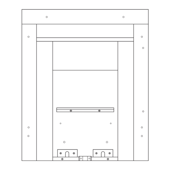
INSTALLATION PROCEDURE FOR STANDARD 22” X 16” OPENING CONTINUED ALTERNATIVE FIXING METHOD Where the drilling of the back panel is not practical, an alternative 112mm 112mm fixing method may be employed using the cable fixing kit provided. Drill four holes in the rear of the fireplace opening (Fig. 5). Securely fix the four eye bolts provided using suitable rawl plugs. -
Page 8: Installation Procedure - Decorative Cast
INSTALLATION PROCEDURE FOR DECORATIVE CAST SURROUND 1. Install the decorative cast surround into the fireplace opening and ensure it is fully sealed including the open area above the fire (see Fig. 7). 2. Carefully lift the fire box out of the packaging taking care not to damage the ceramic components in the separate carton. -
Page 9: Technical Data
TECHNICAL DATA Natural Gas (G20) Cat I 2H LPG (G31) Cat I 3P Gas Type Gas Connection Number of Injectors Injector size Stereomatic 072 Bray 92/150 Control Max Operating Temperature Inlet Pressure Cold 20 mbar (8” W.G.) 37 mbar Heat Input (Gross) 6.9 kW 5.1 kW Weight... -
Page 10: Trouble Shooting (Gas Safe Engineer Only)
TROUBLE SHOOTING (GAS SAFE ENGINEER ONLY) 1. The Piezo will not spark. Check: The battery in the remote handset. The remote control handset generates an infrared signal that will be received by the sensor situated at the front of your fire. The signal requires a direct line of sight from the handset to the fire sensor. -
Page 11: Remote Control Component Layout
REMOTE CONTROL COMPONENT LAYOUT Upper fixing point I.R. sensor Battery pack retainer Battery pack Pilot assembly Heat shield Motorised valve Lower fixing point Control panel Fig. 9 In order to access: a. Pilot Assembly (including thermocouple) b. Motorised Control Valve c. - Page 12 REMOTE CONTROL COMPONENT LAYOUT PILOT SPARK IGNITER/ FLAME SENSOR Fig. 10...
-
Page 13: Test Sequence
TEST SEQUENCE Before starting the test procedure, ensure that the gas is switched on and that the pressure is correct Press the 2 round “ignition” buttons on the handset AT THE SAME TIME Does the Handset light Check/replace batteries come on during operation and re-start test Disconnect batteries and Is there an audible... -
Page 14: Fault Finding Table
FAULT FINDING TABLE Symptom Possible Cause Action No response from remote Low power from handset Replace handset battery handset, no audible beep from battery. the fire - handset indicator light does not illuminate. No response from remote handset, no audible beep from Incorrect handset operation. -
Page 15: User Instructions
USER INSTRUCTIONS THIS APPLIANCE IS INTENDED FOR DECORATIVE PURPOSES. Please also familiarise yourself with the Notes for the Installer and End User on page 4. OPERATION AND CONTROLS It is most important that the operator of this gas appliance has fully read and understood all the operating, cleaning and maintenance procedures as laid out in these instructions. -
Page 16: Cleaning And Maintenance
CLEANING AND MAINTENANCE Cast Tec recommend that this appliance is serviced at regular 12 monthly intervals. The chimney or flue should also be checked regularly to ensure that all products of combustion are entering the flue and there is no excessive build up of soot. -
Page 17: Fire Front Specifications
FIRE FRONT SPECIFICATIONS Fire fronts are now available in many different designs and finishes. The user can now choose their own particular style of fire front to suit their individual fireplace setting, providing the fire front complies with the following dimensions - Fire Front - (X) Max: 210mm Min: 190mm... -
Page 18: Coal Layout Instructions
COAL LAYOUT INSTRUCTIONS - NATURAL GAS & LPG It is very important that all the coals are used and arranged as shown in order to achieve the desired Burner Tray flame picture. It may be necessary to remove some or all of the coals to clean them at some time. - Page 19 COAL LAYOUT INSTRUCTIONS CONTINUED 5. Pick out the smallest two coals and lay to one side, lay the first row of four loose coals on top of the front coal. Ensure the back of the coals are resting on the coal bed and there are even gaps all round (Fig.
-
Page 20: Guarantee
GUARANTEE Your appliance is guaranteed for one year from proof of purchase. Should the appliance prove defective within that period we agree to repair or replace (at our discretion) the component or appliance provided that: 1. The user can produce a receipt for proof of purchase/installation. 2.
Need help?
Do you have a question about the Integra and is the answer not in the manual?
Questions and answers