Table of Contents
Advertisement
Quick Links
Installation guide
RADIO TYBOX
Wireless programmable thermostat
1-zone pack or 2-zone pack
DELTA DORE - Bonnemain
35270 COMBOURG - FRANCE
E-mail: deltadore@deltadore.com
Device compliant with the requirements of directives:
R&TTE 1999/5/CE
Because of changes in standards and equipment, the characteristics
given in the text and the illustrations in this document are not binding
unless confirmed by Delta Dore.
Connecting the receiver
To control electrical convectors, you MUST use a
power contact switch that is suitable for the total power
to be controlled.
N
L
3A
RF 650
3A
Blue
Black
Brown
brown wire
black wire
blue wire
grey wire
L
mains
L
230V
N
supply
N
230V/50Hz
N
N
Power supply
contact switches (not
of the contact
supplied) fitted in the
switch coil
electrical switchboard
convector(s)
convector(s)
Zone 1
Zone 2
The contact outputs of the RF 650 receiver are
powered (phase).
Basic configurations (menu 1)
Press button
1
,
To change the various settings, press the + or -
buttons, then press OK to confirm the change and go
to the next setting.
Weekly (by default)
Choice of
Daily
programming
1-hour increments (by default)
Choice of
30-minute increments
programming
increments
15-minute increments
Warnings
• Carefully read these instructions prior to
installation.
• The unit must be installed in compliance with
currently applicable standards.
• Always switch off the mains before installing or
servicing the unit.
• Do not attempt to repair the unit yourself;
an after-sales service is available.
• The receiver power supply cable must only be
replaced by the manufacturer or an approved
agent.
• Check that the fastenings are suited to the surface
that the unit will be attached to (plasterboard, brick,
etc.).
• The diagrams provided are simplified for greater
clarity. The protective units and other accessories
required by the standards are not illustrated.
Standard UTE NF C15-100 and good practice must
be complied with. Connected or nearby equipment
must not generate excessive interference (directive
2004/108/CE).
receiver Mounting
Screw-mounting
Mounted on a wall using the
screws and pegs supplied.
Mounting by double-sided adhesive tape
If you fit the receiver using adhesive
tape, you must strictly follow the instal-
lation recommendations
(see "location" section).
Ensure that the surface on which the
tape is applied is thoroughly clean
before attaching the tape.
Location / Mounting
For easier use, the RADIO TYBOX can be installed:
- mounted on the wall with screws and pegs at an
approximate height of 1.5 m,
- on a support placed on an item of furniture or a
shelf.
Separate the unit
from its base by
unlocking the
Grey
casing.
Starting up
Remove the bat-
teries' protective
tabs.
Screw-mounting
Mount the base with screws and
pegs suited to the support or on
a flush-mounted box, then close
and lock the unit.
With thermostatic valve electric heating or hot water
heaters, the Comfort temperature can be provided by
adjusting the thermostat of each radiator.
In this case, only Economy and Frost Protection
temperatures are set by the RADIO TYBOX.
Comfort temperature set by the
RADIO TYBOX (by default)
Temperature
Comfort temperature set on each
control Comfort
radiator or convector.
In this option the screen displays ConF.
Anti-seizing off (by default)
Circulator
Anti-seizing enabled (circulator
anti-seizing
operates for 1 minute every
24 hours).
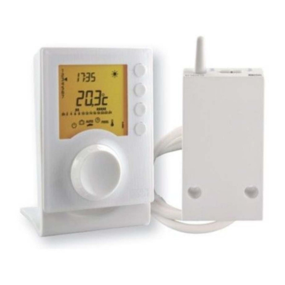
Presentation
The 1-zone pack features a RADIO TYBOX transmitter
associated with an RF 640 receiver (1 zone).
The 2-zone pack features two RADIO TYBOX transmitters
associated with an RF 650 receiver (2 zones).
Zone
Antenna
Antenna
1 LED
LED
1
2
Button
Buttons
RF 640
RF 650
Electric
Electric
cable
cable
The RF 640 and RF 640 can be connected either to a
boiler or to contact switches to control electric heating.
The elements of your system (receiver and
transmitter(s)) are already associated when delivered.
For the 2-zone pack, each transmitter is identified by a
label (EMET 1, EMET 2).
Connecting the receiver
Inverting the relay contact position
During an On command: the relay closes.
During an Off command: the relay opens.
You can invert the operation of the relay by pressing
the relevant button on the receiver for about
10 seconds.
Command sent
Contact
Inverted contact
ON
ON
OFF
OFF
OFF
ON
Connecting a boiler with thermostat input
Connect the black and
N
L
grey wires of the
RF 640
receiver to both
Blue
terminals of the boiler
Brown
thermostat input.
black wire
brown wire
grey wire
blue wire
Mains
N
230V
L
Boiler
thermostat input
Fitting to the base
Position the unit on its base and lock it.
1
2
Position the thermostat
Lock the thermostat
on its base.
Time setting
When you turn the unit on for the first time, you will
need to set the time.
Minutes
Days
Turn the knob to
.
(1 :Monday ...
The days flash.
7 : Sunday)
Press + or - to
change the day, then
Hours
press OK to confirm
and continue on to
the next setting.
Repeat the operations to set the hours and minutes.
To leave the "time setting" mode, turn the knob.
Advanced configurations (menu 2)
2
Press button
.
To change the various settings, press the + or -
buttons, then press OK to confirm the change and go
to the next setting.
Program and temperature settings
(from 5 to 30°C) modification authorized
Modification
authorization
Program and set-point setting
for the user
modification unauthorized
(Comfort: 16 to 22°C,
Economy: 13 to 19°C
Frost Protection: 5 to 11°C)
Location
The receiver must be placed near the heating control
(burner or thermostat input for a boiler, electrical
switchboard when used with a contact switch).
To avoid interference with the radio transmission, the
antenna must be free from any metallic elements
(cables, metallic covers, etc.).
Zone
2 LED
If necessary, remove
Example of a boiler
terminal box
the shunt (electric
wire) connecting the
two thermostat input
terminals.
If the boiler has a
clock input, do not
do not mistake it
for the clock input
mistake it for the
(on some boiler models)
thermostat input.
Connecting a
boiler without
thermostat
RF 640
input
5 A max.
If the boiler does
brown wire
not have a ther-
Black
Grey
mostat input, you
blue wire
can directly control
Mains
N
the circulator loca-
230V
L
ted next to the boi-
ler.
The contact output of the RF 640 receiver is not
powered (dry contact).
Configuration
Turn the knob to
to
access the configuration
i
menus, then press the
button for 5 seconds.
The unit will propose 4 configurations to choose from:
Unit version
Basic configurations (Menu 1)
Advanced configurations (Menu 2)
Configurations of the
consumption indication function
(Menu 3)
Radio association
Unit version
Configuration mode
Menu 3 can only be accessed when the RADIO
TYBOX is associated with a RADIO TYWATT.
Advanced configurations (menu 2)
If there is a difference between the temperature noted (ther-
mometer) and the temperature measured and displayed by
the unit, function 2-02 modifies the way the probe takes mea-
surements so as to compensate for this difference.
Correction possible from -5°C to +5°C
in increments of 0.1°C.
Correction of the
Press the + or - buttons to make changes,
measured
and confirm with the OK button.
temperature.
E.g.
If the temperature dis-
played by the unit is 19°C
and the temperature mea-
sured is 20°C, add 1°C to
the display and confirm by
pressing OK.
Continuous set-point temperature
display (by default)..
With this option, press i to display
Automatic mode
the room temperature.
temperature
display option
Continuous room temperature
display.
With this option, press i to display
the set-point temperature.
Remove
the shunt
wires to be
connected to
the receiver
N
L
5 A max.
Blue
Black
Brown
Grey
black wire
grey wire
Circulator
5 sec.
Advertisement
Table of Contents

Subscribe to Our Youtube Channel
Related Manuals for DELTA DORE Radio Tybox


Summary of Contents for DELTA DORE Radio Tybox
-
Page 1: Installation Guide
Connecting the receiver Location / Mounting Configuration To control electrical convectors, you MUST use a For easier use, the RADIO TYBOX can be installed: Fitting to the base Turn the knob to power contact switch that is suitable for the total power - mounted on the wall with screws and pegs at an Position the unit on its base and lock it. - Page 2 - operation with a TYXAL alarm central control unit, with the RADIO TYBOX control Simultaneously press and hold the buttons Check on the RADIO TYBOX that “1” is no longer - operation with TYXAL or TYDOM remote controls flashing. for 5 seconds, le LED comes on,...
Need help?
Do you have a question about the Radio Tybox and is the answer not in the manual?
Questions and answers