
Related Manuals for EWM Wega 401 FDG


Summary of Contents for EWM Wega 401 FDG
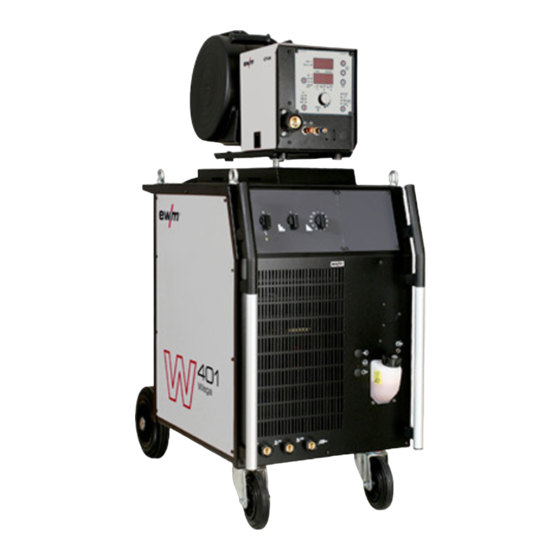
- Page 1 Operating instructions Welding machine Wega 401, 501 FDG Wega 401, 501, 601 FDW 099-004934-EW501 Observe additional system documents! 13.06.2013 Register now! For your benefit Jetzt Registrieren und Profitieren! www.ewm-group.com...
-
Page 2: General Instructions
© EWM HIGHTEC WELDING GmbH · Dr. Günter-Henle-Str. 8 · D-56271 Mündersbach, Germany The copyright to this document remains the property of the manufacturer. -
Page 3: Table Of Contents
Contents Notes on the use of these operating instructions Contents 1 Contents ..............................3 2 Safety instructions ..........................5 Notes on the use of these operating instructions ................5 Explanation of icons ........................6 General ............................7 Transport and installation ......................11 2.4.1 Lifting by crane ...................... - Page 4 7 Rectifying faults............................ 38 Checklist for rectifying faults ......................38 Vent coolant circuit ........................39 8 Technical data............................40 Wega 401 FDG ..........................40 Wega 401 FDW ..........................41 Wega 501 FDG ..........................42 Wega 501, 601 FDW ........................43 9 Accessories ............................
-
Page 5: Safety Instructions
Safety instructions Notes on the use of these operating instructions Safety instructions Notes on the use of these operating instructions DANGER Working or operating procedures which must be closely observed to prevent imminent serious and even fatal injuries. • Safety notes include the "DANGER" keyword in the heading with a general warning symbol. •... -
Page 6: Explanation Of Icons
Safety instructions Explanation of icons Explanation of icons Symbol Description Press Do not press Turn Switch Switch off machine Switch on machine ENTER ENTER (enter the menu) ENTER NAVIGATION NAVIGATION (Navigating in the menu) EXIT EXIT (Exit the menu) Time display (example: wait 4s/press) Interruption in the menu display (other setting options possible) Tool not required/do not use Tool required/use... -
Page 7: General
Safety instructions General General DANGER Electric shock! Welding machines use high voltages which can result in potentially fatal electric shocks and burns on contact. Even low voltages can cause you to get a shock and lead to accidents. • Do not touch any live parts in or on the machine! •... - Page 8 Safety instructions General WARNING Explosion risk! Apparently harmless substances in closed containers may generate excessive pressure when heated. • Move containers with inflammable or explosive liquids away from the working area! • Never heat explosive liquids, dusts or gases by welding or cutting! Smoke and gases! Smoke and gases can lead to breathing difficulties and poisoning.
- Page 9 Safety instructions General CAUTION Obligations of the operator! The respective national directives and laws must be observed for operation of the machine! • National implementation of the framework directive (89/391/EWG), as well as the associated individual directives. • In particular, directive (89/655/EWG), on the minimum regulations for safety and health protection when staff members use equipment during work.
- Page 10 Safety instructions General CAUTION EMC Machine Classification In accordance with IEC 60974-10, welding machines are grouped in two electromagnetic compatibility classes (see technical data): Class A machines are not intended for use in residential areas where the power supply comes from the low-voltage public mains network.
-
Page 11: Transport And Installation
Safety instructions Transport and installation Transport and installation WARNING Incorrect handling of shielding gas cylinders! Incorrect handling of shielding gas cylinders can result in serious and even fatal injury. • Observe the instructions from the gas manufacturer and in any relevant regulations concerning the use of compressed air! •... -
Page 12: Lifting By Crane
Safety instructions Transport and installation 2.4.1 Lifting by crane DANGER Risk of injury during lifting by crane! When lifting the equipment by crane, serious injuries can be inflicted by falling equipment or add-on units. • Transport on all lifting lugs at the same time (see Fig. -
Page 13: Ambient Conditions
Safety instructions Transport and installation 2.4.2 Ambient conditions CAUTION Installation site! The machine must not be operated in the open air and must only be set up and operated on a suitable, stable and level base! • The operator must ensure that the ground is non-slip and level, and provide sufficient lighting for the place of work. -
Page 14: Intended Use
Intended use Applications Intended use WARNING Hazards due to improper usage! Hazards may arise for persons, animals and material objects if the equipment is not used correctly. No liability is accepted for any damages arising from improper usage! • The equipment must only be used in line with proper usage and by trained or expert staff! •... -
Page 15: Documents Which Also Apply
Intended use Documents which also apply Documents which also apply 3.3.1 Warranty NOTE For further information, please see the accompanying supplementary sheets "Machine and Company Data, Maintenance and Testing, Warranty"! 3.3.2 Declaration of Conformity The designated machine conforms to EC Directives and standards in terms of its design and construction: •... -
Page 16: Machine Description - Quick Overview
Machine description – quick overview Wega 401 Machine description – quick overview Wega 401 NOTE Coolant tank and quick connect coupling of coolant supply and return are only fitted in machines with water cooling. 4.1.1 Front view Figure 4-1 099-004934-EW501 13.06.2013... - Page 17 Machine description – quick overview Wega 401 Item Symbol Description Lifting lug Main switch, machine on/off Welding voltage step switch, presetting To roughly preset the welding voltage Welding voltage step switch, final setting To finally adjust the welding voltage (select the option to roughly preset the welding voltage first) Signal light, Functional error On when excess temperature detected...
-
Page 18: Rear View
Machine description – quick overview Wega 401 4.1.2 Rear view Figure 4-2 099-004934-EW501 13.06.2013... - Page 19 Machine description – quick overview Wega 401 Item Symbol Description Intermediate hose package strain relief Key button, automatic cutout Wire feed motor supply voltage fuse press to reset a triggered fuse 7-pole connection socket Wire feed unit control lead Mains connection cable Button, Automatic cut-out of fan motor Press to reset tripped circuit breaker Quick connect coupling (red)
-
Page 20: Wega 501, 601
Machine description – quick overview Wega 501, 601 Wega 501, 601 NOTE Coolant tank and quick connect coupling of coolant supply and return are only fitted in machines with water cooling. 4.2.1 Front view Figure 4-3 099-004934-EW501 13.06.2013... - Page 21 Machine description – quick overview Wega 501, 601 Item Symbol Description Lifting lug Carrying handle Main switch, machine on/off Ready for operation signal light Signal light on when the machine is switched on and ready for operation Signal light, Functional error On when excess temperature detected Welding voltage step switch, presetting To roughly preset the welding voltage...
-
Page 22: Rear View
Machine description – quick overview Wega 501, 601 4.2.2 Rear view Figure 4-4 099-004934-EW501 13.06.2013... - Page 23 Machine description – quick overview Wega 501, 601 Item Symbol Description Key button, automatic cutout Wire feed motor supply voltage fuse press to reset a triggered fuse Automatic cut-out of coolant pump key button press to reset a triggered fuse Button, Automatic cut-out of fan motor Press to reset tripped circuit breaker Mains connection cable...
-
Page 24: Design And Function
Design and function General Design and function General WARNING Risk of injury from electric shock! Contact with live parts, e.g. welding current sockets, is potentially fatal! • Follow safety instructions on the opening pages of the operating instructions. • Commissioning may only be carried out by persons who have the relevant expertise of working with arc welding machines! •... -
Page 25: Installation
Design and function Installation CAUTION Damage due to incorrect connection! Accessory components and the power source itself can be damaged by incorrect connection! • Only insert and lock accessory components into the relevant connection socket when the machine is switched off. •... -
Page 26: Welding Torch Cooling System
Design and function Welding torch cooling system Welding torch cooling system 5.5.1 General CAUTION Coolant mixtures! Mixtures with other liquids or the use of unsuitable coolants result in material damage and renders the manufacturer's warranty void! • Only use the coolant described in this manual (overview of coolants). •... -
Page 27: Adding Coolant
Design and function Welding torch cooling system 5.5.3 Adding coolant The unit is supplied ex works with a minimum level of coolant. Figure 5-1 Item Symbol Description Coolant tank cap Coolant filter sieve Coolant tank "Min" mark Minimum coolant level •... -
Page 28: Mains Connection
Design and function Mains connection Mains connection DANGER Hazard caused by improper mains connection! An improper mains connection can cause injuries or damage property! • Only use machine with a plug socket that has a correctly fitted protective conductor. • If a mains plug must be fitted, this may only be carried out by an electrician in accordance with the relevant national provisions or regulations! •... -
Page 29: Intermediate Hose Package Connection
Design and function Intermediate hose package connection Intermediate hose package connection 5.7.1 Wega 401 Figure 5-3 Item Symbol Description Wire feed unit Intermediate hose package Intermediate hose package strain relief 7-pole connection socket Wire feed unit control lead Earth cable connecting (PE) Connection of green-yellow earth cable from the intermediate tube package Connector plug, welding current "+"... -
Page 30: Wega 501, 601
Design and function Intermediate hose package connection 5.7.2 Wega 501, 601 Figure 5-4 Item Symbol Description Wire feed unit Intermediate hose package Intermediate hose package strain relief 7-pole connection socket Wire feed unit control lead Earth cable connecting (PE) Connection of green-yellow earth cable from the intermediate tube package Connector plug, welding current "+"... -
Page 31: Shielding Gas Supply (Shielding Gas Cylinder For Welding Machine)
Design and function Shielding gas supply (shielding gas cylinder for welding machine) Shielding gas supply (shielding gas cylinder for welding machine) WARNING Risk of injury due to improper handling of shielding gas cylinders! Improper handling and insufficient securing of shielding gas cylinders can cause serious injuries! •... -
Page 32: Connection
Design and function Shielding gas supply (shielding gas cylinder for welding machine) 5.8.1 Connection Figure 5-5 Item Symbol Description Pressure regulator Shielding gas cylinder Output side of the pressure regulator Cylinder valve • Place the shielding gas cylinder into the relevant cylinder bracket. •... -
Page 33: Connection For Workpiece Lead
Design and function Connection for workpiece lead Connection for workpiece lead 5.9.1 Wega 401 Figure 5-6 Item Symbol Description Workpiece Workpiece lead Connection socket, workpiece lead "Medium" choke tapping Connection socket, workpiece lead Choke tapping "soft" Connection socket, workpiece lead "Hard"... -
Page 34: Wega 501, 601
Design and function Connection for workpiece lead 5.9.2 Wega 501, 601 Figure 5-7 Item Symbol Description Workpiece Workpiece lead Connection socket, workpiece lead "Hard" choke tapping Connection socket, workpiece lead "Medium" choke tapping Connection socket, workpiece lead Choke tapping "soft" •... -
Page 35: Maintenance, Care And Disposal
Maintenance, care and disposal General Maintenance, care and disposal DANGER Risk of injury from electric shock! Cleaning machines that are not disconnected from the mains can lead to serious injuries! • Disconnect the machine completely from the mains. • Remove the mains plug! •... -
Page 36: Monthly Maintenance Tasks
Maintenance, care and disposal Maintenance work 6.2.2 Monthly maintenance tasks 6.2.2.1 Visual inspection • Casing damage (front, rear and side walls) • Wheels and their securing elements • Transport elements (strap, lifting lugs, handle) • Check coolant tubes and their connections for impurities 6.2.2.2 Functional test •... -
Page 37: Disposing Of Equipment
Information about giving back used equipment or about collections can be obtained from the respective municipal administration office. • EWM participates in an approved waste disposal and recycling system and is registered in the Used Electrical Equipment Register (EAR) under number WEEE DE 57686922. •... -
Page 38: Rectifying Faults
Rectifying faults Checklist for rectifying faults Rectifying faults All products are subject to rigorous production checks and final checks. If, despite this, something fails to work at any time, please check the product using the following flowchart. If none of the fault rectification procedures described leads to the correct functioning of the product, please inform your authorised dealer. -
Page 39: Vent Coolant Circuit
Rectifying faults Vent coolant circuit Vent coolant circuit NOTE Coolant tank and quick connect coupling of coolant supply and return are only fitted in machines with water cooling. To vent the cooling system always use the blue coolant connection, which is located as deep as possible inside the system (close to the coolant tank)! Figure 7-1 099-004934-EW501... -
Page 40: Technical Data
Technical data Wega 401 FDG Technical data NOTE Performance specifications and guarantee only in connection with original spare and replacement parts! Wega 401 FDG Switching steps 24 (2 x 12) Setting range for welding current 30 A to 400 A Setting range for welding voltage 15.5 V to 34.0 V... -
Page 41: Wega 401 Fdw
Technical data Wega 401 FDW Wega 401 FDW Switching steps 24 (2 x 12) Setting range for welding current 30 A to 400 A Setting range for welding voltage 15.5 V to 34.0 V Duty cycle at 25 °C ambient temperature 400 A 100% 300 A... -
Page 42: Wega 501 Fdg
Technical data Wega 501 FDG Wega 501 FDG Switching steps 36 (3 x 12) Setting range for welding current 50 A to 500 A Setting range for welding voltage 16.5 V–39.0 V Duty cycle at 40 °C ambient temperature 500 A 100% 400 A Duty cycle at 25 °C ambient temperature... -
Page 43: Wega 501, 601 Fdw
Technical data Wega 501, 601 FDW Wega 501, 601 FDW 501 DW 601 DW Switching steps 36 (3 x 12) Setting range for welding current 50 A to 500 A 50 A to 600 A Setting range for welding voltage 16.5 V–39.0 V 16.5 V–44.0 V Duty cycle at 40 °C ambient temperature... -
Page 44: Accessories
Accessories System components Accessories NOTE Performance-dependent accessories like torches, workpiece leads, electrode holders or intermediate hose packages are available from your authorised dealer. System components Type Designation Item no. Wega M1.02 drive 41 Wire feed unit, water, Euro central connector 090-004962-00502 Wega M1.02 drive 41L Wire feed unit, water, Euro central connector... -
Page 45: Options
Accessories Options Options 9.3.1 Wega 401 Type Designation Item no. ON DK drive 41 Wega 401 Pivot support, horizontal for drive 41 092-002522-00000 ON DK drive 41L Wega Pivot support, horizontal for drive 41L 092-002113-00000 ON Filter W Retrofit option contamination filter for air inlet 092-002091-00000 ON Holder Gas Bottle <50L Holding plate for gas cylinders smaller than 50 litres 092-002151-00000... -
Page 46: Setting Instructions
Appendix A Setting instructions Appendix A 10.1 Setting instructions Figure 10-1 099-004934-EW501 13.06.2013... - Page 47 Appendix A Setting instructions Figure 10-2 099-004934-EW501 13.06.2013...
- Page 48 Appendix A Setting instructions Figure 10-3 099-004934-EW501 13.06.2013...
-
Page 49: Overview Of Ewm Branches
Appendix B Overview of EWM branches Appendix B 11.1 Overview of EWM branches 099-004934-EW501 13.06.2013...
Need help?
Do you have a question about the Wega 401 FDG and is the answer not in the manual?
Questions and answers