Table of Contents
Advertisement
Available languages
Available languages
Quick Links
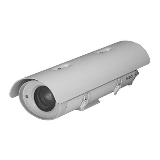
HSG9583 Series
Instruction Manual
EN Environmental
Enclosures
Manuel d'utilisation
FR
Caractéristiques
environnementales
Bedienungshandbuch
DE Außenanwendungen
Manual de instrucciones
ES Carcasas
Medioambientales
Instructiehandleiding
NL
Omgevingsombouw
Manuale utente
IT
Custodie di protezione
Manual de Instruções
PT
Caixa de Protecção
Exterior
Advertisement
Chapters
Table of Contents

Related Manuals for Bosch HSG9583 Series


Summary of Contents for Bosch HSG9583 Series
- Page 1 HSG9583 Series Instruction Manual EN Environmental Enclosures Manuel d’utilisation Caractéristiques environnementales Bedienungshandbuch DE Außenanwendungen Manual de instrucciones ES Carcasas Medioambientales Instructiehandleiding Omgevingsombouw Manuale utente Custodie di protezione Manual de Instruções Caixa de Protecção Exterior...
-
Page 2: Important Safeguards
EN | 2 HSG9583 Series | Instruction Manual | Important Safeguards Important Safeguards 1. Read, Follow, and Retain Instructions - All safety 10. Power Sources - Operate the unit only from the type and operating instructions should be read and of power source indicated on the label. -
Page 3: Safety Precautions
EN | 3 HSG9583 Series | Instruction Manual | Safety Precautions Safety Precautions For Indoor Product 1. Water and Moisture - Do not use this unit near water - for example, in a wet basement, in an unprotected outdoor installation, or in any area classified as a wet location. -
Page 4: Table Of Contents
EN | 4 HSG9583 Series | Instruction Manual | Table of Contents Table of Contents Important Safeguards ..............2 UNPACKING . -
Page 5: Unpacking
If an item appears to have been damaged in shipment, UNPACKING replace it properly in its carton and notify the shipper. This electronic equipment should be unpacked and If any items are missing, notify your Bosch Security handled carefully. Systems, Inc. Sales Representative or Customer Service •... -
Page 6: Installation
EN | 6 HSG9583 Series | Instruction Manual | Installation Input Power Cord - European INSTALLATION Cable Type: H05RN-F 3 G 0.75 and CAUTION: These units must be properly H05RN-F 3 G 1.00 and securely mounted to a supporting Cable Size:... -
Page 7: Camera/Lens Installation
EN | 7 HSG9583 Series | Instruction Manual | Installation For installations of zoom lens cameras: Camera/Lens Installation Attach the lens to the camera. Remove the two screws holding the camera tray to the housing. Remove tray from the Use the various 1/4-20 screws and housing. - Page 8 EN | 8 HSG9583 Series | Instruction Manual | Installation Feed-through Wiring Install one of the large 1/2in. NPT fittings into one of the holes in the rear Use feed-through mounts to feed cabling cap. If using the feed-through option, through the foot of the housing.
-
Page 9: Video Coax Connection
EN | 9 HSG9583 Series | Instruction Manual | Installation Pull any excess wire out of the housing Video Coax Connection and tighten the fitting to 8.5 . N . m to See SECTION 5 for HSG9583/22, HSG9583/52, and 9.0 N . m (75in . lb to 80in . lb). This torque HSG9583/53 Models. -
Page 10: Lens Wiring
EN | 10 HSG9583 Series | Instruction Manual | Installation Optional tamper-resistant screws are provided Lens Wiring with the housing. If desired, secure the latch WARNING: For lens wiring, use only the using these two screws and the provided cables specified under INSTALLATION, tamper-resistant wrench. -
Page 11: Hsg9583/22, Hsg9583/52, Hsg9583/53 Models
EN | 11 HSG9583 Series | Instruction Manual | HSG9583/22,/52,/53 Connect the power input cable to the screw HSG9583/22, HSG9583/52, terminals on the provided mating connector and HSG9583/53 MODELS (see FIGURE 9 and Wiring Diagram for pin Camera/Lens Wiring connections). -
Page 12: Operation
EN | 12 HSG9583 Series | Instruction Manual | Operation OPERATION SERVICE PARTS These housings require no operational adjustments Description Part No. other than camera/lens adjustments. Spacer, 4mm, ABS 77018-00 Spacer, 9mm, ABS 77019-00 MAINTENANCE Screw, Tamper-resistant 77029-00 No special maintenance is required other than Wrench, Tamper-resistant 87017-00 occasional cleaning of the window. -
Page 13: Exploded View
EN | 13 HSG9583 Series | Instruction Manual | Exploded View EXPLODED VIEW Part # Description Part # Description 36001-00 Front Assembly for all models 35722-00 115VAC Heater (HSG9583/61) 35741-00 Sunshield Kit for all models 35723-00 220VAC Heater Kit (HSG9583/50/51/52/53) - Page 14 EN | 14 HSG9583 Series | Instruction Manual | Bosch Security Systems | 12 August 2005...
-
Page 15: Consignes De Sécurité Importantes
Cette opération permet d'éviter les dégâts au d'origine. L'utilisation de pièces non homologuées niveau de l'appareil en cas d'orage ou de surtension présente un risque d'incendie, d'électrocution et des lignes électriques. d'autres dangers. Bosch Security Systems | 12 August 2005... - Page 16 2. Chargement mécanique - Le montage de l'appareil en bâti doit être exempt de tout risque d'accident lié à un chargement mécanique irrégulier. Bosch Security Systems | 12 August 2005...
- Page 17 VUE ÉCLATÉE ............. . .13 Bosch Security Systems | 12 August 2005...
-
Page 18: Déballage
Avec chauffage et ventilateur, si applicable. Les systèmes de chauffage et de ventilation de tous les modèles nécessitent une alimentation 50/60 Hz. Ces modèles disposent d’un connecteur à 4 broches et d’un connecteur BNC au lieu de presse-étoupes. Bosch Security Systems | 12 August 2005... -
Page 19: Installation
Sources : Belden 19509, 3 conducteurs REMARQUE : Si les vis inviolables optionnelles ont Northwire FSJT183-81K, 3 conducteurs été installées, utilisez la clé fournie pour retirer les vis avant d’ouvrir les attaches de fermeture. Bosch Security Systems | 12 August 2005... -
Page 20: Installation De La Caméra/De L'objectif
Si vous utilisez un enduit d’étanchéité, assurez-vous que celui-ci est de type neutre de vulcanisation. Les enduits d’étanchéité produisant de l’acide acétique peuvent endommager les circuits électroniques de la caméra. Bosch Security Systems | 12 August 2005... - Page 21 Assurez-vous que les trous pratiqués dans le capot arrière sont bien obturés par les bouchons de caoutchouc fournis. Enfoncez-les jusqu’à ce qu’ils affleurent contre la paroi du caisson, et relâchez- les ensuite. Bosch Security Systems | 12 August 2005...
- Page 22 5. Écrou 3. Rondelle plate 2. Cosse de fil de terre interne 1. Cosse de fil de terre externe Fondre Le Poteau Symbole de terre Figure 7 : Mise à la terre de sécurité Bosch Security Systems | 12 August 2005...
-
Page 23: Connexion Vidéo Coaxiale
Câblage de l’objectif AVERTISSEMENT : Pour le câblage de l’objectif, utilisez uniquement le câblage spécifié dans la section INSTALLATION, Câblage requis. Installez la dernière fixation NPT 3/8” dans le dernier trou du capot arrière. Bosch Security Systems | 12 August 2005... -
Page 24: Réglage De La Caméra/De L'objectif
2 A, 250 Vca à votre guise la mise au point et l’objectif de la 115 Vca 1 A, 250 Vca caméra. Reportez-vous aux instructions 230 Vca 500 mA, 250 Vca d’utilisation de la caméra. Bosch Security Systems | 12 August 2005... -
Page 25: Modèles Hsg9583/22, Hsg9583/52 Et Hsg9583/53
Joint d’étanchéité 24 Vca Logement arrière Dispositif de UNIQUEMENT ! réduction de Bague tension interne d’entraînement Rondelle métallique mâle 230 Vca UNIQUEMENT ! Femelle Figure 9 : Montage du connecteur à 4 broches Bosch Security Systems | 12 August 2005... -
Page 26: Fonctionnement
Capuchon, passage inférieur 87048-00 Ces caissons ne nécessitent aucune opération de réglage autre que le réglage de la caméra et de l’objectif. MAINTENANCE Hormis le nettoyage occasionnel de la vitre, aucune maintenance spéciale n’est nécessaire. Bosch Security Systems | 12 August 2005... -
Page 27: Vue Éclatée
Kit de chauffage 24 Vca (HSG9583/20/21/22) 77013-00 Support pour HSG9583/00/20/21/50/51/61 35722-00 Kit de chauffage 115 Vca (HSG9583/61) 77078-00 Support for HSG9583/22/52/53 Figure 10 : Vue éclatée et liste des pièces du caisson HSG9583 Bosch Security Systems | 12 August 2005... - Page 28 FR | 14 Série HSG9583 | Manuel d’utilisation | Bosch Security Systems | 12 August 2005...
- Page 29 Gewitters oder wenn es über einen längeren Zeitraum nicht verwendet wird, indem Sie den Stecker aus der Steckdose ziehen und die Verbindung zum Kabelsystem trennen. So kann das Gerät nicht durch einen Blitzeinschlag oder Überspannung beschädigt werden. Bosch Security Systems | 12 August 2005...
- Page 30 Die maximale Betriebstemperatur für dieses Gerät sollte nicht überschritten werden. 2. Mechanische Belastung - Beim Aufbau des Geräts in einem Rack ist auf mögliche Gefahren durch ungleiche mechanische Belastung zu achten. Bosch Security Systems | 12 August 2005...
- Page 31 EXPLOSIONSDARSTELLUNG ..........12 Bosch Security Systems | 12 August 2005...
-
Page 32: Auspacken
Heizelem. = Heizelement; Gebl. = Gebläse; SB = Sonnenblende Hinweise: Mit Heizelement und Gebläse, sofern zutreffend. Heizelemente und Gebläse für alle Modelle für Betrieb bei 50/60 Hz. Diese Modelle verfügen über einen 4-poligen Anschluss und einen BNC-Anschluss anstelle von Durchführungshalterungen. Bosch Security Systems | 12 August 2005... -
Page 33: Installation
4,3 mm - 11,9 mm Kabelform: Rund Leiter: 3-adrig und 2-adrig Sicherheitsprüfung: UL/C.S.A., UL VW-1 Verwendung: Außeneinsatz Temperaturbereich: 105° C Spannung: 300 V Quelle: Belden 19509, 3-adrig Abbildung 1: Entriegeln der Abdeckung Northwire FSJT183-81K, 3-adrig Bosch Security Systems | 12 August 2005... -
Page 34: Installation Der Kamera Und Des Objektivs
Schieben Sie das gesamte Gerät nach vorne gelangen und die Kamera und das Objektiv bis ca. 5 mm vor die Scheibe. Ziehen Sie beschädigen. die Schrauben in den dafür vorgesehenen Löchern an (siehe Abbildung 4). Bosch Security Systems | 12 August 2005... - Page 35 Anschlussdose geführt werden, falls er Falls Sie die Halterung nicht fest genug nicht durch die Halterung verläuft. anziehen, führt dies zu Wassereintritt und Beschädigung aller elektronischen Teile. d. Montieren Sie den Befestigungsfuß an der oberen Gehäusehalterung. Bosch Security Systems | 12 August 2005...
- Page 36 Gehäuse, und ziehen Sie die Halterung mit einem Drehmoment von 8,5 Nm bis 9,0 Nm fest. Dieses Drehmoment entspricht etwa 1 bis 1-1/2 Drehungen nach dem Punkt, an dem die Halterung am Draht zu greifen beginnt. Bosch Security Systems | 12 August 2005...
-
Page 37: Videokoaxverbindung
4.10 Endmontage angegebenen Kabel. Verschließen Sie alle ungenutzten Öffnungen in der hinteren Abdeckung mit den mitgelieferten Montieren Sie die letzte 3/8 Zoll-NPT- Schutzkappen. Halterung in das letzte freie Loch in der hinteren Abdeckung. Bosch Security Systems | 12 August 2005... -
Page 38: Sonnenblende
(siehe Abbildung 9 sowie den Schaltplan für Verbindungsstifte). Kameraspannung Sicherungsnennwert 24 V AC 2 A, 250 V AC 115 V AC 1 A, 250 V AC 230 V AC 500 mA, 250 V AC Bosch Security Systems | 12 August 2005... -
Page 39: Bedienung
Kamera an. Klemmring Kabelmutter Dichtung Nur 24 V Rückwärtiges Gehäuse Wechselstrom! Interne Zugentlastungs- klemme Gewindering Unterlegscheibe aus Metall mit Stecker Nur 230 V Wechselstrom! Buchse Abbildung 9: Montage des 4-poligen Anschlusssteckers Bosch Security Systems | 12 August 2005... -
Page 40: Explosionsdarstellung
Heizkombination für 24 V AC (HSG9583/20/21/22) 77013-00 Befestigungsfuß für 35722-00 Heizelement für 115 V AC (HSG9583/61) HSG9583/00/20/21/50/51/61 35723-00 Heizkombination für 220 V AC 77078-00 Befestigungsfuß für HSG9583/22/52/53 (HSG9583/50/51/52/53) Abbildung 10: Explosionsdarstellung und Teileliste für HSG9583 Bosch Security Systems | 12 August 2005... - Page 41 óptimas de funcionamiento. Bosch Security Systems | 12 August 2005...
-
Page 42: Precauciones De Seguridad
2. Carga mecánica - el montaje del equipo en un soporte se debe realizar de tal manera que no se cree una situación de peligro debido a una carga mecánica inestable. Bosch Security Systems | 12 August 2005... - Page 43 VISTA DETALLADA ............13 Bosch Security Systems | 12 August 2005...
-
Page 44: Desembalaje
El equipo electrónico debe desembalarse y manejarse notifique al transportista. Si falta algún elemento, con cuidado. comuníquelo al representante de ventas local de Bosch • Compruebe que se han incluido los siguientes Security Systems, Inc. o al representante de servicio al elementos para el modelo que ha adquirido. -
Page 45: Instalación
Índice de agencia: UL/C.S.A., UL VW-1 panorámica/inclinación. Especificaciones medioambientales: Diseñado para exteriores Índice de temperatura: 105°C Intervalo de tensión: 300 V Fuentes: Belden 19509, de 3 conductores Northwire FSJT183-81K, de 3 conductores Bosch Security Systems | 12 August 2005... -
Page 46: Apertura De La Cubierta
Separadores combinados Separador de 9 mm para 13 mm Separador de 4 mm Tornillos y arandelas 1/4 pulg. 5/8 pulg. planas Figura 2: Separadores Figura 5: Acoplamiento de la cámara con lente Zoom Bosch Security Systems | 12 August 2005... -
Page 47: Cableado De La Cámara/Lente
De no realizarse así, el agua podría dañar todos componentes electrónicos. Acople el soporte a la parte superior del montaje. Bosch Security Systems | 12 August 2005... - Page 48 Figura 7: toma de tierra de seguridad tamaño de cable inferior en el extremo del bloque terminal. Si el empalme no pasa a través de los racores, puede ser necesario introducirlo en una caja de empalmes. Bosch Security Systems | 12 August 2005...
-
Page 49: Conexión Coaxial De Vídeo
Si utiliza sellador, asegúrese de que sea de tipo neutro. Los selladores que liberan ácido acético pueden dañar los componentes electrónicos de la cámara. Se recomienda el uso de bucles de goteo en el cableado exterior de la cubierta posterior. Bosch Security Systems | 12 August 2005... -
Page 50: Cableado De La Lente
5 x 20 mm y acción lenta. Voltaje de la cámara Intervalo del fusible 24 VCA 2 A, 250 VCA 115 VCA 1 A, 250 VCA 230 VCA 500 mA, 250 VCA Bosch Security Systems | 12 August 2005... -
Page 51: Modelos Hsg9583/22, Hsg9583/52, Hsg9583/53
Tuerca de cable Junta selladora SÓLO 24 Cubierta posterior Pieza de alivio de presión Anillo interna Arandela metálica acoplador macho SÓLO 230 VCA Hembra Figura 9: Ensamblaje de 4 patillas de conector de acoplamiento Bosch Security Systems | 12 August 2005... -
Page 52: Conexión Coaxial De Vídeo
Conector perforado, alimentación inferior 87048-00 FUNCIONAMIENTO Estas carcasas no requieren ajustes de funcionamiento distintos de los ajustes de la cámara/lente. MANTENIMIENTO No se requiere ningún mantenimiento especial distinto de la limpieza esporádica de la ventana. Bosch Security Systems | 12 August 2005... -
Page 53: Vista Detallada
77013-00 Soporte para HSG9583/00/20/21/50/51/61 35721-00 Kit de calentador de 24 VCA (HSG9583/20/21/22) 77078-00 Soporte para HSG9583/22/52/53 35722-00 Calentador de 115 VCA (HSG9583/61) Figura 10: Vista detallada y lista de piezas del modelo HSG9583 Bosch Security Systems | 12 August 2005... - Page 54 ES | 14 Serie HSG9583 | Manual de instrucciones | Bosch Security Systems | 12 August 2005...
- Page 55 Niet erkende onderdelen netsnoer uit het stopcontact te halen en alle overige kabels kunnen aanleiding geven tot brand, elektrische schokken los te koppelen. Zo voorkomt u bliksemschade en schade of andere gevaren. veroorzaakt door stroomstoten. Bosch Security Systems | 12 August 2005...
- Page 56 De apparatuur mag de maximale vereisten voor de bedrijfstemperatuur niet overschrijden. 2. Mechanische belasting - Wanneer de apparatuur in een rek wordt geplaatst, moet de mechanische belasting gelijk worden verdeeld om gevaarlijke situaties te vermijden. Bosch Security Systems | 12 August 2005...
- Page 57 VERGROTE WEERGAVE ............12 Bosch Security Systems | 12 August 2005...
-
Page 58: Uitpakken
• Controleer of de volgende onderdelen voor het Bosch Security Systems, Inc. De unit kan het beste betreffende model aanwezig zijn. worden vervoerd in het verpakkingsmateriaal. Bewaar •... -
Page 59: Montage
OPMERKING: Als de optionele sabotageschroeven Spanningswaarde: 300 V zijn gebruikt, moet u deze schroeven Bronnen: Belden 19509, 3 geleiders eerst met de bijgeleverde sleutel Northwire FSJT183-81K, 3 geleiders verwijderen voordat u de grendels opent. Bosch Security Systems | 12 August 2005... -
Page 60: Montage Van Camera En Lens
De gaten zijn geschikt voor NPT-doorlaatfittingen van 3/8 inch of 1/2 inch. Niet-gebruikte gaten moeten worden afgedekt met de afdekdopjes die Afbeelding 4: Lade met camera en lens in de sleuf bij de behuizing worden geleverd. schuiven Bosch Security Systems | 12 August 2005... - Page 61 Aanbevolen kabellengten voor behuizingen met aangesloten en als laatste worden verwijderd. camera’s van 24 volt, verwarmingen en ventilatoren. Dikte van draad Afstand behuizing meter (voet) 27 (90) 42 (140) 67 (220) 108 (355) 172 (565) Bosch Security Systems | 12 August 2005...
-
Page 62: Aansluiting Van De Videocoaxkabel
Bedrading van de lens WAARSCHUWING: Voor het bedraden van lenzen mogen alleen de kabels uit het kabelschema in MONTAGE worden gebruikt. Bosch Security Systems | 12 August 2005... -
Page 63: Afstelling Van Camera En Lens
De zekering is een trage, cartridge-achtige zekering van 5 x 20 mm. Voeding camera Zekering 24 VAC 2 A, 250 VAC 115 VAC 1 A, 250 VAC 230 VAC 500 mA, 250 VAC Bosch Security Systems | 12 August 2005... -
Page 64: Modellen Hsg9583/22, Hsg9583/52, Hsg9583/53
(zie AFBEELDING 9). Klemring Kabelmoer Pakking ALLEEN Achterste koker 24 VAC! Interne trekontlasting Koppelring Metalen ringetje mannelijk ALLEEN 230 VAC! Vrouwelijk Afbeelding 9: In elkaar zetten van de bijbehorende, 4-polige connector Bosch Security Systems | 12 August 2005... -
Page 65: Aansluiting Van De Videocoaxkabel
Afdekdopje voor schroefgat, Buiten het reinigen van het venster hoeft er geen NPT van 3/8 inch 77072-00 speciaal onderhoud te worden uitgevoerd. Afdekdopje voor schroefgat, NPT van 1/2 inch 77071-00 Afdekdopje voor schroefgat, onderkant 87048-00 Bosch Security Systems | 12 August 2005... -
Page 66: Vergrote Weergave
Kit met beugel voor camera en lens (lade) (zonder VNR) 77013-00 Voet voor HSG9583/00/20/21/50/51/61 35721-00 Kit met 24 VAC verwarming HSG9583/20/21/22) 77078-00 Voet voor HSG9583/22/52/53 Afbeelding 10: Vergrote weergave en onderdelenlijst van HSG9583 Bosch Security Systems | 12 August 2005... - Page 67 Bosch Security Systems | 12 August 2005...
- Page 68 2. Carico meccanico - Il montaggio dell'apparecchiatura in un rack deve essere effettuato in modo tale da impedire che si venga a creare una condizione di rischio dovuta a una distribuzione non uniforme del carico meccanico. Bosch Security Systems | 12 August 2005...
- Page 69 VISTA ESPLOSA ............. .12 Bosch Security Systems | 12 August 2005...
-
Page 70: Disimballaggio
• Verificare che i seguenti componenti siano clienti Bosch Security Systems, Inc. La scatola di inclusi nella confezione per il modello ordinato. imballaggio è il contenitore più sicuro in cui l’unità può essere trasportata. Conservarla per eventuali •... -
Page 71: Installazione
Figura 1: Sbloccaggio del coperchio Fonti: Belden 19509 a 3 conduttori Northwire FSJT183-81K a 3 conduttori NOTA: Se sono state installate le viti antimanomissione opzionali, utilizzare la chiave fornita per rimuoverle prima di aprire i fermi. Bosch Security Systems | 12 August 2005... -
Page 72: Installazione Della Telecamera/Ottica
Sostegno non ostegno installato installato Condotto correttamente correttament nello slot Queste custodie sono progettate per consentire e nello slot un collegamento diretto del condotto. Figura 4: Inserimento del sostegno della telecamera/ottica nello slot Bosch Security Systems | 12 August 2005... - Page 73 2. Capocorda della terra interna Per le telecamere a 24 volt, utilizzare lo schema 3. Rondella piatta Massime lunghezze di cavo consigliate per scegliere le dimensioni del cavo appropriate. 4. Rondella di blocco 5. Dado Bosch Security Systems | 12 August 2005...
-
Page 74: Collegamento Video Coassiale
Si raccomanda l’utilizzo di uno sgocciolatoio per il cablaggio all’esterno del cappuccio terminale posteriore. Bosch Security Systems | 12 August 2005... -
Page 75: Cablaggio Dell'ottica
Verificare il funzionamento della telecamera e 230 V CA 500 mA, 250 V CA dell’ottica prima dell’assemblaggio finale. Regolare la messa a fuoco e il diaframma della telecamera. Vedere le istruzioni della telecamera. Bosch Security Systems | 12 August 2005... -
Page 76: Modelli Hsg9583/22, Hsg9583/52, Hsg9583/53
Dado del cavo Guarnizione a tenuta SOLO Cilindro cavo posteriore 24 V CA! Serracavo Innesto interno maschio ad Rondella di metallo anello SOLO 230 V CA! Femmina Figura 9: Assemblaggio del connettore a 4 pin Bosch Security Systems | 12 August 2005... -
Page 77: Funzionamento
Tappo, alimentazione inferiore 87048-00 Per il funzionamento di tali custodie non sono necessarie altre regolazioni oltre a quelle della telecamera/ottica. MANUTENZIONE Non è necessaria una manutenzione speciale oltre alla occasionale pulizia della finestra. Bosch Security Systems | 12 August 2005... -
Page 78: Vista Esplosa
Kit riscaldatore da 24 V CA (HSG9583/20/21/22) 77013-00 Piede per HSG9583/00/20/21/50/51/61 35722-00 Riscaldatore da 115 V CA (HSG9583/61) 77078-00 Piede per HSG9583/22/52/53 35723-00 Kit riscaldatore da 220 V CA (HSG9583/50/51/52/53) Figura 10: Vista esplosa ed elenco parti di 0 Bosch Security Systems | 12 August 2005... - Page 79 Assim, evitará danos na unidade devido a relâmpagos e picos estado de funcionamento. de corrente eléctrica. Bosch Security Systems | 12 August 2005...
- Page 80 O equipamento não pode exceder os requisitos máximos da temperatura de funcionamento. 2. Carregamento mecânico - A montagem do equipamento numa prateleira deve ser feita de modo a evitar os perigos derivados de um carregamento mecânico incerto. Bosch Security Systems | 12 August 2005...
- Page 81 VISTA PORMENORIZADA ........... . .12 Bosch Security Systems | 12 August 2005...
-
Page 82: Desembalagem
Se faltar algum elemento, notifique o Representante de DESEMBALAGEM Vendas ou o Representante da Assistência ao Cliente Este equipamento electrónico deve ser desembalado e local da Bosch Security Systems, Inc. O cartão de manuseado cuidadosamente. envio é a embalagem mais segura na qual a unidade •... -
Page 83: Instalação
HSG9583 Series | Instruction Manual | Installation PT | 5 Cabo de alimentação de entrada - Europeu INSTALAÇÃO Tipo de cabo: H05RN-F 3 G 0,75 e ATENÇÃO: Estas unidades têm de ser H05RN-F 3 G 1,00 montadas de uma forma segura e adequada Secção do cabo:... -
Page 84: Instalação Da Câmara/Objectiva
NPT de 3/8pol ou 1/2pol. Quaisquer orifícios não utilizados têm de ser cobertos com Figura 4: Deslize do tabuleiro da câmara/objectiva para os tampões fornecidos com a caixa. a ranhura Bosch Security Systems | 12 August 2005... - Page 85 Comprimentos máximos recomendados dos cabos ligação a ser estabelecida, e a última ligação para Caixas equipados com ventiladores, aquecedores e câmaras de 24 volts. a ser removida. Tamanho do fio Distância da caixa metros Bosch Security Systems | 12 August 2005...
-
Page 86: Ligação Coaxial Do Vídeo
24VCA, 115VCA ou 230VCA, dependendo do modelo de caixa. Pino 2 está ligado a fusíveis internos e deve ser ligado ao lado com tensão da corrente eléctrica para os modelos de 115VCA e 230VCA. Bosch Security Systems | 12 August 2005... -
Page 87: Fios Da Objectiva
O fusível é um fusível de tipo cartucho de fusão lenta de 5 x 20mm. Tensão da câmara Classificação dos fusíveis 24VCA 2A, 250VCA 115VCA 1A, 250VCA 230VCA 500mA, 250VCA Bosch Security Systems | 12 August 2005... -
Page 88: Modelos Hsg9583/22, Hsg9583/52, Hsg9583/53
(consulte a FIGURA 9). Anel de fixação Porca do cabo Junta vedante APENAS Casquilho posterior 24VCA! Abraçadeira interna União Anilha metálica Anel macho APENAS 230VCA! Fêmea Figura 9: Conjunto do conector acoplado de 4 pinos Bosch Security Systems | 12 August 2005... -
Page 89: Funcionamento
Tampão, NPT de 3/8pol 77072-00 Tampão, NPT de 1/2pol 77071-00 FUNCIONAMENTO Tampão, alimentação inferior 87048-00 Estas caixas só requerem os ajustes operacionais da câmara/objectiva. MANUTENÇÃO Não é necessária manutenção especial, excepto a limpeza ocasional da janela. Bosch Security Systems | 12 August 2005... -
Page 90: Vista Pormenorizada
KIt do aquecedor de 24VCA (HSG9583/20/21/22) 15 77078-00 Pé para HSG9583/22/52/53 35722-00 Kit do aquecedor de 115VCA (HSG9583/61) 35723-00 Kit do aquecedor de 220VCA (HSG9583/50/51/52/53) Figura 10: Lista de peças e vista pormenorizada do HSG9583 Bosch Security Systems | 12 August 2005... - Page 91 PT | 13 Série HSG9583 | Manual de Instrução | Bosch Security Systems | 12 August 2005...
- Page 92 The Netherlands Republic of Singapore Fax: 1-717-735-6560 Tele +31 40 27 80000 Tel: 65 (6) 319 3486 www.boschsecuritysystems.com © 2004 Bosch Security Systems GmbH 3122 165 23321 04-15 | Updated August 12, 2005 | Data subject to change without notice.
Need help?
Do you have a question about the HSG9583 Series and is the answer not in the manual?
Questions and answers