Sign In
Upload
Download
Table of Contents
Contents
Add to my manuals
Delete from my manuals
Share
URL of this page:
HTML Link:
Bookmark this page
Add
Manual will be automatically added to "My Manuals"
Print this page
×
Bookmark added
×
Added to my manuals
Manuals
Brands
Bosch Manuals
Camera Accessories
VGA-PEND-ARM
Installation manual
Bosch VGA-PEND-ARM Installation Manual
Autodome pendant arm mount
Hide thumbs
1
2
Table Of Contents
3
4
5
6
7
8
9
10
11
12
13
14
15
16
17
18
19
20
21
22
23
24
25
26
27
28
29
30
31
32
33
34
35
36
page
of
36
Go
/
36
Contents
Table of Contents
Bookmarks
Table of Contents
Table of Contents
1 Important Safety Instructions
Safety Precautions
Important Notices
UL Certification
Bosch Notices
2 Installing the Pendant Arm Wall, Corner, and Mast (Pole) Mounts
Unpacking
Parts List
Optional Mounting Accessories
Optional Power Supplies
Description
Tools Required
Pre-Installation Checklist
Pressurized Environmental Mounting Options
Route Wires
Coaxial Cable Connections
Installing the VGA-PEND-ARM
Attach the Pendant Arm to the Mounting Plate
Route and Connect Wires to a Power Supply Box
Attach Pendant to Arm and Tighten
3 Cable and Wire Standards
Power
Wire Distance Guide for Pendant
Video and Control Cables
Using Coaxial Cable to Transmit Video and Control
Using UTP to Transmit Video and Control
Using Ethernet to Transmit Video and Control
Using Multi-Mode Fiber Optic to Transmit Video and Control
Using a Fiber Optic Ethernet Media Converter to Transmit Video and Control
Control-Only Cables
Controlling the Autodome Via Biphase
Controlling the Autodome Via the RS232 Protocol
Controlling the Autodome Via the RS485 Protocol
Fiber Optic Module with an RS232/RS422 Controller
Connecting to an LTC 4629 Head End Data/Video Transceiver
Configuring the VG5 Autodome
Audio Cables
4 Alarms and Relay Connections
Alarm Inputs
Configuring Supervised Alarms (Inputs 1 and 2)
Configuring a Normally Open Supervised Alarm
Configuring a Normally Closed Supervised Alarm
Advertisement
Quick Links
Download this manual
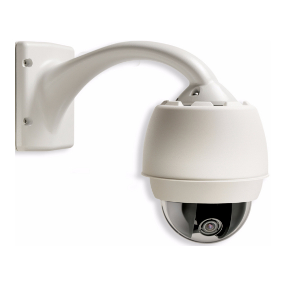
AutoDome Pendant Arm Mount
VGA-PEND-ARM | VGA-PEND-WPLATE
en
Installation Guide
Available from A1 Security Cameras
www.a1securitycameras.com email: sales@a1securitycameras.com
Table of
Contents
Previous
Page
Next
Page
1
2
3
4
5
Advertisement
Table of Contents
Need help?
Do you have a question about the VGA-PEND-ARM and is the answer not in the manual?
Ask a question
Questions and answers
Related Manuals for Bosch VGA-PEND-ARM
Camera Accessories Bosch VDA-PLEN-DOME Installation Manual
Flexidome in-ceiling housing for plenums (8 pages)
Camera Accessories Bosch VJR-A3-IC54 Installation Instructions Manual
Ip-54 in-ceiling mount (20 pages)
Camera Accessories Bosch VGA-PEND-WPLATE Installation Manual
Autodome pendant arm mount (36 pages)
Camera Accessories Bosch VEZ-A4-IC Installation Manual
Mini ptz dome accessories vez-400 in-ceiling mount (15 pages)
Camera Accessories Bosch Professional GBA 36 V 6.0Ah Hw-D Original Instructions Manual
(158 pages)
Camera Accessories Bosch PowerPack 400 Owner's Manual
Drive system battery (20 pages)
Camera Accessories Bosch PowerPack 300 Original Instructions Manual
Active line/performance line (71 pages)
Camera Accessories Bosch BC630 Operating And Safety Instructions Manual
(20 pages)
Camera Accessories Bosch UPH-C485N-L8120 Specifications
High‑speed positioning system (10 pages)
Camera Accessories Bosch PowerTube 750 Series Battery Manual
Lithium-ion batteries (19 pages)
Camera Accessories Bosch UHO-HBPS Installation Manual
Uho camera housing (24 pages)
Camera Accessories Bosch PowerTube 500 Operating Instructions Manual
(80 pages)
Camera Accessories Bosch PowerPack 300 Original Operating Instructions
(85 pages)
Camera Accessories Bosch PowerMore 250 Operating Instructions Manual
(82 pages)
Camera Accessories Bosch UHI-SBG-0 Installation Manual
Indoor housing (110 pages)
Camera Accessories Bosch PowerMore 250 Owner's Manual
(50 pages)
This manual is also suitable for:
Vga-pend-wplate
Table of Contents
Print
Rename the bookmark
Delete bookmark?
Delete from my manuals?
Login
Sign In
OR
Sign in with Facebook
Sign in with Google
Upload manual
Upload from disk
Upload from URL


Need help?
Do you have a question about the VGA-PEND-ARM and is the answer not in the manual?
Questions and answers