Table of Contents
Advertisement
Quick Links
Advertisement
Table of Contents

Related Manuals for Elation E Spot Led II


Summary of Contents for Elation E Spot Led II
- Page 1 E SPOT LED II™ user manual 1.0 ...
- Page 2 ©2013 ELATION PROFESSIONAL all rights reserved. Information, specifications, diagrams, images, and instructions herein are subject to change without notice. ELATION PROFESSIONAL logo and ...
-
Page 3: Table Of Contents
w w w . e l a t i o n l i g h t i n g . c o m C O N T E N T S General Information Warranty Safety Instructions General Guidelines Fixture Overview Installation Understanding DMX... -
Page 4: General Information
Congratulations, you have just purchased one of the most innovative and reliable lighting ™ fixtures on the market today! The E SPOT LED II has been designed to perform reliably for years when the guidelines in this booklet are followed. Please read and understand the instructions in this manual carefully and thoroughly before attempting to operate this unit. - Page 5 You may also visit us on the web at www.elationlighting.com for any comments or suggestions. For service related issue please contact Elation Professional®. Service Hours are Monday through Friday 8:00 a.m. to 5:00 p.m. PST. Voice: 323-582-3322 Fax: 323-832-9142 E-mail: support@elationlighting.com...
-
Page 6: Warranty
B. For warranty service, send the product only to the Elation Professional® factory. All shipping charges must be pre-paid. If the requested repairs or service (including parts replacement) are within the terms of this warranty, Elation Professional®... -
Page 7: Safety Instructions
S A F E T Y I N S T R U C T I O N S ™ The E SPOT LED II is an extremely sophisticated piece of electronic equipment. To guarantee a smooth operation, it is important to follow the guidelines in this manual. -
Page 8: General Guidelines
w w w . e l a t i o n l i g h t i n g . c o m G E N E R A L G U I D E L I N E S •... -
Page 9: Fixture Overview
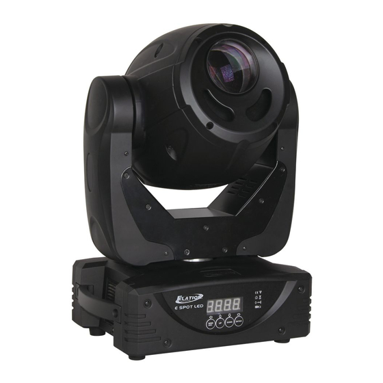
w w w . e l a t i o n l i g h t i n g . c o m F I X T U R E O V E R V I E W LED Assembly LCD Menu Function Display Mode/Esc Button... -
Page 10: Installation
w w w . e l a t i o n l i g h t i n g . c o m I N S T A L L A T I O N T he el ec tri c c onnec ti on m ust onl y b e c arri ed out b y a qu al if i ed el ec tri c i an. C A U T I O N S •... - Page 11 CLAMP MOUNTING ™ The E SPOT LED II provides a unique mounting bracket assembly that integrates the bottom of the base, the included “Omega Bracket,” and the safety cable rigging point in one unit (see the illustration below).
- Page 12 . e l a t i o n l i g h t i n g . c o m SECURING ™ Regardless of the rigging option you choose for your E SPOT LED II always be sure to secure your fixture with a safety cable. The fixture provides a built-in rigging point for a safety cable on the hanging bracket as illustrated above.
-
Page 13: Understanding Dmx
The DMX controller knows to send data assigned to address 1 to that fixture no matter where it is located in the DMX chain. The E SPOT LED II™ can be controlled via DMX-512 protocol and the DMX address is set via the control menu. - Page 14 Connect the provided XLR cable to the female XLR output of your controller and the other side to the male XLR input of the E SPOT LED II™ The diagram below illustrates a typical DMX-512 connection when the fixture is in the 14 Channel Extended Mode. You can chain multiple panels together through serial linking.
- Page 15 w w w . e l a t i o n l i g h t i n g . c o m DMX-512 CONNECTION WITH DMX TERMINATOR A DMX terminator should be used in all DMX lines especially in longer runs. The use of a terminator may avoid erratic behavior in your DMX line.
- Page 16 That means changing the settings of one channel will only affect the selected fixture. In the case of the E SPOT LED II™, when in the 14 Channel Extended Mode (default can also be set to 12 Channel Standard Mode), you should set the starting DMX address of the first unit to 1, the second unit to 15 (14 + 1), the third unit to 29 (14 + 15), and so on.
-
Page 17: Fixture Menu
F I X T U R E M E N U ON-BOARD SYSTEM MENU The E SPOT LED II™ comes with an easy to navigate system menu. The next section will detail the functions of each command in the system menu. - Page 18 E SPOT LED II™ S YSTEM M ENU ...
- Page 19 DMX signal the display will flash continuously. To set or adjust a DMX address, please follow the procedure below: 1. Switch on the E SPOT LED II™ and wait for the fixture reset process to finished. 2. Press MODE/ESC to access the main menu. Toggle through the menu by pressing UP and DOWN until the display shows A001.
- Page 20 w w w . e l a t i o n l i g h t i n g . c o m 2. PLAY MENU This feature is used to run the internal preset programs in either a Master/Slave or a Stand-Alone operating mode.
- Page 21 w w w . e l a t i o n l i g h t i n g . c o m AUTO Runs the unit without any DMX signal in Stand-Alone mode. 1. Access the main menu. 2.
- Page 22 w w w . e l a t i o n l i g h t i n g . c o m SCAN When you activate this reset function, only the PAN and TILT motors are reset. 1.
- Page 23 w w w . e l a t i o n l i g h t i n g . c o m 4. TIME MENU LIFE - Displays the fixtures total running time. CLMP - Clears the lamp running time. LIFE With this function you can display the total running time of the fixture.
- Page 24 w w w . e l a t i o n l i g h t i n g . c o m 6. RTLT MENU This menu function will reverse the mirror TILT movements. 1. Access the main menu. 2.
- Page 25 w w w . e l a t i o n l i g h t i n g . c o m 8. DEGR MENU This menu function changes the maximum amount of PAN movement from either or 540 .
- Page 26 w w w . e l a t i o n l i g h t i n g . c o m VALU This function will display the DMX value of a channel as a DMX control console changes it.
- Page 27 w w w . e l a t i o n l i g h t i n g . c o m LOCK This function allows you to lock the keys on the display to prevent menu tampering.
- Page 28 w w w . e l a t i o n l i g h t i n g . c o m SPOT This function allows you to optimize the lamp without the use of an external DMX controller.
- Page 29 w w w . e l a t i o n l i g h t i n g . c o m FEED Use this function to activate the PAN/TILT error correction. 1. Access the main menu. 2.
- Page 30 w w w . e l a t i o n l i g h t i n g . c o m Use this function to display the Software version of the unit. 1. Access the main menu. 2.
- Page 31 w w w . e l a t i o n l i g h t i n g . c o m 12. EDIT MENU This menu item allows you to write a program into the fixture’s internal memory (EEPROM) via the control panel or via an external DMX controller.
-
Page 32: Dmx Addressing
w w w . e l a t i o n l i g h t i n g . c o m DMX ADDRESSING Setting the DMX Address - After the fixture is turned “ON” it will immediately complete a reset process that tests all the fixture’s functions. - Page 33 w w w . e l a t i o n l i g h t i n g . c o m Controller Settings: 1. Set the DMX value of Channel 1 to a value of 7. 2.
- Page 34 . e l a t i o n l i g h t i n g . c o m Operation Operating Modes: The E SPOT LED II™ can operate in six different modes. This next section will detail the differences in the operating modes.
- Page 35 A DMX controller allows you to create unique programs tailored to your individual needs. The E SPOT LED II™ uses 14 (default) DMX channels. See page 39 for detailed description of the DMX traits. To control your fixture in DMX mode, follow the set-up procedures on pages 13-16 as well as the set-up specifications that are included with your DMX controller.
- Page 36 w w w . e l a t i o n l i g h t i n g . c o m WORKING WITH BUILT-IN PROGRAMS The fixture comes equipped with a built-in DMX recorder that allows custom programs to be installed and recalled directly from the fixture’s control board.
- Page 37 w w w . e l a t i o n l i g h t i n g . c o m “Auto Program” – Allows access to all 14 of the fixture’s DMX traits. “PAN” – pan movement. “PAN-Fine”...
- Page 38 w w w . e l a t i o n l i g h t i n g . c o m Step 2 – Editing Programs. The control will store a maximum of 10 programs. A program can store one or a maximum of 64 scenes.
-
Page 39: Dmx Channel Functions And Values
w w w . e l a t i o n l i g h t i n g . c o m D M X C H A N N E L F U N C T I O N S A N D V A L U E S E ... - Page 40 w w w . e l a t i o n l i g h t i n g . c o m E S POT L ED I I 40 U ser ...
- Page 41 w w w . e l a t i o n l i g h t i n g . c o m E S POT L ED I I 41 U ser ...
-
Page 42: Error Codes
w w w . e l a t i o n l i g h t i n g . c o m E R R O R C O D E S When power is applied, the unit will automatically enter a “Reset/Test” mode. This mode brings all the internal motors to a home position. - Page 43 w w w . e l a t i o n l i g h t i n g . c o m Color-Wheel Error: The color wheel is not located in the default position after start-up or after a reset command. This message will appear after a fixture reset if the color wheel’s magnetic-indexing circuit malfunctions (sensor failed or magnet is missing) or there is a stepper motor failure (defective motor or a defective motor IC drive on the main PCB).
-
Page 44: Cleaning And Maintenance
Regular inspections are recommended to insure proper function and an extended life. There are no user serviceable parts inside this fixture, please refer all other service issues to an authorized Elation service technician. Should you need any spare parts, please order genuine parts from your local Elation dealer. -
Page 45: Technical Specifications
w w w . e l a t i o n l i g h t i n g . c o m T E C H N I C A L S P E C I F I C A T I O N S FEATURES Greater Output and 1/2 the Power of 150W Discharge 16bit Pan and Tilt Motors... -
Page 46: Photometric Data
w w w . e l a t i o n l i g h t i n g . c o m PHOTOMETRIC DATA FULL ON 944 FC / 10,160 LUX 245 FC / 2636 LUX 107 FC / 1157 LUX LUX x 0.0929 = FC 2.5 m 8.2 ft... -
Page 47: Dimensional Drawings
w w w . e l a t i o n l i g h t i n g . c o m DIMENSIONAL DRAWINGS 11.4” (290mm) 9.6” 7.9” (243mm) (200mm) 8.1” (206mm) 9.5” (241mm) 16.0” (407mm) 3.3” (84mm) 4.3”... - Page 48 w w w . e l a t i o n l i g h t i n g . c o m CIRCUIT SCHEMATICS Please Note: Specifications and improvements in the design of this unit and this manual are subject to change without any prior written notice. E ...
-
Page 49: Optional Accessories
w w w . e l a t i o n l i g h t i n g . c o m OPTIONAL ACCESSORIES ORDER CODE ITEM TRIGGER CLAMP Heavy Duty Wrap Around Hook Style Clamp AC3PDMX5PRO 5 ft. -
Page 50: Declaration Of Conformity
w w w . e l a t i o n l i g h t i n g . c o m E S POT L ED I I 50 U ser ...
Need help?
Do you have a question about the E Spot Led II and is the answer not in the manual?
Questions and answers