Table of Contents
Advertisement
Advertisement
Table of Contents

Related Manuals for Gericom SuperSonic Extrem HD P55IM1


Summary of Contents for Gericom SuperSonic Extrem HD P55IM1
- Page 3 Preface © Copyright 2007 © All Rights Reserved. The information in this document is subject to change without prior notice in order to improve reliability, design and function and does not represent a commitment on the part of the manufacturer. In no event will the manufacturer be liable for direct, indirect, special, incidental, or consequential damages arising out of the use or inability to use the product or documentation, even if...
- Page 4 • Reorient or relocate the receiving antenna • Increase the separation between the equipment and receiver • Connect the equipment into an outlet on a circuit different from that to which the receiver is connected Consult the dealer or an experienced radio TV technician for help This device complies with Part 15 of the FCC Rules.
-
Page 5: Table Of Contents
Table of Content 1. B ................1 EFORE YOU TART ..........8 ET YOUR COMPUTER ACCLIMATE ITSELF ............8 UMIDITY LARE ..............9 UITABLE PLACE TO WORK 2. I ..................11 NTRODUCTION LCD P ..............11 PENING THE ANEL ..................12 RONT ..................14 ..................14 IGHT IEWS ..................15 IEWS ...................16 OTTOM... - Page 6 ............33 ULTIMEDIA OUND YSTEM ..............34 UDIO OLUME ONTROL ................34 UDIO OFTWARE ................34 OUND ECORDING ..............34 LAYING OUND ILES ...........34 XTERNAL PEAKERS AND ICROPHONE 6. I ..............35 NTERNET ONNECTION 7. R BIOS S ..............39 UNNING ETUP ....................40 ..................41 ETUP ................41 DVANCED ETUP ..................42 ECURITY...
- Page 7 ...............60 HE FILES ARE CORRUPTED ..........60 HE OPTICAL DRIVE DOES NOT WORK ..........60 HE DRIVE DOSE NOT READ ANY DISKS ............60 HE DISK CANNOT BE EJECTED DVD RW ......60 OMBO OR DRIVE CANNOT RECORD ..61 HE DISPLAY PANEL IS BLANK WHEN THE SYSTEM IS TURNED ON - ..........61 HE SCREEN IS DIFFICULT TO READ - ..............61...
-
Page 9: Before You Start
Conventions of This Manual Use this manual will help you get the most from your notebook computer. • If you are an experienced user of computers and/or Microsoft’s Windows operating systems, you might find it useful to read the Quick Start Guide that comes along with your accessories. •... - Page 10 Please disconnect this equipment from AC outlet before cleaning. Don't use liquid or sprayed detergent for cleaning. Use moisture sheet or cloth for cleaning. For pluggable equipment, that the socket-outlet shall be installed near the equipment and shall be easily accessible. Please keep this equipment from humidity.
- Page 11 selection. The cord set must be approved for the country in which it is used. The appliance coupler must have a configuration for mating with a CEE22/EN6032/IEC 320 appliance inlet. For U.S. and Canada: The cord set must be UL Listed and CSA Certified.
- Page 12 Do not use the telephone to report a gas leak in the vicinity of the leak. Use only the power cord indicated in this manual. 19. Do not use the AC adapter near open water or other liquids. Never spill liquid into the AC adapter. 20.
- Page 13 23. Note to CATV System Installer – This reminder provided to call the CATV system installer’s attention to Section 820-93 of the National Electric Code which provide guidelines for proper grounding and in particular, specify that the Coaxial cable shield shall be connected to the grounding system of the building, as close to the point of cable entry as practical This part is hot.
- Page 14 Servicepersonal geöffnet werden. 13. Wenn folgende Situationen auftreten ist das Gerät vom Stromnetz zu trennen und von einer qualifizierten Servicestelle zu Überprüfung.: . Netzlabel oder Netzstecker sind beschädigt. . Flüssigkeit ist in das Gerät eingedrungen. . Das Gerät war Feuchtigkeit ausgesetzt. .
- Page 15 Alle Teile des Kabel-Sets müssen entsprechend dem japanischen Dentori Law mit einem „PSE“ or „T”-Symbol markiert sein Die Minimalanforderungen für das Kabel sind .75m ㎡ Leiter. Für andere Länder: Die Zubehörteile des Kabel-Sets müssen das Prüfsiegel derjenigen Stelle, die in dem jeweiligen Land für die Sicherheitsprüfung zuständig ist, tragen.
-
Page 16: Let Your Computer Acclimate Itself
Entsorgen Sie Akkus entsprechend den Anweisungen des Herstellers. Entfernen Sie den Akku auf keinen Fall bei eingeschaltetem Notebook, da hierdurch Daten verloren gehen könnten. 22. Der Netzeingabeanschluss dient als Hauptschalter des Geräts. 23. Hinweis für die CATV-Systeminstallation: Dieser Hinweis dient dazu, die Aufmerksamkeit der CATV-Systemmonteure auf Abschnitt 820-93 des National Electrical Code zu richten, der Richtlinien für die korrekte Erdung enthält und im Besonderen... -
Page 17: Suitable Place To Work
Suitable place to work Your computer will run well wherever you’re comfortable but extremes of temperature and humidity can be challenging to your system’s parts. There are some things you can tolerate that the computer can’t – things like static electricity, dust, water, steam and oil. In case you decide to pull over for roadside computing, try to choose a clean, comfortable work area for your system. -
Page 19: Introduction
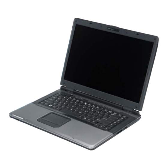
Welcome to the Notebook PC Congratulations on your purchase of the Notebook PC. Your Notebook features the latest advances in portable computing technology. The Notebook’s modular design provides maximum expandability without compromising portability. Getting to Know Your Computer Opening the LCD Panel To avoid damage to the display panel: 1. -
Page 20: Front View
Front View Do not place any heavy objects on the top of notebook. This may damage the display 1. LCD Latch 2. CCD Camera 3. LCD Display Music Button Mute Button 6. Power Button 7. Keyboard 8. Touchpad 9. LED Status Indicator... - Page 21 System & Power Status Indicators Indication Symbol Blue light indicates the touchpad is disabled. Blue light indicates the WLAN module is active. Persistent Blue light indicates the Suspend Mode is enabled. Blinking orange light indicates the battery is being charged. Blinking red light indicates the battery power is low when the system is turned ON.
-
Page 22: Left View
Left View 1. Microphone/Audio Line-in Jack 2. Stereo Headphone/SPDIF-out Jack 3. ExpressCard (New Card) Slot 4. Optical Drive Right Views 1. 5-in-1 Card Reader (SD/MMC/MS/MS Pro/XD) 2. USB2.0 Port... -
Page 23: Rear Views
Rear Views 1. Kensington Lock 2. Ventilation Opening 3. External CRT Port 4. S-Video output Port 5. HDMI Port 6. Power Jack (DC-in) 7. 1394 Port 8. Modem Port Always disconnect all telephone lines from the wall outlet before servicing or disassembling this equipment. -
Page 24: Bottom View
Bottom View 1. Battery Release Latch 2. Battery Compartment 3. Hard Disk Drive... -
Page 25: Started
Connecting to a Power Source Connecting the AC Adapter A universal AC adapter is provided to supply your computer with power and also charge the computer’s battery pack. The adapter’s AC input voltage can range anywhere from 100 to 240 volts, covering the standard voltages available in almost every country. - Page 26 Notebook and an electrical outlet to recharge the battery. Never turn off or reset your Notebook while the hard disk is in use and the CD-ROM status icon is lit; doing so can result in loss or destruction of your data.
-
Page 27: To Remove The Battery Pack
Danger of explosion if battery is incorrectly replaced. Replace only with same or equivalent type recommended by the manufacturer. Discard used batteries according to the manufacturer’s instructions or local laws. Explisionsgefahr bei unsachgernazen Austausch der Batterie. Ersatz nur durch denselben oder einem Hersteller empfohlenem... - Page 28 Charging the Battery Pack The installed battery pack charges automatically any time the computer is connected to the AC adapter and an external power source. It is a good idea to occasionally discharge the battery pack fully to preserve its operating performance.
-
Page 29: Using The Notebook Computer
Adjusting the LCD Screen Display The LCD screen display can be adjusted by the following key combinations. KEYS FUNCTIONS Fn + F9 Increases the brightness level. Fn + F8 Decreases the brightness level. Fn + F10 Changes Display Mode: LCD-only, CRT-only and LCD&CRT. -
Page 30: Function Keys (Quick Keys)
You can switch between these display configurations by pressing the key combination [Fn] + [F10]. For information on connecting an external display, please refer to Chapter Four. The Notebook’s Hot Key Controls Function Keys (Quick Keys) Action System Control Fn + F3 Mute the system. -
Page 31: Precautions For Handling Cd Discs
• The Audio Play feature allows you to play music CDs • Front panel load/unload button • Supports CD-DA, CD-ROM mode 1 and mode 2, Multi-Session Photo CD™, CD-I/Video CD (pcs.) • Low power consumption • 12.7mm height Precautions for Handling CD Discs •... -
Page 32: The Battery Power System
The CD disk tray should eject immediately. This procedure can also be used to remove a CD from the drive when the Notebook is powered off. Power Saving Modes This section contains information on the Notebook’s power system, including the AC Adapter, the battery system, recharging the battery, and tips for conserving battery power. -
Page 33: Preparing The Battery Pack For Use (Battery Calibration)
Preparing the Battery Pack for Use (Battery Calibration) Before using the battery pack for the first time, the Smart Battery IC within the battery pack should be calibrated in order to get accurate reporting of remaining battery life status. To calibrate the battery pack follows the instructions below: Insert the battery into the battery compartment and turn on the Notebook. -
Page 34: Battery Status
Battery Status Windows Vista has an applet in the Control Panel that will display an icon in the Windows taskbar indicating when the Notebook is running on battery power or is attached to the AC adapter. This applet also displays a meter that indicates how much charge is remaining in the battery. - Page 35 If the Notebook is left without a power source for long period of time, this battery will be exhausted and system information will be lost. Danger of explosion if battery is incorrectly replaced. Replace only with the same or equivalent type recommended by the manufacturer.
-
Page 36: Help Windows
Using the Windows Help Windows For Windows Vista help, click Start Help and Support icon will open the dialog box. Desktop Desktop may vary differently on the software installed in your notebook with different or additional shortcuts. - Page 37 Recycle Bin Used for storing deleted files in case you want to recover and save it in your system. The files will only be deleted from the Recycle Bin permanently only if you empty it by right clicking your mouse and select the “Empty Recycle Bin”.
- Page 38 Notification The icons that appear here are for quick access to some programs and computer functions that you frequently used. For you to see the hidden icons, simply click the icon. To prevent Windows Vista from hiding icons: From an empty spot on the Taskbar, right click your mouse and select the Properties, remove the checked mark on the Hide inactive icons.
- Page 39 Control Panel It is in this area that you can change how Windows looks and works. Click Start Control Panel dialog box. There are two interfaces – Classic View.
-
Page 41: Desktop Operation
Your notebook is capable of providing you with efficient and productive mobile computing, it also has the speed and capacity to service as a desktop system. This chapter discusses those functions of your notebook that are typical of desktop systems. Audio The Multimedia Sound System The Notebook’s built-in audio capabilities allow you to take... -
Page 42: Audio Volume Control
Audio Volume Control The Notebook is equipped with hot-key volume controls: Pressing the [Fn]+[F4] hot-key combination decreases the audio output volume, press the [Fn]+[F5] hot-key combination increases the audio output volume. Audio Software Your notebook comes equipped with an integrated sound system capable of providing you with quality audio sound through the built- in speakers or through external speakers connected via the system ports. -
Page 43: Internet Connection
There are numerous ways to connect to the Internet. This may vary from the user’s working environment as well as system specifications. • Using a modem and a telephone line (Optional) • Using a wired LAN • Using a wireless LAN Using a modem for Connection to Internet (Optional) •... - Page 44 Using a wired LAN for Connection to Internet For you connect to the Internet, a wired LAN environment normally uses the company’s LAN or a broadband modem.
- Page 45 Using Wireless LAN Network for Connection to Internet Bluetooth Connection (Optional) Bluetooth is a developing, world wide, open, short-range radio specification focused on communication between the Internet and Net devices, plus it defines communication protocols between devices and computers. It connect wirelessly to your world: In home, at work, in motion and at play.
- Page 46 This will be the display that will appear on your screen. If the system detects any other devices, it will be shown this way:...
-
Page 47: Running Bios Setup
The Setup Utility is a hardware configuration program built into your computer’s BIOS (Basic Input/Output System). It runs and maintains a variety of hardware functions. It is menu-driven software, which allows you to easily configure and change the settings. The BIOS contains manufacture’s default settings for the computer’s standard operations. -
Page 48: Info
BIOS Action Keys Function Command Description Leaves a sub-menu to return to the Exit previous menu OR exits the BIOS setup while saving changes. Enter Go to Sub Screen Shows the Sub Menu General Help Shows the Help Screen Setup Default Load default configuration Save and Exit Saves changes and reboots the computer. -
Page 49: Main Setup
Main Setup Under this menu, you may change time/date and view basic processor and system memory information. Advanced Setup... -
Page 50: Security
Security Power... -
Page 51: Boot Setup
Boot Setup Exit Setup... -
Page 53: Vga Utilities
You can also click the touchpad or mouse right button and select the “ATI CATALYST® Control Center” item. -
Page 54: Display Manager
Display Manager This feature allows you to connect external display devices. -
Page 55: Display Options
Display Options... -
Page 56: Notebook Panel Properties
Notebook Panel Properties... -
Page 57: Color
Color... -
Page 58: Video
Video... -
Page 60: Powerplay
PowerPlay... -
Page 61: Video Conferencing (Optional )
This application offers video conferencing capabilities to work and communicate in real-time with one or more participants through streaming video, from any location. Web Camera Application Press the “Camera” icon or “Fn + F7” key to display the “Web Camera” screen display. Your image will immediately display on the small screen. -
Page 62: Snapshot Command
Using Commands and Buttons Snapshot Command Click on the “Snapshot” button to capture the present picture that appear in the “Camera Assistant Software Lite” window. Record Command Click on the “Record” button to capture the video played in the “Camera Assistant Software Lite” window. -
Page 63: Property Command
Property Command Press on the “Property” icon to display the “Property” settings window. This dialog box has the following scroll bars and buttons for controlling the color components of the video image. -
Page 64: Setting Command
Setting Command Press on the “Setting” icon to display the “Property” properties window. This dialog box has the following scroll bars for selecting the default video format, color space, output size. -
Page 65: Troubleshooting
Your computer has been fully tested and complies with the system specifications before shipping. However, incorrect operations and/or mishandling may cause problems. This chapter provides a reference for identifying and correcting common hardware and software problems that you may encounter. When you encounter a problem, you should first try to go through the recommendations in this chapter. -
Page 66: No Speaker Output
• Be sure all the device drivers are installed properly. For example, without the audio driver properly installed, the speakers and microphone will not work. • If external devices such as USB camera, scanner, printer do not function correctly when connected to the system, it is usually the device’s own problem. -
Page 67: The Hard Disk Drive Does Not Work Or Is Not Recognizable
After Click OK button, the recording volume control panel will appear. • Go to [Start > Settings > Control Panel] and double-click the Multimedia icon (or Sounds and Audio Devices icon). In the Volume or Audio page, make sure that Realtek AC97 Audio is the default recording device. -
Page 68: The Hard Disk Takes Longer To Read A File
The hard disk takes longer to read a file • If you have been using the drive for a period, the files may be fragmented. Go to [Start > Programs > Accessories > System Tools > Disk Defragmenter] to perform a disk defragmentation. This operation may take a while. -
Page 69: The Display Panel Is Blank When The System Is Turned On
Display Problems The display panel is blank when the system is turned on • Make sure the computer is not in the Standby or Hibernate suspend modes. The display is turned off to conserve energy in these modes. The screen is difficult to read - •... -
Page 70: A Message "Cmos Checksum Failure" Displays During The Booting Process Or The Time (Clock) Resets When Booting
box shows up with the adjustable settings for the keyboard. CMOS Battery Problem A message “CMOS Checksum Failure” displays during the booting process or the time (clock) resets when booting • Try to reboot the system. • If the message “CMOS Checksum Failure” appears during the booting procedure even after rebooting, it may indicate failure of the CMOS battery. -
Page 71: The Pc Card Cannot Be Recognized
• Consult the card’s manual or contact the vendor for trouble- shooting. The PC card cannot be recognized - • Windows NT4.0 does not support PCMCIA (PC Card) function. You may need an external program for this. • Make sure the card is fully inserted; the outer end of the card should be even with the edge of the computer. -
Page 72: The Usb Device Does Not Work
system is accessing slow-speed devices such the floppy disk drive. • You may be running too many applications. Try to close some applications or increase system memory for higher performance. • The processor may have been overheated due to the system’s inability to regulate its internal heat. -
Page 73: Specification
Operating System • Supports Windows Vista Premium • Linux Knoppix bootable • Merom For Santa Rosa dual core processor, T7800, FSB 800 MHz, L2 cache 4MB, TDP 35W • Celeron M / TJ85 CPU Memory • Supports dual channels DDR2 memory interface. •... - Page 74 IEEE 1394 • Support IEEE 1394 and 1394a with Open HCI Compliance • PCI V2.2 MAC/BIU supports TV-Encoder • Display on a PAL or NTSC TV • Support for Macrovision 7.1 copy protection standard-a fully programmable timing capability LAN Controller •...
- Page 75 Optical Device • DVD Dual (Double Layer) and BluRay and HD DVD support • GBAS support • Support PATA interface only Card reader Controller • Support SD/MMC/MS/MS Pro/XD Memory Card • USB 2.0 Single interface Battery Pack • 8 Cells Battery Pack Support AC-Adapter •...
- Page 76 • Telcom: CTR21 report • Safery: CB report, UL...
Need help?
Do you have a question about the SuperSonic Extrem HD P55IM1 and is the answer not in the manual?
Questions and answers