Lincoln Electric POWER WAVE I400 Operator's Manual
Hide thumbs
Also See for POWER WAVE I400:
- Brochure & specs (8 pages) ,
- Operator's manual (58 pages) ,
- Operator's manual (57 pages)
Table of Contents
Advertisement
Operator's Manual
POWER WAVE
Register your machine:
www.lincolnelectric.com/register
Authorized Service and Distributor Locator:
www.lincolnelectric.com/locator
Save for future reference
Date Purchased
Code:
(ex: 10859)
Serial:
(ex: U1060512345)
IM943-A
| Issue D ate 12-Aug
© Lincoln Global, Inc. All Rights Reserved.
I400
®
For use with machines having Code Numbers:
11454, 11454R, 11774
Need Help? Call 1.888.935.3877
to talk to a Service Representative
Hours of Operation:
8:00 AM to 6:00 PM (ET) Mon. thru Fri.
After hours?
Use "Ask the Experts" at lincolnelectric.com
A Lincoln Service Representative will contact you
no later than the following business day.
For Service outside the USA:
Email: globalservice@lincolnelectric.com
Advertisement
Table of Contents

Related Manuals for Lincoln Electric POWER WAVE I400


Summary of Contents for Lincoln Electric POWER WAVE I400
-
Page 1: Power Wave
Operator’s Manual POWER WAVE I400 ® For use with machines having Code Numbers: 11454, 11454R, 11774 Register your machine: Need Help? Call 1.888.935.3877 www.lincolnelectric.com/register to talk to a Service Representative Authorized Service and Distributor Locator: Hours of Operation: www.lincolnelectric.com/locator 8:00 AM to 6:00 PM (ET) Mon. thru Fri. Save for future reference After hours? Use “Ask the Experts”... -
Page 2: California Proposition 65 Warnings
351040, Miami, Florida 33135 or CSA Standard W117.2-1974. A Free copy of “Arc Welding Safety” booklet E205 is available from the Lincoln Electric Company, 22801 St. Clair Avenue, Cleveland, Ohio 44117-1199. BE SURE THAT ALL INSTALLATION, OPERATION, MAINTENANCE AND REPAIR PROCEDURES ARE PERFORMED ONLY BY QUALIFIED INDIVIDUALS. -
Page 3: Electric Shock Can Kill
SAFETY ARC RAYS can burn. ELECTRIC SHOCK can 4.a. Use a shield with the proper filter and cover kill. plates to protect your eyes from sparks and 3.a. The electrode and work (or ground) circuits the rays of the arc when welding or observing are electrically “hot”... - Page 4 SAFETY WELDING and CUTTING CYLINDER may explode SPARKS can if damaged. cause fire or explosion. 7.a. Use only compressed gas cylinders 6.a. Remove fire hazards from the welding area. containing the correct shielding gas for the If this is not possible, cover them to prevent process used and properly operating the welding sparks from starting a fire.
- Page 5 SAFETY 5. Toujours porter des lunettes de sécurité dans la zone de PRÉCAUTIONS DE SÛRETÉ soudage. Utiliser des lunettes avec écrans lateraux dans les zones où lʼon pique le laitier. Pour votre propre protection lire et observer toutes les instructions et les précautions de sûreté...
- Page 6 2004/108/EC. It was manufactured in conformity with a national standard that implements a harmonized standard: EN 60974-10 Electromagnetic Compatibility (EMC) Product Standard for Arc Welding Equipment. It is for use with other Lincoln Electric equipment. It is designed for industrial and professional use. Introduction All electrical equipment generates small amounts of electromagnetic emission.
- Page 7 SAFETY Electromagnetic Compatibility (EMC) The size of the surrounding area to be considered will depend on the structure of the building and other activities that are taking place. The surrounding area may extend beyond the boundaries of the premises. Methods of Reducing Emissions Mains Supply Welding equipment should be connected to the mains supply according to the manufacturer’s recommenda- tions.
- Page 8 Electric for advice or information about their use of our products. We respond to our customers based on the best information in our posses- sion at that time. Lincoln Electric is not in a position to warrant or guarantee such advice, and assumes no liability, with respect to such infor- mation or advice.
-
Page 9: Table Of Contents
viii viii TABLE OF CONTENTS Page Installation .......................Section A Technical Specifications - POWER WAVE i400...........A-1, A-2 ® Safety Precautions....................A-3 Location and Mounting ..................A-3 Environmental Considerations................A-3 Lifting ........................A-3 Stacking .........................A-3 Electromagnetic Compatibility ................A-4 Input and Grounding Connections .................A-4 Input Connection....................A-4 Reconnect Diagram ....................A-5 Connection Diagrams and Systems..............A-6,A-7 Fanuc R30iA / R30iB Controller Mounting ............A-8 Typical Integrated Systems (Single Arm)............A-9... -
Page 10: Installation
INSTALLATION TECHNICAL SPECIFICATIONS - ® POWER WAVE i400 (K2669-1, K2673-1) INPUT AT RATED OUTPUT - THREE PHASE ONLY Model Duty Cycle Input Voltage ± 10% Input Amperes Power Factor @ Idle Power (incl. robot and Rated Output aux. load) 40% rating 54/49/28/25/20 208 †... -
Page 11: Regulatory Requirements
INSTALLATION TECHNICAL SPECIFICATIONS - POWER WAVE i400 (K2669-1, K2673-1) ® REGULATORY REQUIREMENTS MODEL Market Conformity Mark Standard Enclosure Insulation Rating Class EN 60974-1 Europe EN 50199 C-Tick K2669-1 Class F China GB15579-1995 IP21S (155°C) K2673-1 (Chassis Only) US and Canada C22.2 No. -
Page 12: Safety Precautions
INSTALLATION SAFETY PRECAUTIONS • Dirt and dust that can be drawn into the POWER WAVE i400 should be kept to a minimum. The use ® of air filters on the air intake is not recommended Read this entire installation section before you because normal air flow may be restricted. -
Page 13: Electromagnetic Compatibility
INSTALLATION ELECTROMAGNETIC COMPATIBILITY (EMC) Choose input and grounding wire size according to local or national electrical codes. Using input wire sizes, fuses or circuit breakers smaller than recommended may result in The EMC classification of the POWER WAVE i400 is ®... -
Page 14: Reconnect Diagram
INSTALLATION FIGURE A.1 Reconnect Diagram for K2669-1 POWER WAVE i400 ® POWER WAVE i400 ®... -
Page 15: Connection Diagrams And Systems
K940-xx arc voltage. DeviceNet Kit K2780-1 DeviceNet Kit. Allows Power Wave i400 to communicate via DeviceNet protocol. Sync-Tandem Kit. Allows two Power Wave i400s to perform synchronized tandem pulse welding. Includes all Sync-Tandem Kit K2781-1 necessary harnesses and cabling for 2 machines. Also provides access to special Sync-Tandem welding soft- ware. - Page 16 INSTALLATION OPTIONAL EQUIPMENT System Part No. Description Identifier Coax Cable. Recommended to minimize the effects of the weld cable loop inductance and maximize perfor- K1796-xx mance in critical high speed pulse applications. Note: K1796 coaxial cable is equivalent to 1/0 standard cable. K2539 coaxial cable is equivalent to AWG #1 Coaxial Weld Cable standard cable.
-
Page 17: Fanuc R30Ia / R30Ib Controller Mounting
Integrated Op Box * ArcLink XT Ethernet cable * Power cable Power Wave i400 K2669-1 DETAIL A * Refer to Output Cable guidelines for recommended cable size in PowerWave i400 Instruction Manual. ** Refer to Intergration kit K2677-1 instruction sheet... -
Page 18: Typical Integrated Systems (Single Arm
INSTALLATION TYPICAL INTEGRATED SYSTEMS (SINGLE ARM) POWER WAVE i400 ®... -
Page 19: Typical Stand Alone Systems (Single Arm
A-10 A-10 INSTALLATION TYPICAL STAND ALONE SYSTEMS (SINGLE ARM) POWER WAVE i400 ®... -
Page 20: Typical Master / Slave System (Dual Arm
A-11 A-11 INSTALLATION TYPICAL MASTER / SLAVE SYSTEM (DUAL ARM) POWER WAVE i400 ®... -
Page 21: Typical F355I Retrofit (Single Arm
A-12 A-12 INSTALLATION TYPICAL F355i RETROFIT (SINGLE ARM) POWER WAVE i400 ®... -
Page 22: Electrode And Work Connections, General Guidelines
A-13 A-13 INSTALLATION GENERAL GUIDELINES ELECTRODE AND WORK CONNECTIONS • Select the appropriate size cables per the Connect the electrode and work cables between the “Output Cable Guidelines” in Table A.1. appropriate output studs of the POWER WAVE i400 ® and the robot weld cell per the connection diagrams Excessive voltage drops caused by undersized welding cables and poor connections often result in... -
Page 23: Cable Inductance, And Its Effects On Welding
A-14 A-14 INSTALLATION CABLE INDUCTANCE, AND ITS EFFECTS General Guidelines for Voltage Sense Leads ON WELDING Sense leads should be attached as close to the weld as practical, and out of the weld current path when Excessive cable inductance will cause the welding possible. - Page 24 A-15 A-15 INSTALLATION Work Voltage Sensing WARNING The POWER WAVE i400 is configured at the factory If a remote work voltage sense lead is used, it ® to sense work voltage at the negative output stud must be enabled through the Fanuc Teach (positive output polarity with remote Work Voltage Pendant or with the Weld Manager Utility (includ- Sensing disabled).
- Page 25 A-16 A-16 INSTALLATION • For circumferential applications, connect all work leads on one side of the weld joint, and all of the work volt- age sense leads on the opposite side, such that they are out of the current path. POWER SOURCE POWER...
-
Page 26: Control Cable Connections
XT over an industrial Ethernet connec- ® Genuine Lincoln control cables should be used at all tion. To facilitate this, the Power Wave i400 is equipped with times (except where noted otherwise). Lincoln cables an IP67 rated ODVA compliant RJ-45 Ethernet connector,... - Page 27 A-18 A-18 INSTALLATION Connections Between Power Source and Optional DeviceNet PLC Controller. Hard Automation applica- tions and some earlier model controllers may require DeviceNet connectivity to control the power source. DeviceNet can also be used to monitor welding data, and system status information. The optional K2780-1 DeviceNet Kit is available for this purpose.
-
Page 28: Operation
OPERATION SAFETY PRECAUTIONS Read this entire section of operating instructions before operating the machine. WARNING ELECTRIC SHOCK can kill. • Unless using cold feed feature, when feeding with gun trigger, the elec- trode and drive mechanism are always electrically energized and could remain energized several sec- onds after the welding ceases. -
Page 29: Graphic Symbols
OPERATION GRAPHIC SYMBOLS THAT APPEAR ON THIS MACHINE OR IN THIS MANUAL INPUT POWER OPEN CIRCUIT VOLTAGE INPUT VOLTAGE OUTPUT VOLTAGE HIGH TEMPERATURE INPUT CURRENT MACHINE STATUS OUTPUT CURRENT CIRCUIT BREAKER PROTECTIVE WIRE FEEDER GROUND POSITIVE OUTPUT WARNING or CAUTION NEGATIVE OUTPUT 3 PHASE INVERTER Explosion... -
Page 30: Product Description
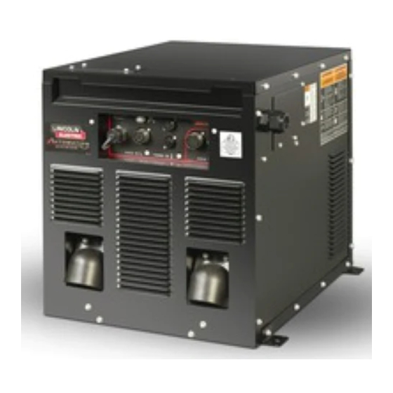
OPERATION PRODUCT DESCRIPTION The POWER WAVE i400 utilizes the latest genera- ® tion high speed digital controls, and communicates via ArcLink XT to the Fanuc controller. The inverter ® PRODUCT SUMMARY power section utilizes state of the art power electron- ics and is re-connectable for 3 phase input voltages General Physical Description from 208 to 575VAC. -
Page 31: Case Front Controls
OPERATION CASE FRONT FIGURE B.1 CASE FRONT CONTROL DESCRIPTION 1. Machine Status Indicator: A two color LED that NOTE: The POWER WAVE i400 status light will ® indicates system errors. The POWER WAVE i400 ® flash green, and sometimes red and green, for is equipped with two indicators. -
Page 32: Case Back Controls
OPERATION 2. THERMAL INDICATOR (THERMAL OVERLOAD): A Single Tach input +15V Tach supply yellow light that comes on when an over temperature sit- uation occurs. Output is disabled and the fan continues Tach common Open Reserved for future use to run, until the machine cools down. When cool, the GND-A Shielding drain light goes out and output is enabled. -
Page 33: Duty Cycle
OPERATION 5. CHASSIS POWER TERMINAL BLOCK (3TB): Power connec- INTERNAL CONTROLS tion for internal chassis. Provides power for the inverter and all FIGURE B.3 auxiliary supplies. 6. INPUT POWER TERMINAL BLOCK (1TB): Input power connec- tion from main service disconnect. 7. -
Page 34: Basic Welding Controls
Electric sales representative. Trim To make a weld, the Power Wave i400 needs to know In pulse synergic welding modes (GMAW-P), the Trim the desired welding parameters. The robot controller setting adjusts the arc length. Trim is adjustable from sends the parameters from the teach pendant (arc 0.50 to 1.50. - Page 35 OPERATION Non Synergic CV Pulse welding modes are synergic; using wire feed In non-synergic modes, the machine behaves like a speed as the main control parameter. As the wire conventional power source. The WFS and voltage feed speed is adjusted, the power source adjusts the are independent adjustments.
-
Page 36: Accessories
ACCESSORIES OPTIONAL EQUIPMENT FACTORY INSTALLED None Available. FIELD INSTALLED K940-Work Voltage Sense Lead Kit K2670-[ ] CE Filter Kit K2677-2 Integration Kit COMPATIBLE LINCOLN EQUIPMENT K2685-2 Auto Drive 4R90 Wire feeder (14-pin control cable). K1780-2 Power Feed 10 Robotic Wire Drive For additional Information see Optional Equipment in the Installation Section. -
Page 37: Maintenance
MAINTENANCE SAFETY PRECAUTIONS CHASSIS REMOVAL PROCEDURE WARNING WARNING ELECTRIC SHOCK can kill. ELECTRIC SHOCK can kill. • Do not touch electrically live parts or • Disconnect input power before electrode with skin or wet clothing. servicing. • Insulate yourself from work and •... - Page 38 MAINTENANCE 4. Remove the left case side by pulling out from the bottom. 5. Disconnect the chassis input power leads (1E, 2E & 3E) from terminal block “3TB” located in the cabinet reconnect area, and remove the chassis ground from the stud located in front the terminal block. 6.
-
Page 39: Troubleshooting
HOW TO USE TROUBLESHOOTING GUIDE WARNING Service and Repair should only be performed by Lincoln Electric Factory Trained Personnel. Unauthorized repairs performed on this equipment may result in danger to the technician and machine operator and will invalidate your factory warranty. For your safety and to avoid Electrical Shock, please observe all safety notes and precautions detailed throughout this manual. -
Page 40: Using The Status Led To Troubleshoot System Problems
TROUBLESHOOTING USING THE STATUS LED TO TROUBLESHOOT SYSTEM PROBLEMS The POWER WAVE i400 is equipped with two exter- ® nally mounted status lights, one for the power source, and one for the wire drive module contained in the power source. If a problem occurs it is important to note the condition of the status lights. -
Page 41: Error Codes For Power Wave
TROUBLESHOOTING Observe all Safety Guidelines detailed throughout this manual ERROR CODES FOR THE POWER WAVE ® The following is a partial list of possible error codes for the POWER WAVE i400. For a complete listing consult ® the Service Manual for this machine. POWER SOURCE–––WELD CONTROLLER LECO Indication... - Page 42 TROUBLESHOOTING Observe all Safety Guidelines detailed throughout this manual ERROR CODES FOR THE POWER WAVE ® The following is a partial list of possible error codes for the POWER WAVE i400. For a complete listing consult ® the Service Manual for this machine. WIRE DRIVE MODULE LECO Error Code #...
- Page 43 CAUTION If for any reason you do not understand the test procedures or are unable to perform the tests/repairs safely, con- tact your local authorized Lincoln Electric Field Service Facility for technical assistance. POWER WAVE i400...
- Page 44 Output Rectifier heat sinks, and Choke assembly. CAUTION If for any reason you do not understand the test procedures or are unable to perform the tests/repairs safely, con- tact your local authorized Lincoln Electric Field Service Facility for technical assistance. POWER WAVE i400 ®...
-
Page 45: Troubleshooting Guide
CAUTION If for any reason you do not understand the test procedures or are unable to perform the tests/repairs safely, con- tact your local authorized Lincoln Electric Field Service Facility for technical assistance. POWER WAVE i400... - Page 46 TROUBLESHOOTING Observe all Safety Guidelines detailed throughout this manual PROBLEMS POSSIBLE RECOMMENDED (SYMPTOMS) CAUSE COURSE OF ACTION WELD AND ARC QUALITY PROBLEMS Wire burns back to tip at the end of 1. Burnback Time. 1. Reduce burnback time and/or the weld. workpoint.
- Page 47 TROUBLESHOOTING Observe all Safety Guidelines detailed throughout this manual PROBLEMS POSSIBLE RECOMMENDED (SYMPTOMS) CAUSE COURSE OF ACTION WELD AND ARC QUALITY PROBLEMS Arc loss fault on robot. 2. Conduit leading to the wire feed- 2. Remove bends and twists in er has bends or twists, which conduit leading to the feeder.
- Page 48 E-10 E-10 TROUBLESHOOTING Observe all Safety Guidelines detailed throughout this manual PROBLEMS POSSIBLE RECOMMENDED (SYMPTOMS) CAUSE COURSE OF ACTION Device goes off line during welding. 1. Interference / Noise. 1. Verify that DeviceNet cables are not running next to (in close proximity with) current carrying conductors.
- Page 49 E-11 E-11 TROUBLESHOOTING Observe all Safety Guidelines detailed throughout this manual PROBLEMS POSSIBLE RECOMMENDED (SYMPTOMS) CAUSE COURSE OF ACTION Output will not come on. 6. Other modules faulted. 6. Verify no other modules are faulted (all system Status Lights should be steady green).
- Page 50 E-12 E-12 TROUBLESHOOTING Observe all Safety Guidelines detailed throughout this manual PROBLEMS POSSIBLE RECOMMENDED (SYMPTOMS) CAUSE COURSE OF ACTION Analog Inputs donʼt respond or donʼt 1. Analog Scans Between Updates. 1. The DeviceNet tab of the Diagnostics respond quickly. Utility displays the POWER WAVE ʼs ®...
- Page 51 E-13 E-13 TROUBLESHOOTING Observe all Safety Guidelines detailed throughout this manual PROBLEMS POSSIBLE RECOMMENDED (SYMPTOMS) CAUSE COURSE OF ACTION Bad Weld Ending. 1. Burnback Disabled. 1. From the DeviceNet tab of the Diagnostics Utility, select Monitor. The Monitor window will be displayed. Verify under the “State Enabled”...
- Page 52 E-14 E-14 TROUBLESHOOTING Observe all Safety Guidelines detailed throughout this manual PROBLEMS POSSIBLE RECOMMENDED (SYMPTOMS) CAUSE COURSE OF ACTION DeviceNet – PLC Controlled System 4. Verify all welding setpoint values 4. Limit Errors Bad Welding. are within limits. 5. Gas 5.
- Page 53 DIAGRAMS ENHANCED DIAGRAM POWER WAVE i400 ®...
- Page 54 DIMENSION PRINT POWER WAVE i400 ®...
- Page 55 Do not touch electrically live parts or Keep flammable materials away. Wear eye, ear and body protection. WARNING electrode with skin or wet clothing. Insulate yourself from work and ground. Spanish No toque las partes o los electrodos Mantenga el material combustible Protéjase los ojos, los oídos y el AVISO DE bajo carga con la piel o ropa moja-...
- Page 56 Keep your head out of fumes. Turn power off before servicing. Do not operate with panel open or WARNING Use ventilation or exhaust to guards off. remove fumes from breathing zone. Spanish Los humos fuera de la zona de res- Desconectar el cable de ali- No operar con panel abierto o AVISO DE...
- Page 57 Need Help? Lincoln Electric “Rapid Response” Service! Call 1.888.935.3877 to talk to a Service Representative Hours of Operation: 8:00 AM to 6:00 PM (ET) Mon. thru Fri. After hours? Use “Ask the Experts” at lincolnelectric.com A Lincoln Service Representative will contact you no later than the following business day.
Need help?
Do you have a question about the POWER WAVE I400 and is the answer not in the manual?
Questions and answers