Table of Contents
Advertisement
Quick Links
Advertisement
Table of Contents

Related Manuals for ADT 4-channel DVR


Summary of Contents for ADT 4-channel DVR
-
Page 3: Compliance Notice Of Fcc
4-Channel Digital Video Recorder WARNING RISK OF ELECTRIC SHOCK DO NOT OPEN WARNING: TO REDUCE THE RISK OF ELECTRIC SHOCK, DO NOT REMOVE COVER (OR BACK). NO USER-SERVICEABLE PARTS INSIDE. REFER SERVICING TO QUALIFIED SERVICE PERSONNEL. The lightning flash with arrowhead symbol, within an equilateral triangle, is intended to alert the user to the presence of uninsulated "dangerous voltage"... -
Page 4: Important Safeguards
User’s Manual Important Safeguards 1. Read Instructions 14. Damage requiring Service All the safety and operating instructions should be read before the Unplug this equipment from the wall outlet and refer servicing to qualified service personnel under the following conditions: appliance is operated. -
Page 5: Table Of Contents
4-Channel Digital Video Recorder Table of Contents Chapter 1 ─ Introduction ......................1 Features ..........................1 Technical Overview ........................ 1 Chapter 2 ─ Installation ......................3 Package Contents ........................3 Required Installation Tools ....................3 Video Input......................... 3 Video Loop Through ......................3 Video Out ........................... - Page 6 User’s Manual Pre-Event ......................... 23 Event Setup ......................... 24 Alarm-In ........................... 24 Motion Detection ......................25 Video Loss ........................27 System Event ........................28 Event Status ........................30 Chapter 4 ─ Operation ......................31 Turning on the Power ......................31 Live Monitoring ........................
- Page 7 4-Channel Digital Video Recorder List of Illustrations Figure 1 ─ Typical DVR installation......................2 Figure 2 ─ DVR rear panel......................... 3 Figure 3 ─ DVR front panel........................7 Figure 4 ─ Infrared Remote Control......................9 Figure 5 ─ Login screen..........................9 Figure 6 ─...
- Page 8 User’s Manual...
-
Page 9: Chapter 1 ─ Introduction
4-Channel Digital Video Recorder Chapter 1 ─ Introduction Features Your color digital video recorder (DVR) provides recording capabilities for four camera inputs. It provides exceptional picture quality in both live and playback modes, and offers the following features: 4 Composite Video Input Connectors ... -
Page 10: Figure 1 ─ Typical Dvr Installation
User’s Manual Figure 1 ─ Typical DVR installation. -
Page 11: Chapter 2 ─ Installation
4-Channel Digital Video Recorder Chapter 2 ─ Installation Package Contents The package contains the following: Digital Video Recorder Power Cord User’s Manual (This Document) RAS Software CD and User’s Manual USB Mouse Infrared Remote Control Required Installation Tools No special tools are required to install the DVR. -
Page 12: Video Out
User’s Manual Video Out Connect the main monitor to the Video Out connector. A VGA connector is provided so that you can use a standard, multi-sync computer monitor as your main monitor. Use the cable supplied with your monitor to connect it to the DVR. The VGA monitor is automatically detected when you connect it. -
Page 13: Network Port
4-Channel Digital Video Recorder Network Port The DVR can be networked using the 10/100Mb Ethernet connector. Connect a Cat5 cable with an RJ-45 jack to the DVR connector. The DVR can be networked with a computer for remote monitoring, searching, configuration and software upgrades. - Page 14 User’s Manual...
-
Page 15: Chapter 3 ─ Configuration
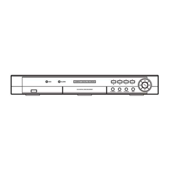
4-Channel Digital Video Recorder Chapter 3 ─ Configuration NOTE: Your DVR should be completely installed before proceeding. Refer to Chapter 2 ─ Installation. Front Panel Controls Figure 3 ─ DVR front panel. HDD LED Alarm LED Camera Buttons Play/Pause Button Arrow Buttons Menu Button PTZ/Zoom Button... -
Page 16: Play/Pause Button
User’s Manual Play/Pause Button In the live monitoring mode, pressing the button freezes the current screen and the screen displays icon. When in the playback mode, pressing the button pauses playing video. Pressing the button selects a highlighted item or completes an entry that you have made during system setup. Arrow Buttons These buttons are used to navigate through menus and GUI. -
Page 17: Id Button On Remote Control
4-Channel Digital Video Recorder ID Button on Remote Control If a DVR System ID is set to 0, the infrared remote control will control that DVR without any additional operations. (Refer to the Information setup screen in this chapter for further information on setting the System ID.) If the system ID is 1 to 4, you must to press the button on the remote control and then press the number button (1 to 4) in order to... -
Page 18: Setup Screen
User’s Manual NOTE: To log the user out of the system, press the button on the front panel or move the mouse pointer MENU to the top of the screen and then select (Logout) in the Live Monitoring menu. The Logout screen displays asking you to confirm whether or not you want to log out the current user. -
Page 19: Information
4-Channel Digital Video Recorder Information Highlight Information and press the button. The Information setup screen appears. In the Information screen, you can name the site location, assign a System ID number, select the language the screens are displayed in, display software version number, upgrade the software, show the System Log, change a password, display recorded time data, and clear all data. -
Page 20: Date/Time
User’s Manual NOTE: Even after changing the DVR settings by importing saved settings, the time-related settings (Date/Time, Time Zone and Daylight Saving Time) will NOT be changed. Highlight Show System Log… and press the button to display the System Log. The System Log screen lists system activities (up to 5,000 from the latest) that have occurred along with the time and date. -
Page 21: Storage
4-Channel Digital Video Recorder Highlight the Holiday tab, and the Holiday setup screen appears. You can set up holidays by highlighting + and pressing the button. The current date appears. Highlight the month and day and change them by using the Up and Down arrow buttons. -
Page 22: Shutdown
User’s Manual The Type column displays the type of storage device. The Disk Bad column displays the percentage of bad sectors. Not formatted indicates the device is not formatted. The Temperature column displays the temperature of the storage device. Good – The temperature is normal. ... -
Page 23: Figure 16 ─ Network Setup Screen
4-Channel Digital Video Recorder Highlight the first box beside Remote Watch – Transfer Speed. Press the Up and Down arrow buttons to set the Transfer Speed from 50Kbps to 100Mbps. Highlight the second box beside Remote Watch – Transfer Speed. You can select the unit of measure for the transfer speed between: bps and ips. - Page 24 User’s Manual Change the numbers by highlighting them and using the Up and Down arrow buttons to increase or decrease the number. The factory default Port settings are: Remote Admin: 8200 Remote Callback: 8201 Remote Watch: 8016 Remote Search: 10019 NOTE: You will need to get the appropriate Port Numbers for each RAS and WebGuard related program (Admin, Callback, Watch and Search) from your network administrator.
-
Page 25: Notification
4-Channel Digital Video Recorder Highlight Enable DVR Name Service and press the button to toggle between On and Off. NOTE: The DVRNS (DVR Name Service) allows the DVR to use Dynamic IP addresses for remote connection. When this feature is On, you can access your DVR remotely using the DVR name instead of its IP address. -
Page 26: Figure 20 ─ Notification Mail Setup Screen
User’s Manual Highlight Notification in the Network menu and press the button. The Notification setup screen displays. You will be able to change the Mail and Callback settings. Highlight Enable and press the button to toggle between On and Off. You will only be able to change the settings if Mail is enabled. -
Page 27: Devices Setup
4-Channel Digital Video Recorder Devices Setup Figure 22 ─ Devices menu. Camera Highlight Camera in the Devices menu and press the button. The Camera setup screen appears. You can turn the camera number On or Off, and you can change the Title of each camera using the virtual keyboard. Figure 23 ─... -
Page 28: Alarm-Out
User’s Manual Highlight the Setup… box and press the button. The Port Setup window appears. Configure the port’s setting based on the PTZ camera manufacturer’s instructions. Alarm-Out Highlight Alarm-Out in the Devices menu and press the button. The Alarm-Out screen appears. The alarm output can be given its title by highlighting the box under the Title heading and pressing the button. -
Page 29: Recording Setup
4-Channel Digital Video Recorder Highlighting the OSD Margin… box and pressing the button displays how OSD text will be displayed on the monitor. You can adjust the horizontal and vertical margins so that text and icons will not be hidden beyond the edges of the monitor. Highlight the Main Monitor tab, and the Main Monitor setup screen appears. -
Page 30: Record
User’s Manual Record Highlight Record in the Record menu and press the button. The Record setup screen appears. Highlighting Recycle and pressing the button toggles between On and Off. In the Recycle mode, the DVR records over the oldest video data once all available storage space has been used. -
Page 31: Pre-Event
4-Channel Digital Video Recorder You can program the DVR to record only during certain times based on time, day of the week, and holidays. The smallest time segment you can use is 15 minutes. Highlighting Schedule On and pressing the button toggles between On and Off. -
Page 32: Event Setup
User’s Manual When the DVR is in the Event Record mode it is possible to have it record images before the event occurs. The Pre-Event screen allows you to define how to handle pre-event recording. You can turn individual cameras On or Off for pre-event recording. -
Page 33: Motion Detection
4-Channel Digital Video Recorder You can set the actions the DVR will take whenever it senses an input on one of its alarm input connectors. Highlight the desired box under the Record heading, and press the button. A list of cameras appears. Select the cameras that you want the DVR to record whenever it detects an input on the associated alarm input. - Page 34 User’s Manual Highlighting the box under the Sensitivity heading and pressing the button allows you to adjust the DVR’s sensitivity to motion for Daytime and Nighttime independently. There are five settings with 1 being the least sensitive and 5 being the most sensitive. You can define the area of the image where you want to detect motion;...
-
Page 35: Video Loss
4-Channel Digital Video Recorder The DVR can be set to react to motion detection differently for each camera. Each camera can be associated with another camera, trigger an Alarm-Out connector, sound the DVR’s internal buzzer, notify a number of different devices, and/or move PTZ cameras to preset positions. -
Page 36: System Event
User’s Manual Highlight the Actions tab, and the Video Loss Actions setup screen appears. The DVR can be set to react to video loss differently for each camera. Each camera can be associated with another camera, trigger an Alarm-Out connector, sound the DVR’s internal buzzer, notify a number of different devices, and/or move PTZ cameras to preset positions. -
Page 37: Figure 41 ─ Storage Setup Screen
4-Channel Digital Video Recorder Highlight the Setup... box beside Check Recording and press the button. The Check Recording screen appears. Highlighting Schedule On and pressing the button toggles On and Off. When set to On, you can select the day, time range and interval that you want the DVR to run self-diagnostics on the recorder. -
Page 38: Event Status
User’s Manual Highlight the Notify box beside the desired event (System, Boot Up, Restart, Shutdown, Check Recording, Check Alarm-In, Disk Almost Full, Disk Full, Disk Bad, Disk Temperature, Disk S.M.A.R.T., Disk Config Change or Fan Error), and press the button. You can toggle the entire list On and Off by highlighting Notification and pressing button. -
Page 39: Chapter 4 ─ Operation
4-Channel Digital Video Recorder Chapter 4 ─ Operation NOTE: This chapter assumes your DVR has been installed and configured. If it has not, please refer to Chapters 2 and 3. The DVR’s controls are similar to a VCR. As with a VCR, the main functions are recording and playing back video. However, you have much greater control over recording and playing back video. -
Page 40: Zoom Mode
User’s Manual Sequence Selecting (Sequence) in the Live Monitoring menu causes the cameras to display sequentially. It is the same as pressing and holding the button on the front panel for three seconds or longer. Selecting again in the Live MENU Monitoring menu exits the Sequence mode. -
Page 41: Ptz Mode
4-Channel Digital Video Recorder PTZ Mode If a user who has PTZ Control authority logs into the system, the user can control PTZ cameras. The DVR will control cameras with Pan, Tilt and Zoom capabilities. Select PTZ from the Camera Menu in the Live Monitoring menu or press and hold the button on the front panel for three seconds or longer to display the PTZ camera menu and enter the PTZ mode. -
Page 42: Using A Mouse
User’s Manual Using a Mouse You can use a mouse instead of the front panel buttons to perform many of the DVR functions. In the Live Monitoring mode or Search mode, moving the mouse pointer to the left edge of the screen displays the following Mouse Display menu. Full Screen Previous Camera Next Camera... -
Page 43: Playing Recorded Video
4-Channel Digital Video Recorder Playing Recorded Video If a user who has Search authority logs into the system, the user can view recorded image. Once video has been recorded, you can view it by pressing the button. When playing video for the first time, the DVR will display the PLAYBACK most recent image. -
Page 44: Search Menu
User’s Manual NOTE: The Search menu also can be displayed by moving the mouse pointer to the top of the screen. Search Menu Search Selecting (Search) in the Search menu displays the following Search menu. See the following Event Log Search and Calendar Search sections for details. -
Page 45: Event Log Search
4-Channel Digital Video Recorder Alarm Reset Selecting (Alarm Reset) in the Search menu resets the DVR’s outputs including the internal buzzer during an alarm. It is the same as pressing any button on the front panel when the alarm is activated. Data Source (Data Source) in the Search menu allows you to select the data source to be searched. -
Page 46: Calendar Search
User’s Manual Highlight the box beside Video Loss and press the button. You can select the cameras for which you want any reports of lost video. Highlight the box beside Record Channels and press the button. You can select the cameras that you want to search for any reports of event recorded data. -
Page 47: Figure 51 ─ Clip-Copy Screen
4-Channel Digital Video Recorder You can search video from the first to last recorded images, or you can set the start and stop times and dates. Highlight the box beside From and press the (Play/Pause) button to set a specific Date and Time. Highlight the box beside To and press the button to set a specific Date and Time. - Page 48 User’s Manual...
-
Page 49: Appendix
4-Channel Digital Video Recorder Appendix Time Overlap If the DVR’s time and date have been reset to a time that is earlier than the existing recorded video, it is possible for the DVR to have more than one video stream in the same time range. In this case, you can search overlapping video streams individually by selecting a specific segment. -
Page 50: Web Monitoring Mode
User’s Manual Start Internet Explorer on your local PC. You can run the WebGuard program by entering the following information in the address field. “http://IP address:port number” (The DVR IP address and the WebGuard port number (default: 12088) set in the –... - Page 51 4-Channel Digital Video Recorder ① Click the to log out the WebGuard program. ② Click the to access to the web search mode. ③ Position the mouse pointer on the WebWatch logo to see the version of the WebGuard program. ④...
-
Page 52: Web Search Mode
User’s Manual Web Search Mode WebSearch is a remote web search program that allows you to search recorded video on the remote DVR. NOTE: The remote site connection in the Web Search mode will automatically be disconnected if there is no activity for 30 minutes. -
Page 53: Connector Pin Outs
4-Channel Digital Video Recorder ⑬ The timetable displays recorded data of the selected camera by time (in hour segments). ⑭ Selecting a camera on the screen and clicking the right mouse button displays the text menu screen. Change Camera Title: Changes the camera name. ... -
Page 54: System Log Notices
User’s Manual System Log Notices Boot Up Setup End Format Disk Shutdown Remote Setup Change Disk Full Restart Remote Setup Fail Auto Deletion Upgrade Setup Imported Search Begin Upgrade Fail Setup Import Failure Search End Time Change Setup Exported Clip-Copy Begin Time Zone Change Setup Export Failure Clip-Copy End... -
Page 55: Map Of Screens
4-Channel Digital Video Recorder Map of Screens Specifications VIDEO Signal Format NTSC or PAL (Auto Detect) Video Input Composite: 4 looping inputs, 1 Vp-p, auto-terminating, 75 Ohms Composite: 1 BNC, 1 Vp-p, 75 Ohms Monitor Outputs VGA: 1 (Auto Detect) Composite: 720x480 (NTSC), 720x576 (PAL) Video Resolution VGA: 720x480@60Hz (NTSC), 720x576@75Hz (PAL) - Page 56 User’s Manual INPUTS/OUTPUTS Alarm Input 4 TTL, programmable as NC or NO, 4.3V threshold 1 relay output, terminal blocks, programmable as NC or NO, 2A@125VAC, Alarm Output 1A@30VDC Alarm Reset Input 1 TTL, terminal block Internal Buzzer 80dB at 10cm Network Connectivity 10/100 Mbps Ethernet (RJ-45) CONNECTORS...
Need help?
Do you have a question about the 4-channel DVR and is the answer not in the manual?
Questions and answers