
Related Manuals for ergoline ergoselect 100


Summary of Contents for ergoline ergoselect 100
- Page 1 100 / 200 Bicycle Ergometer Operator's Manual 2010000134000 • Version 04/2011 • English...
- Page 2 No part of this manual may be reprinted, translated or reproduced without the manufacturer's written permission. This manual is not subject to any change order service. Please contact the manufacturer for the latest document revision. ergoline GmbH Lindenstraße 5 72475 Bitz Germany Tel.:...
-
Page 3: Table Of Contents
ontents Declaration of Conformity General Information Safety Information Intended Use Setup and Mains Connection Controls and Indicators Transport Setup Mounting the Control Terminal (P or K) Connecting the Power Cord Connecting the Blood Pressure Cuff Transport Preparing the Patient Adjusting the Saddle and the Handlebar Preparing the Patient for Blood Pressure Measurements Checking the Cuff Tubing Operation... - Page 4 - 4 -...
-
Page 5: Declaration Of Conformity
eClaration of onformity - 5 -... - Page 6 - 6 -...
-
Page 7: General Information
• This manual reflects the equipment specifications and applicable safety standards valid at the time of ergoline GmbH printing. All rights are reserved for devices, circuits, Lindenstrasse 5 techniques, software programs, and names appearing 72475 Bitz in this manual. Germany • On request ERGOLINE will provide a Field Service Phone: +49-(0)-7431 - 9894 -0 Manual. Fax: +49-(0)-7431 - 9894 -128 e-mail: info@ergoline com http: www ergoline com / www ergoline eu - 7 -... -
Page 8: Safety Information
Explosion hazards may result from the use of flammable anes- leakage currents do not present a hazard. thetics, skin cleansing agents or disinfectants. In case of questions, please contact your ERGOLINE dealer or the ergoline GmbH Service Department. For use, the ergometer must always be connected to electric Warning installations that fulfill the local requirements. -
Page 9: Intended Use
In certain cases, a valid measurement will not be possible. requirements of the applicable standards if applied as intended. Electromagnetic fields are also capable of impairing the mea- suring accuracy. If you have questions in this matter, please contact ERGOLINE or a representative. Note • The blood pressure module and the approved accessories PPliCaBle eGulations anD are defibrillation-proof and may remain attached to the patient during defibrillation. - Page 10 Additional equipment connected to medical electrical equipment must comply with the respective IEC or ISO standards (e.g. IEC 60950 for data processing equipment). Furthermore all configurations shall comply with the re‑ quirements for medical electrical systems (see IEC 60601‑ 1‑1 or clause 16 of the 3Ed. of IEC 60601‑1, respectively). Anybody connecting additional equipment to medical electrical equipment config ures a medical system and is therefore responsi ble that the system complies with the requirements for medical electrical systems. Attention is drawn to the fact that local laws take priority over the above mentioned requirements. If in doubt, consult your local representative or the technical service department.“ (Standard / directive references: · IEC 60601‑1+Al +A2:1995: 6.8.2.c, 19.2.b, 19.2.c, · IEC 60601‑1:2005: 7.9.2.5, 8.1, 16.2.d, · MDD 93142lEEC: Annex I clause 13.6.c - 10 -...
-
Page 11: Setup And Mains Connection
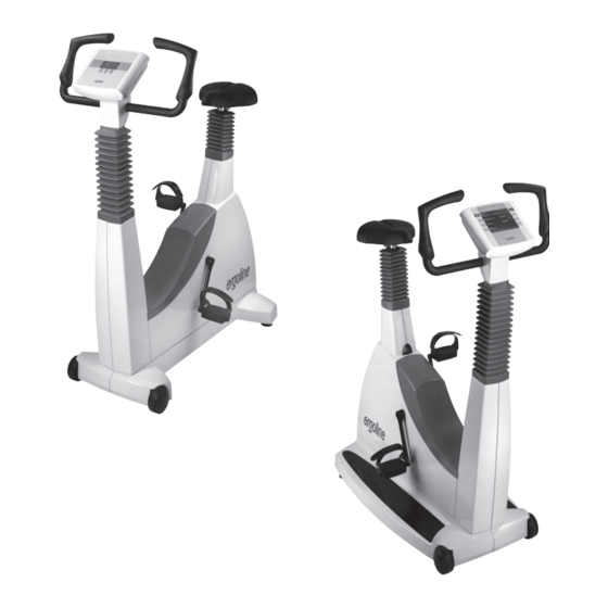
etuP anD ains onneCtion ontrols anD nDiCators 1 Control terminal (model P or model K) 2 Blood pressure cuff connection (option) 3 Adjustment of the handlebar angle 4 Blood pressure cuff 5 Adjustment of the handlebar height (ergoselect 200 only) 6 Castors 7 Speed display (RPM) for patient 8 Adjustment of the saddle height (ergoselect 100 only) 9 Digital saddle height indication (ergoselect 200 only) 100 - ergoselect controls connections and indicators 10 Power switch (green button) 11 Sockets for power cord and connection cables ( underside of ergometer) 12 Levelling devices to adjust the ergometer to uneven floors 200 -... -
Page 12: Transport
ransPort For short distances, the ergoselect can be lifted at the Caution saddle and rolled away on its castors. • Equipment Damage • To cover greater distances, however, we recommend the following method: Avoid strong vibrations of the ergoselect during transport. • Disconnect the power cord from the wall outlet. • Rotate the handlebar towards the front. Tighten the clamping lever. • Stand in front of the ergoselect, grasp the handlebar and tilt the ergoselect towards you until it is standing on the castors only and is balanced. • It is now possible to transport the ergoselect. • When you have reached the new location, lower the ergoselect very carefully to avoid damage. ransporting the ergoselect etuP Place the ergoselect on a level floor. The ergoselect must be set up in a secure and stable posi‑ tion ‑ the two levelling feet at the back make for easy adjustment to uneven floor surfaces. Extend the foot concerned until the ergoselect no longer wobbles. -
Page 13: Mounting The Control Terminal (P Or K)
ountinG the ontrol erminal The control terminal can be installed with the display either facing the patient or the operator. It is recommended to install the terminal with the display and control keys towards the operator and the speed display towards the patient. ifferent orientations of the control terminal onneCtinG the ower Set the handlebar to the front upper position and secure. Tilt the ergoselect carefully towards you until it rests on the handlebar. ssembly position of the ergoselect ergometer Caution • Equipment Damage • Before connecting the ergometer to the power line, check that the line voltage corresponds to the ratings on the type plate. - Page 14 The connection panel is located on the underside of the ergometer. • Plug the power cord into socket (a) and use the sup‑ plied lock (b) to secure it against disconnection. • Using the supplied strain relief, attach the cable to the metal frame. onnection panel Power input Lock ower cord with installed strain relief Hint • disconnection • Removing the power cord results in complete disconnection from mains (all poles). Danger • Patient Hazard • To insure a safe connection to the protective ground system, power cords of type „hospital only“...
- Page 15 PORT 1 Digital connection RS232 (remote control by PC or ECG recorder, Hint • connecting cables • Only use connecting cables released by ergoline. To use the integrated USB connector, a special driver is required - contact ergoline. - 15 -...
-
Page 16: Connecting The Blood Pressure Cuff
onneCtinG the looD ressure • Connect the microphone at (1). • Slip the cuff tubing onto the fitting (2) and engage. To disconnect, push back the connector's knurled sleeve. Artifacts that may be caused by patient movements during the exercise test, must be avoided if possible, while the lood pressure cuff connections blood pressure is being taken. Microphone connection Therefore, do not forget to attach the cuff tubing to the Cuff tubing handlebar with the supplied Velcro tape: • Open the large Velcro tape and wrap around handlebar. • Secure the cuff tubing with the small Velcro tape, but do not exert pressure on the tubing. elcro tape to secure the cuff tubing ransPort • Disconnect the power cord and the connection cables. • Stand in front of the ergometer, grasp the handlebar and tilt the ergometer towards you until it is standing on the castors only and balanced. -
Page 17: Preparing The Patient
Adjustment of the handlebar angle Adjustment of the handlebar height (ergoselect 200 only) Adjustment of the saddle height (ergoselect 100 only) Saddle height display (ergoselect 200 only) Note • Tighten the clamping levers only as far as necessary, NOT with maximum force. -
Page 18: Preparing The Patient For Blood Pressure Measurements
reParinG the atient for looD ressure easurements Always choose the cuff size suitable for the patient's arm. The maximum arm circumference is indicated on the cuff. orrect cuff size rong cuff size iCroPhone osition Before applying the cuff, check the position of the micro‑ phone inside the red pocket (on the inside of the cuff): When the microphone is inside the pocket, its metal side must face the arm. orrect microphone position PPlyinG the The center of the microphone must be located exactly on the brachial artery. Locate the artery by palpation, if required. The red tab identifies the position of the micro‑ phone. The accurate placement of the microphone is the primary condition for reliable pressure measurement during exer‑ cise tests. The cuff must be applied directly on the skin, it may not be applied on top of clothing, paper, etc. Apply the cuff a pprox. 2 cm above the bend of the elbow. The cuff should be tight, but it should not constrict blood vessels. -
Page 19: Checking The Cuff Tubing
When you close the Velcro strap, check that the metal clasp (a) is inside the marked index range (b), and not outside. The cuff tab must be located below the metal clasp (see illustration at right). orrect cuff position heCKinG the uBinG Check that the cuff tubing does not knock against the patient's knee, when the patient is pedalling and the hand is on the handlebar. Secure the cuff tubing with the Velcro tape attached to the handlebar. Instruct your patient to move as little as possible during a blood pressure measurement and, in particular, to avoid excessive contractions of the muscles in the upper arm. istance between Knee and tubing Caution • Patient Hazard • Apply the cuff directly on the skin. Make sure that rolled up sleeves do not impede blood circulation in the upper arm. - Page 20 - 20 -...
-
Page 21: Operation
Peration The ergometers of the ergoselect series are available with two versions of the control terminal whose functionalities differ. The following sections describe the control and configura‑ tion of the ergometer. Control terminal P Control terminal K ontrol terminal ergoline ergoline urninG the ystem You turn the ergometer on by pressing the power switch ‑ GmbH GmbH the green indicator in the switch lights up. The ergometer runs a self‑test. Subsequently, the main menu displays. Selftest running Note test screen • Instruct the patient not to pedal while the ergometer is being turned on and during the self-test. -
Page 22: Operating Modes With Control Terminal P
PeratinG oDes with ontrol erminal An ergoselect ergometer with a control terminal P sup‑ ports the following operating modes: PC MODE An external device (e.g. stand‑alone electrocardio‑ graph, PC‑based ECG system) controls the ergometer ‑ no intervention at all is required at the ergometer. ERGOMETRY The ergometer runs an automatic exercise test ‑ some of the corresponding test protocols are user‑configu‑ rable and stored in the system (see chapter "Settings"). MANUAL The ergometer is controlled manually, i.e., the user performs all load changes via the keypad. SETTINGS Used to configure the ergometer. PeeD reaDout At the top of the control terminal, there is a speed readout for the patient as well as three LEDs that inform the p atient of the speed: too slow, too fast or correct. The ranges for the respective speed ratings depend on the selected load (see "Technical Specifications"). peed readout speed low (patient should pedal faster) correct speed speed high (= patient should pedal slower) Note •... -
Page 23: Pc Mode
PC m Use the softkeys on the right and left (↑ ↓) to position the PC Mode bar cursor on PC MODE and confirm the selection with Ergometry SELECT. Manual Settings ↑ ↓ Select ain menu The display changes ‑ the ergometer is waiting for com‑ mands from the external ECG unit. With the arrrow keys, the saddle height can be electrically adjusted on the ergoselect 200 (on the ergoselect 400, these keys adjust the height of the drive unit). Saddle nitial screen As soon as the ergometer receives commands from the controlling ECG unit or PC, the exercise test will start and the corresponding values will be displayed. The exercise test can only be terminated with the corre‑ sponding command from the controlling ECG unit. PC Mode isplay during exercise test current load in watts most recent BP value (systolic/diastolic values) or cuff pressure during inflation duration of exercise test (min) heart rate at the time of the BP measurement (BPM) -
Page 24: Ergometry
rGometry Use the softkeys on the right and left (↑ ↓) to position the PC Mode bar cursor on ERGOMETRY and confirm the selection with Ergometry SELECT. Manual Settings Select ain menu Protocols The stored test protocols available for selection will be displayed. There are five fixed protocols (protocols 1 to 5, 1. WHO see Appendix) , whereas protocols 6 to 15 are user‑pro‑ 2. BAL grammable. 3. Hollmann The protocol menu provides an overview of the test 4. STD. France phases: 50 W / 2 min / 25 W 5. Standard e.g.: means: initial (basic) load 50 watts Select stage time 2 minutes load increment 25 watts electing an exercise test protocol Use the softkeys on the right and left (↑ ↓) to position the bar cursor on one of the protocols and confirm the selec‑... - Page 25 Note • The saddle height (ergoselect 200) can be changed during an exercise test. • To reactivate the saddle height adjustment function, press and the arrow keys will again be displayed. • Additional blood pressure measurements can be initiated with erminatinG an xerCise The exercise phase can be terminated manually at any time...
-
Page 26: Manual
anual Use the softkeys on the right and left (↑ ↓) to position the PC Mode bar cursor on MANUAL and confirm the selection with Ergometry SELECT. Manual Settings In this operating mode the user controls the entire exercise test by selecting the loads, stage times and by initiating blood pressure measurements. Select ain menu The exercise test is started with the "Start" key, afterwards the load can be set and changed with the +5 W and ‑5 W keys (in increments of +/‑1 W up to +/‑25 W, as config‑ ured). Blood pressure measurements an be initiated with Start + 5 W + 5 W - 5 W - 5 W nitial screen of a manual exercise test erminatinG an xerCise The exercise test can be terminated manually at any time with the END key located in the middle. The load will immediately drop to 0 watt. There is no recovery phase in the manual mode. + 5 W - 5 W creen display during the test - 26 -... -
Page 27: Settings With Control Terminal P
ettinGs with ontrol erminal Some of the device settings are configurable to meet spe‑ PC Mode cific requirements. The settings will be saved and remain Ergometry stored even when the ergometer is switched off. Manual Use the softkeys on the right and left (↑ ↓) to position the Settings bar cursor on SETTINGS and confirm the selection with SELECT. The configuration menu displays. Select When all changes have been made, you can exit the con‑ ain menu figuration menu with the key. Settings Default Mode Use the softkeys on the right and left (↑ ↓) to position the Protocols bar cursor on the parameter to change and confirm the Contrast selection with SELECT. Load Change Language Select onfiguration menu Default Mode efault Menu In this menu you choose the default mode activated when PC Mode the ergometer is turned on. When first turned on, the Ergometry ergometer will display this menu. - Page 28 Protocol Use the right and left softkeys ↑ ↓ to select the parameter to edit. Basic Load 25 W Stage Time 2 min Load Stage 25 W Select electing the parameter to edit Protocol When confirmed with SELECT, the corresponding value ap‑ pears in reverse video and can be changed with the arrow keys ↑ ↓. Basic Load 25 W Stage Time 2 min Load Stage 25 W Pressing SELECT will save the new value. Select All other parameters are edited in the same way. You exit the configuration with diting the parameter value Contrast ontrast The display contrast is adjustable in the range from 50 % 0 to 100%. Select djusting the display contrast Load Change hanGe +/-...
- Page 29 Language anGuaGe Deutsch The texts can be displayed in different English languages. Francais Espanol Italiano Auswahl anguage menu Beep The audio signal emitted during blood pressure measure‑ ments can be turned on and off. Off Select eep during measurements oftware ersion Select this option to view the installed software version. Date To begin with, you select DATE or TIME and confirm the 22. 08. 2007 selection. Then the value displayed in reverse video can be edited with the ↑ ↓ keys and saved with SELECT. Time The time is adjusted in the same way. 17 : 33 : 05 Select You exit the configuration with etting the date Date 22. 08. 2007 Time 17 : 33 : 05 Select etting the day - 29 -...
- Page 30 eKG t EKG Type The selected EKG Type determines the communication method with the ECG recorder, PC‑based ECG system, etc. To prevent an accidental change of this setting, the menu is protected with a password. Using the arrow keys, enter 003 and confirm the entry with SELECT. Select eKg t ntering the ype password All ergoselect ergometers support the following communi‑ cation modes: • Analog with pulse Remote start mode; prior the each load change, the ergometer generates a control pulse and sends the corresponding data via the interface. • Analog / Digital An analog voltage controls the load ‑ blood pressure measurements can be initiated with digital commands. • Digital (default) The communication with the ergo m eter is entirely controlled with digital commands. EKG Type • Analog IN‑OUT Analog with pulse The entire communication (load control and BP mea‑ Analog / Digital surements) is controlled with analog signals. Digital No digital data will be sent.
- Page 31 Here you determine the RPM limits. When these limits are exceeded, the LEDs for high or low speed (RPM) will Min ↑ 0 ... 70 illuminate. Select the value to change (Min. or Max.) and confirm with Max. ↓ 50 ... 130 SELECT. Using the arrow keys, change the value and save the new Select value with SELECT. etting the limit values Note • The limits selected in this menu only apply to the load range between 6 and 150 watts. At higher loads the RPM limits automatically adapt to the respective loads: Load (watts) Green RPM range (1/min)
-
Page 32: Control Terminal K
You turn the ergometer on by pressing the power switch ‑ the green indicator in the switch lights up. The ergometer runs a self‑test. Subsequently, the main GmbH GmbH menu displays. Selftest running test screen Note • Instruct the patient not to pedal while the ergometer is being turned on and during the self-test. • Apply the blood pressure cuff to the patient AFTER the ergometer has been turned on and the self-test been completed. -
Page 33: Operating Modes With Control Terminal K
PeratinG oDes with ontrol erminal An ergoselect ergometer with a control terminal K sup‑ ports the following operating modes: training sessions. PC MODE TEST An external device (e.g. stand‑alone electrocardio‑ Integrated test protocols (steep ramping test, PWC graph, PC‑based ECG system) controls the ergometer ‑ tests) allow an assessment of the physical fitness. no intervention at all is required at the ergometer. ERGOMETRY MANUAL The ergometer runs an automatic exercise test ‑ some The ergometer is controlled manually, i.e., the user of the corresponding test protocols are user‑configu‑ performs all load changes via the keypad. rable and stored in the system (see chapter "Settings"). TRAINING SETTINGS Ten different training protocols with warm‑up, exer‑ Used to configure the ergometer. cise and recovery phases can be custom‑configured (see chapter "Settings"). A POLAR receiver is integrated in the ergometer and provides the relevant data for heart‑rate controlled PeeD reaDout At the top of the control terminal, there is a speed readout for the patient as well as three LEDs that inform the p atient of the speed: too slow, too fast or correct. The ranges for the respective speed ratings depend on the selected load (see "Technical Specifications"). peed readout speed low (patient should pedal faster) correct speed speed high (= patient should pedal slower) -
Page 34: Pc Mode
PC m When the PC Mode key has been pressed, the screen appears as shown at right. The ergometer is waiting for commands from the external ECG unit. Saddle ↑ Saddle ↓ With the arrrow keys, the saddle height can be electrically adjusted on the ergoselect 200 (on the ergoselect 400, these key adjust the height of the drive unit). PC Mode: Waiting for start nitial screen in mode As soon as the ergometer receives commands from the controlling ECG unit or PC, the exercise test will start and the corresponding values will be displayed. The exercise test can only be terminated with the corre‑ sponding command from the controlling ECG unit. Note Exercise test running • All functions are locked while the ergometer is operating isplay during exercise test in PC mode, except for the saddle height adjustment and most recent BP value (systolic/diastolic pressures) or cuff the blood pressure key . -
Page 35: Ergometry
rGometry The ergometer is controlled by an internally stored proto‑ col. Ergometry WHO Pressing the "Ergometry" key will display the test protocol ↑ Saddle used last. Press the "Start" key to re‑start the protocol, or press the ↓ Saddle "Select" key to display the protocol parameters or to switch to another test protocol. Start Select There are five fixed protocols (protocols 1 ‑ 5, see Appendix), whereas protocols 6 ‑ 15 are user‑program‑ mable. Make settings nitial screen of an exercise test With the arrow keys you can display the test protocol. With "Select" you confirm the selection. Protocol WHO The selected exercise test is started with the "Start" key, a ↑ blood pressure measurement at rest may precede the test Basic Load 25 Watt (see "Settings"). Stage Time 2 min ↓... - Page 36 Djustments urinG the xerCise Press the key to display the configuration menu. This is what you can do during the test • increase or decrease the current load in increments (adjustable between 1 watt and 25 watts) Load + Recovery phase • hold the current load Load - • end the exercise phase and advance to the recovery phase Load const. Previous • terminate the test. Make settings onfiguration menu Pressing again displays another menu where you can change the saddle height and the display mode (see "PC Mode"). Saddle ↑ Saddle ↓ Previous Display Make settings onfiguration menu erminatinG the Once the full protocol has been completed, the test will be terminated.
-
Page 37: Manual
anual In this operating mode the user controls the entire exercise test by selecting the loads, stage times and by initiating blood pressure measurements. Load + Saddle ↑ The exercise test is started with the "Start" key, afterwards the load can be set and changed with the [Load +] and Load - Saddle ↓ [Load +] keys (in increments of 1 W up to 25 W, as config‑ ured). Start Blood pressure measurements can be initiated with Ergometry: Waiting for start creen display in manual mode erminatinG an xerCise The exercise test can be terminated manually at any time with the END key located in the middle. The load will immediately drop to 0 watt. There is no recovery phase in the manual mode. - 37 -... -
Page 38: Training
raininG Cardiologic training sessions can be performed with er‑ goselect ergometers equipped with control terminal K. Training No.1 Pulse For a detailed description of the protocols, please refer to ↑ Saddle the Appendix. Pressing the "Training" key will display the training proto‑ ↓ Saddle col used last. Press the "Start" key to re‑start the protocol, or press the Start Select "Select" key to display the protocol parameters or to switch to another training protocol. Make settings All training protocols 1 ‑ 10 are user‑configurable. (see "Settings for Control Terminals K"). nitial screen of the training session Use the arrow keys to display the protocol to use and the corresponding parameters. Confirm the selection with the "Select" key. Training No. 1 Pulse ↑ Basic Load 25 Watt You initiate the training session with the "Start" key. Warmup 2 min Training time 20 min The display changes to the training session screen, where ↓... -
Page 39: Training With Chip Card
• end the training session and advance to the recovery Recovery phase phase, • directly terminate the training session, End • change the display mode (see "PC Mode"). Previous Display Training running onfiguration menu raininG with As an alternative to the training protocols saved in the ergometer, it is possible to load training protocols from the chip card. The training protocols are saved to the chip card by means of a PC program ("ergoline opticare professional" or "ergo‑ line opticare basic"). Upon completion of the training session, the entire proce‑ dure (incl. load and heart rate waveforms) is saved to the chip card and can be reviewed and analyzed at the PC. tartinG the raininG ession Select the "Training" mode and insert the chip card into Training Chipcard the card reader (on the side of the control terminal). The ergometer switches to the chip card mode and reads the data stored on the card. Reading card! eading the chip card data... - Page 40 The name and the weight stored on the card are displayed. Training Chipcard Sumner You can use the arrow keys to enter the current weight. David Weight + 93 kg Weight - Press the "Next" key and the initial screen will display. You can initiate the displayed training protocol or select Next another protocol from the chip card. Make settings ntering the weight The chip card training session proceeds in the same way as the exercise tests stored in the ergometer. erminatinG the raininG ession After termination of the training session (automatic ter‑ Training Chipcard mination when the programmed recovery phase has been completed, or manual termination) the test subject can Stress state how the test was perceived (BORG scale). ↑ very very heavy very heavy heavy ↓ a little stronger easy very easy very very easy borg...
-
Page 41: Settings For Control Terminals K
ettinGs for ontrol erminals Some of the device settings are configurable to meet spe‑ cific requirements. The settings will be saved and remain stored even when the ergometer is switched off. Select SETTINGS to display the configuration menu. Settings Default Mode When all changes have been made, you can exit the con‑ Protocols figuration menu with the key. ↑ Contrast Load Change Language ↓ Beep Use the softkeys (↑ ↓) to position the bar cursor on the pa‑ Software Version rameter to change and confirm the selection with SELECT. Date/Time Select Training EKG Type Choose function onfiguration menu efault In this menu you choose the default mode activated when the ergometer is turned on. When first turned on, the ergometer will display this menu. Use the softkeys (↑ ↓) to position the bar cursor on your preferred default mode and save the selection with SELECT. Protocols rotoCols 1. - Page 42 Protocol Use the softkeys ↑ ↓ to select the parameter to edit. Basic Load 25 Watt ↑ Stage Time 2 min Load Stage 25 Watt NIBP Lead Time 60 sec ↓ Recovery Load 25 Watt Select Recovery Time 2 min Choose function electing the parameter to edit When confirmed with SELECT, the corresponding value ap‑ Protocol pears in reverse video and can be changed with the arrow keys ↑ ↓. Basic Load 25 Watt ↑ Stage Time 2 min Load Stage 25 Watt Pressing SELECT will save the new value.
- Page 43 hanGe Load Change Here you determine the increments for each load change. +/- 1 Watt Depending on your choice, each key press will change the ↑ +/- 5 Watt load by +/‑ 1, 5, 10 und 20 watts. +/- 10 Watt +/- 25 Watt ↓ Select electing the increment for manual load changes Language anGuaGe The texts can be displayed in different languages. Deutscht ↑ English Francais IBP-Espanol ↓ Italiano Select Choose function anguage menu The audio signal emitted during blood pressure measure‑ ments can be turned on and off. oftware ersion Select this option to view the ergometer's installed soft‑...
- Page 44 Date/Time To begin with, you select DATE or TIME and confirm the Date selection. ↑ 22. 08. 2007 Then the value displayed in reverse video can be edited Time with the ↑ ↓ keys and saved with SELECT. 17 : 33: 51 ↓ The time is set in the same way. Select You exit the configuration with Choose function etting the date Date/Time Date ↑ 22. 08. 2007 Time 17 : 33: 51 ↓ Select Choose function hanging the date Training raininG 1. Pulse Ten training protocols consisting of warmup, training and 2. Constant recovery phase are user‑configurable. Depending on the ↑ 3. Interval selected training mode (pulse, constant, interval), there will 4.
- Page 45 Training For all training modes (pulse, constant load and interval), the warmup phase, the duration of the training session Select Pulse and the recovery phase are defined first. Basic Load Watt Depending on the selected training mode, you can edit the ↑ Warmup 2 corresponding parameters afterwards: Training time • Pulse-controlled training: Recovery Load Watt ↓ Training pulse: 40 ‑ 250 1/min Recovery Time 3 Maximum load: 1 ‑ 999 Watt Load increment 8 W/min Training pulse 100 1/min • Constant load: Select Maximum load 50 Watt Training load: 1 ‑ 999...
- Page 46 eKG t EKG Type The selected EKG Type determines the communication method with the ECG recorder, PC‑based ECG system, etc. ↑ To prevent an accidental change of this setting, the menu is protected with a password. ↓ Using the arrow keys, enter 003 and confirm the entry with SELECT. Select Choose function eKg t ntering the ype password All ergoselect ergometers support the following communi‑ cation modes: • Analog with pulse Remote start mode; prior the each load change, the ergometer generates a control pulse and sends the corresponding data via the interface. • Analog / Digital An analog voltage controls the load ‑ blood pressure measurements can be initiated with digital commands. • Digital (default) EKG Type The communication with the ergometer is entirely controlled with digital commands. Analog with pulse ↑ Analog / Digital • Analog IN‑OUT The entire communication (load control and BP mea‑...
- Page 47 Here you determine the RPM limits. When these limits are exceeded, the LEDs for high or low speed (RPM) will Min ↑ 0 ... 70 ↑ illuminate. Max. ↓ 50 ... 130 Select the value to change (Min. or Max.) and confirm with ↓ SELECT. Using the arrow keys, change the corresponding value and Select save the new value with SELECT. Choose function etting the limit values Note • The limits selected in this menu only apply to the load range between 6 and 150 watts. At higher loads the RPM limits automatically adapt to the respective loads: Load (watts) Green RPM range (1/min)
-
Page 48: Cleaning, Maintenance, Disposal
leaninG aintenanCe isPosal Warning eneral leaninG • Shock Hazard • Wipe the device surface down with a cloth moistened with soap water or a disinfectant. • Disconnect the device from the power line before clean- The cloth should not be dripping wet; do not allow liquids ing. to enter the device. • Equipment Damage • Recommendeddisinfectants are, for example: ‑ Fugaten spray ‑ Lysoform or • Do not allow liquids to enter the equipment. ‑ Promanum N Devices into which liquids have entered must be immedi- ately cleaned and checked by a service technician, before... - Page 49 leaninG the looD ressure emovinG the iCroPhone Pull the end of the cuff through the metal clasp and fold out the cuff. Pull on the short Velcro tab to open the microphone pocket and carefully remove the microphone. emoving the icrophone Warning leaninG isinfeCtion • Equipment Damage • Clean the cuff and tubing with a moist cloth. You can use a dishwashing liquid or mild soap water. • Cuff, microphone and tubing may not under any circum- stances: Clean the microphone with a cloth moistened with alcohol - be immersed in liquids or soap water.
- Page 50 Before eaCh use Before each use, visually inspect the device for signs of damage. If you detect damages or impaired functions which may result in a hazard to the patient or the operator, the device must be repaired before it can be used again. eChniCal afety nsPeCtions anD eChniCal nsPeCtions of the easurinG ystem The technical safety inspections and the inspections of the measuring system must be completed every two years according to the rules of the art by a Service Engineer authorized by ergoline. Similarly, the automatic sphygmomanometer in the control terminal must be checked and calibrated by an authorized specialist every two years to fulfill legal requirements. The date of the next inspection is indicated on the inspection sticker attached next to the type plate on the e rgometer. isPosal The product described in this operator manual must not be disposed as unsorted municipal waste and must be col‑ lected separately. Please contact an authorized representative of the manu‑ facturer for information concerning the decommissioning of your equipment. - 50 -...
-
Page 51: Technical Specifications
• 5 fixed incremental exercise test protocols (e.g. WHO) • 10 user‑programmable protocols • manual load control • 4 fixed test protocols (e.g. PWC) • 10 user‑programmable training protocols Permitted Patient Weight 160 kg Saddle Height Adjustment continuous, for patients between 120 cm and 210 cm ergoselect 100: manual adjustment of saddle height ergoselect 200: electrical adjustment of saddle height with digital readout Handlebar Adjustment for patient heights between 120 cm and 210 cm continuous handlebar adjustment over 360° ergoselect 100: rigid steering column ergoselect 200: height‑adjustable steering column Crank Length 170 mm (cranks with adjustable length are optional... - Page 52 Displays LCD: 68 x 34 mm, 128 x 64 pixels (Control Terminal P) 115 x 88 mm, 320 x 240 pixels (Control Terminal K) additional LED display for speed (RPM) Interfaces PORT 1 (DSUB‑9‑pole): digital remote control RS232 by PC or ECG recorder, remote start of ECG recorder (optional) USB: digital remote control by PC (driver required) Dimensions, Weight length: 900 mm width: 460 mm (width of handlebar: approx. 575 mm) height: 900 mm to 1350 mm weight: approx. 64 kg (ergoselect 100) approx. 68 kg (ergoselect 200) Safety Standards DIN EN 60601‑1, DIN EN 60601‑1‑2, DIN VDE 0750‑238 Protection Class / Degree of Protection II / B (to DIN EN 60601‑1) MDD Classification class IIa to 93/42 EEC RF Emission class B to DIN EN 55011 / 5.0 DIN EN 60601‑1‑2 Environment operation:...
- Page 53 Max. Cuff Pressure 300 mmHg Cuff Deflation Method pulse‑dependent deflation rate approx. 3 mmHg/beat or approx. 3 mmHg/s Calibration calibration with external pressure meter Artifact Rejection automatic artifact rejection and comparison of the rest‑ ing BP readings from both methods for plausibility xerCise rotoCols Protocol initial load time in stage load recovery load recovery time [min] increment [min] 1. WHO 2. BAL 3. Hollmann 4. STD France 5. Standard 6. ‑ 15. (user‑programmable) Adjustment Range 20 ‑ 100 1 ‑ 30 1 ‑ 400 20 ‑ 100 (*)
- Page 54 amily of CharaCteristiCs of the BraKinG torque Control ranGe black: speed‑independent range to DIN VDE 0750‑0238 black + grey: speed‑independent range of the ergoselect ergometer ieC 60601‑1 amily of CharaCteristiCs of loaD Duration Due to Under permanent load conditions the shown load and pause times (white) have to be observed. - 54 -...
- Page 55 Use of portable telephones or other radio frequency (RF) Changes or modifications to this system not expressly emitting equipment near the system may cause unexpect- approved by ergoline could cause EMC issues with this or ed or adverse operation. other equipment...
- Page 56 ’ – e uiDanCe anD anufaCturer eClaration leCtromaGnetiC mmunity The ergoselect ergometer is intended for use in the electromagnetic environment specified below It is the responsibil- ity of the customer or user to ensure that the ergoselect ergometer is used in such an environment ImmunityTest IEC 60601 Test Level Compliance Level...
- Page 57 ’ – e uiDanCe anD anufaCturer eClaration leCtromaGnetiC mmunity The ergoselect ergometer is intended for use in the electromagnetic environment specified below It is the responsibil- ity of the customer or user to ensure that the ergoselect ergometer is used in such an environment ImmunityTest IEC 60601 Test Level Compliance Level...
- Page 58 eCommenDeD seParation DistanCes Between PortaBle anD moBile CommuniCations equiPment anD the erGoseleCt erGometer The ergoselect ergometer is intended for use in the electromagnetic environment in which radiated RF disturbances are controlled The customer or the user of the ergoselect ergometer can help prevent electromagnetic interference by maintaining a minimum distance between portable and mobile RF communications equipment (transmitters) and the ergoselect ergometer as recommended below, according to the maximum output power of the communications equipment Rated Maximum...
- Page 60 GmbH Lindenstraße 5 72475 Bitz Germany Tel.: +49-(0) 7431 98 94 - 0 Fax: +49-(0) 7431 98 94 - 128 e-mail: info@ergoline.com http: www.ergoline.com...
Need help?
Do you have a question about the ergoselect 100 and is the answer not in the manual?
Questions and answers