
Related Manuals for ergoline ergoselect 4


Summary of Contents for ergoline ergoselect 4
- Page 1 4 / 5 Ergometer Operator‘s Manual 201000433000 • Version 2017-01-12 / Rev 01 • English...
- Page 3 This manual will not be automatically updated. Please contact the manufacturer for the latest document revision. ergoline GmbH Lindenstrasse 5 72475 Bitz Germany Tel.: +49-(0)-7431 - 9894 - 0 Fax: +49-(0)-7431 - 9894 - 128 e-mail: info@ergoline.com http: www.ergoline.com ergoselect 4 / 5...
- Page 4 4 / 5...
-
Page 5: Table Of Contents
..........8.2.4 Settings with Control Terminal P ......ergoselect 4 / 5... - Page 6 11.6 Family of characteristics of the load periods according to IEC 60601-1 ..Electromagnetic Compatibility EN 60601-1-2 ....ergoselect 4 / 5...
-
Page 7: General Information
All rights are reserved for devices, circuits, techniques, Fax: +49 (0) 7431 98 94 - 128 software programs, and names appearing in this manual. e-mail: info@ergoline.com http: www.ergoline.com • On request ergoline will provide a Field Service Manual. Printed in Germany ergoselect 4/5... -
Page 8: Safety Information
If in doubt, please consult your local dealer or ergoline GmbH. • IEC 606011+Al +A2:1995: 6.8.2.c, 19.2.b, 19.2.c, • IEC 606011:2005: 7.9.2.5, 8.1, 16.2.d, • MDD 93/42/EEC: Annex I clause 13.6.c... - Page 9 • If the inflation phase takes longer than 40 seconds or if an If you have questions in this matter, please contact ergoline adequate pressure does not build up in the cuff within a or a representative.
-
Page 10: Symbols
Notified body: TÜV SÜD Product Service GmbH, Ridlerstr. 65, 80339 München, Germany. Transport and storage label: Nationally Recognized Testing Laboratory approved pressure range. NRTL label for the USA and Canada. Transport and storage label: do not stack. Manufacturer’s identification. ergoselect 4/5... -
Page 11: Setup And Mains Connection
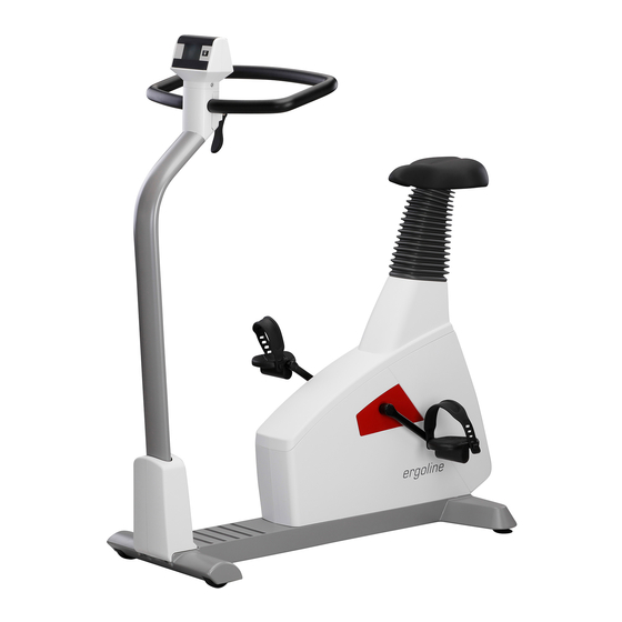
Sockets for power cord and connection cables (underside of ergometer) Power switch (toggle switch [ I / 0 ]) Saddle adjustment with clamping lever Figure 4 – 1: ergoselect 4 M Control terminal T Speed readout for patient Connectors (e.g., for blood pressure cuff, SpO2) -
Page 12: Transport
Extend the foot concerned until the ergometer no longer wobbles. Figure 4 – 4: Levelling feet of the ergoselect ergometer In case of delicate flooring, it is recommended to place a mat under the ergometer to protect the flooring from damage by the feet. ergoselect 4/5... -
Page 13: Mounting The Control Terminal
• Equipment Damage • Before connecting the ergometer to the power line, check that the line voltage corresponds to the ratings on the type plate. The type plate is located on the back of the ergometer, at the bottom. ergoselect 4/5... - Page 14 Pressing the power switch or removing the power cord discon nects the device from the power supply. Removing the power cord results in a complete disconnection of the device from the power supply (all poles). Ensure that the power plug is readily accessible at all times. ergoselect 4/5...
-
Page 15: Connecting The Ecg Cable
Use only connection cables approved by ergoline. A special PC driver software, which can be obtained from ergoline, is required for operation via the USB port. 4.7 Connecting ECG Leadwires Plug the ECG leadwires (L, R, N) into the appropriate sockets (1) in the control terminal. -
Page 16: Connecting The Blood Pressure Cuff
Insert the index finger into the SoftTip sensor. The cable should run over the back of the hand. Within a few seconds the current oxygen saturation in percent (%) will be indicated on the display. Figure 4 – 14: SpO2 SoftTip ergoselect 4/5... -
Page 17: Preparing The Patient For Blood Pressure Measurements
Before applying the cuff, check the position of the micro- phone inside the red pocket (on the inside of the cuff): When the microphone is inside the pocket, its metal side must face the arm. Figure 5 – 3: Correct microphone position ergoselect 4/5... -
Page 18: Applying The Cuff
A loose cuff would degrade the accuracy of the measurement. the cuff tubing from the control terminal. Therefore, the computer aborts the measurement, if a mini The same measures are recommended, if the cuff does not mum pressure is not attained within a few seconds. deflate correctly. ergoselect 4/5... -
Page 19: Operation
• Lubricate the thread of the saddle clamping lever periodi folding it down. cally with a suitable lubricant (e.g., OKS470). The handlebar is not designed to support the full body weight. ergoselect 4/5... -
Page 20: Saddle Adjustment
Figure 6 – 5: Saddle adjustment at the display 1 Saddle up 2 Saddle down Note Press the [ Saddle ] or the key to enable the adjustment of the saddle: the adjustment keys will be displayed (or via the buttons on the control terminal). ergoselect 4/5... -
Page 21: Control Terminal M
Ergometers with the control terminal M support the fol- lowing operating mode: PC Mode An external device (e.g., an ECG recorder, a PC-based ECG system) controls the ergometer – no intervention at all is required at the ergometer. ergoselect 4/5... - Page 22 3 duration of exercise test (min) 4 heart rate at the time of the BP measurement (BPM) 5 pedal speed (RPM) Note • During an exercise test, the saddle height can be adjusted with Figure 7 – 5: Display during exercise test 2 ergoselect 4/5...
-
Page 23: Control Terminal P
A measurement in progress can be aborted with the same key. The functions of these three softkeys chan ge Figure 8 – 3: Keypad P with the displayed menu – the key label describing the function is shown on the display. ergoselect 4/5... -
Page 24: Operating Modes With Control Terminal P
PC Mode and confirm the selection with Select. Figure 8 – 4: Main Menu The display changes – the ergometer is waiting for com- mands from the external ECG unit. Figure 8 – 5: Start screen ergoselect 4/5... -
Page 25: Ergometry
• Additional blood pressure measurements can be initiated with 8.2.2 Ergometry Use the softkeys on the right and on the left (↑ ↓) to position the bar cursor on Ergometry and confirm the selection with Select. Figure 8 – 8: Main Menu ergoselect 4/5... - Page 26 Figure 8 – 11: Screen display during the test Note • The saddle height can be adjusted during an exercise test. • To activate the saddle height adjustment, press the arrow keys will be displayed then. • Additional blood pressure measurements can be initiated with ergoselect 4/5...
-
Page 27: Manual
The exercise test can be terminated manually at any time with the End key located in the middle. The load will immediately drop to 0 watt. There is no recovery phase in the manual mode. Figure 8 – 15: Screen display during the test ergoselect 4/5... -
Page 28: Settings With Control Terminal P
Figure 8 – 19: Selecting the exercise test protocol to edit Use the softkeys on the right and left (↑ ↓) to position the bar cursor on the protocol to change (No. 6 – 15) and confirm the selection with Select. ergoselect 4/5... - Page 29 Here you determine the increments for each load change. Depending on your choice, each key press will change the load by +/– 1, 5, 10 und 25 Watts. Figure 8 – 23: Selecting the increment for manual load changes ergoselect 4/5...
- Page 30 Then the value displayed in reverse video can be edited with the ↑ ↓ keys and saved with Select. The time is adjusted in the same way. You exit the configuration with Figure 8 – 26: Setting the date Figure 8 – 27: Setting the day ergoselect 4/5...
- Page 31 ECG unit. The selection is part of the installation procedure. • The “Analog/Digital” and “Digital” communication is only possible when PC Mode is selected from the main menu or when this is the default mode. ergoselect 4/5...
- Page 32 651 – 750 108 – 115 751 – 850 118 – 125 851 – 950 > 125 951 – 999 > 130 Pulse Display The pulse readout on the display can be turned off. Figure 8 – 31: Setting the Pulse Display ergoselect 4/5...
-
Page 33: Control Terminal T
Figure 9 – 1: Control Terminal T The ergometer runs a self-test. Subsequently, the main menu displays. Figure 9 – 2: Self-test screen The ergometer software is controlled from the touch panel. Figure 9 – 3: Main Menu ergoselect 4/5... -
Page 34: Operating Modes With Control Terminal T
Manual The ergometer is controlled manually, i.e., the user per- forms all load changes via the touch panel. Figure 9 – 7: Operating mode „Manual“ Setup Used to configure the ergometer. Figure 9 – 8: Operating mode „Setup“ ergoselect 4/5... -
Page 35: Pc Mode
You can change the vacuum intensity between low, medi- um and high by touching the [ I ] key. To switch off the pump, press the [ 0 ] key for about 3 seconds. Figure 9 – 10: ECG screen Confirm all inputs with the [ ] key. ergoselect 4/5... -
Page 36: Ergometry
• the basic load (from 6 to 100 W), • the stage time (form 1 to 30 min), • the stage rate (increment, from 1 to 400 W). Figure 9 – 13: Exercise test protocol 2 ergoselect 4/5... - Page 37 To change the load, press the [ + 5 W ] and [ – 5 W ] keys (the increments can be configured from +/– 1 W up to +/– 25 W as needed). See section 9.2.5 “Setup with Control Terminal”, section “Load Change” on page 41. Figure 9 – 16: Starting an exercise test ergoselect 4/5...
-
Page 38: Training / Test
Figure 9 – 18: Terminating an exercise test 2 9.2.3 Training / Test Ten different protocols are available in the Training/Test menu. To edit the protocol parameters, first touch the Training/ Test protocol you want to edit. Figure 9 – 19: Training/Test setup ergoselect 4/5... - Page 39 With the [ ] key (arrow up, [ 1. ] or [ 2. ], you return to the previous screen. Inputs are confirmed with the [ ] key. Figure 9 – 22: Modify parameters 2 ergoselect 4/5...
-
Page 40: Manual
To access a menu, touch the corresponding key on the display. Confirm inputs with the [ ] key and exit menus with the [ ] key. Figure 9 – 25: Setup menu ergoselect 4/5... - Page 41 Figure 9 – 28: Protocol configuration 2 To change the name of a protocol, touch the name and enter the new name from the keypad. Confirm your inputs with the [ ] key. Figure 9 – 29: Protocol configuration 3 ergoselect 4/5...
- Page 42 To prevent an accidental change, this setting is protected with a password. A submenu opens when you touch EKG Type on the display. Enter the code number “3” via the numeric keypad and confirm with the [ ] key. Figure 9 – 32: Setup menu ergoselect 4/5...
- Page 43 No digital data will be sent. Choose the appropriate communication mode and confirm with the [ ] key. Load Change With this function, you select the increments for load changes. Figure 9 – 34: Load change setup ergoselect 4/5...
- Page 44 Touch the respective fields to adjust date and time. Enter day, month, year as well as hours, minutes and seconds via the numeric keypad. Inputs are confirmed with the [ ] key. Figure 9 – 37: Date/Time setup 1 Figure 9 – 38: Date/Time setup 2 ergoselect 4/5...
- Page 45 In this menu, you determine the limits for the RPM indica- tion. The three LEDs on the control panel show the patient whether the pedal speed is high, low or correct. Figure 9 – 41: RPM setup 1 ergoselect 4/5...
- Page 46 Figure 9 – 43: Beep setup Software Version This menu shows the software version and the date of the technical inspection of the measuring system (MTK). Figure 9 – 44: Software Version setup ergoselect 4/5...
- Page 47 Press the [ 2. ] key to display the next screen and touch Display. Figure 9 – 46: Setup screen 1 Switch the pulse readout on or off. Select the blood pressure unit: mmHg (millimeter of mercury) or kPa (kilopascal). Figure 9 – 47: Setup screen 2 ergoselect 4/5...
-
Page 48: Cleaning, Maintenance, Disposal
B. Braun Melsungen AG: • Hexaquart plus ® (0,5 % / 5,0 %) • Hexaquart S ® (1,5 % / 5,0 %) • Meliseptol ® • Melsept SF ® (0,5 % / 5,0 %) ECOLAB: • Incidin Foam ® ergoselect 4/5... -
Page 49: Cleaning The Blood Pressure Cuff
B. Braun Melsungen AG: • Hexaquart plus ® (0,5 % / 5,0 %) • Hexaquart S ® (1,5 % / 5,0 %) • Meliseptol ® • Melsept SF ® (0,5 % / 5,0 %) ECOLAB: • Incidin Foam ® ergoselect 4/5... -
Page 50: Inserting The Microphone
The product described in this operator manual must not be disposed of as unsorted municipal waste and must be collected separately. Please contact your authorized manufacturer ergoline GmbH for information concerning the disposal of your equipment. There is no waste approval. Proper disposal is documented by ergoline GmbH. -
Page 51: Technical Specifications
11 Technical Specifications 11.1 Ergometer Model modular ergometer system ergoselect 4 / 5 models ergoselect 4, M / P / T, ergoselect 5, M / P / T Operating mode continuous operation Power 100 – 240 V / 50 – 60 Hz (max. - Page 52 +10 to +40 °C rel. humidity 30 to 75 %, no condensation atmospheric pressure: 800 to 1060 hPa transport and storage: temperature: –20 to +70 °C rel. humidity 10 to 95 %, no condensation atmospheric pressure: 500 to 1060 hPa ergoselect 4/5...
-
Page 53: Blood Pressure Module
6 seconds (to 140 mmHg) and approx. 18 seconds (to 300 mmHg) Max. cuff pressure 300 mmHg Cuff deflation method pulse-dependent deflation rate approx. 3 mmHg/beat or approx. 3 mmHg/s Calibration calibration with external pressure meter Artifact rejection automatic artifact rejection ergoselect 4/5... -
Page 54: Exercise Test Protocols
Duration Load Increment Stage Time Recovery Load Recovery Time [sec] [sec] [min] ramping protocol PWC-130 (*) PWC-150 (*) PWC-170 (*) (*) the protocol advances to the recovery phase as soon as the target heart rate (130/150/170) is reached ergoselect 4/5... -
Page 55: Family Of Characteristics Of The Braking Torque Control Range
DIN VDE 0750-0238 black + grey: speed-independent range of the ergoselect ergometer 11.6 Family of characteristics of the load periods according to IEC 60601‑1 Figure 11 – 2: Under permanent load, the load periods and pauses (white) shall be observed. ergoselect 4/5... -
Page 56: Electromagnetic Compatibility En 60601-1-2
12 Electromagnetic Compatibility EN 60601‑1‑2 Changes or modifications to this system not expressly Warning approved by ergoline may cause EMC issues with this or • RF Interference • other equipment. Use of portable telephones or other radio frequency (RF) emitting... - Page 57 EN 61000-4-8 a typical location in a typical com- mercial or hospital environment. The ergoselect ergometer has no components susceptible to magnetic fields. NOTE: UT is the a.c. mains voltage prior to application of the test level. ergoselect 4/5...
- Page 58 If abnormal performance is observed, additional measures may be necessary, such as re-orienting or relocating the ergoselect ergometer. (b) Over the frequency range from 150 kHz to 80 MHz, field strengths should be less than 3 V/m. ergoselect 4/5...
- Page 59 NOTE 1: At 80 MHz and 800 MHz, the higher frequency range applies NOTE 2: These guidelines may not apply in all situations. Electromagnetic propagation is affected by absorption and reflection from structures, objects, and people. ergoselect 4/5...
- Page 60 201000433000 • Version 2017-01-12 / Rev 01 • English ergoselect 4/5...
- Page 62 GmbH Lindenstraße 5 72475 Bitz Germany Tel.: +49‑(0) 7431 98 94 ‑ 0 Fax: +49‑(0) 7431 98 94 ‑ 128 e‑mail: info@ergoline.com http: www.ergoline.com...
Need help?
Do you have a question about the ergoselect 4 and is the answer not in the manual?
Questions and answers
Dear Ergoline, I want to inquire if egoslect 4 comes with ECG software and the connecting cable? Looking forward to your prompt and kind response
The Ergoline Ergoselect 4 requires a special PC driver software for operation via the USB port, which can be obtained from Ergoline. It also specifies the use of approved connection cables. However, it does not explicitly state that the ECG software and connecting cable are included with the device.
This answer is automatically generated