Table of Contents
Advertisement
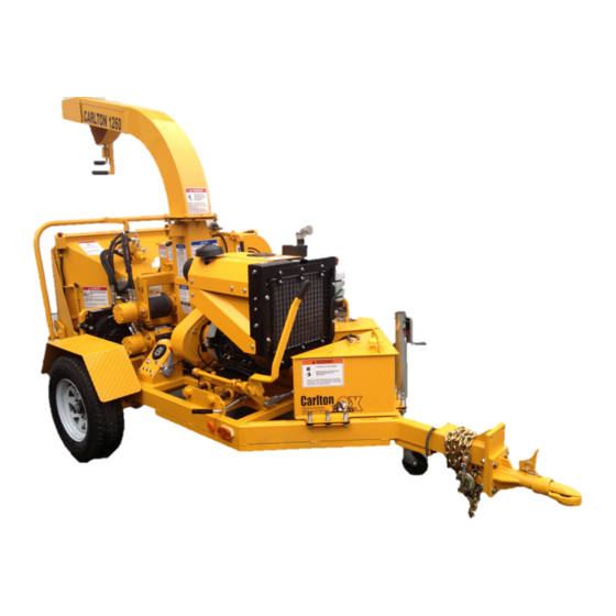
6" Disk Style Brush Chippers
Machine Serial #
Engine Model & Spec #
Engine Serial #
PTO/Clutch Model & Spec #
Clutch Serial #
Purchase Date
Dealer
Carlton
J.P.Carlton Company
Div. D.A.F. Inc.
121 John Dodd Road
Spartanburg, SC 29303
Ph. (864) 578-9335
Fax (864) 578-0210
www.stumpcutters.com
Model 1260
_____________
_____________
_____________
_____________
_____________
_____________
_____________
Advertisement
Table of Contents

Related Manuals for Carlton 1260


Summary of Contents for Carlton 1260
- Page 1 6” Disk Style Brush Chippers Model 1260 Machine Serial # _____________ Engine Model & Spec # _____________ Engine Serial # _____________ PTO/Clutch Model & Spec # _____________ Clutch Serial # _____________ Purchase Date _____________ Dealer _____________ Carlton J.P.Carlton Company Div. D.A.F. Inc.
- Page 3 DIESEL ENGINE EXHAUST WARNING CALIFORNIA Proposition 65 Warning Diesel engine exhaust and some of its constituents are known to the State of California to cause cancer, birth defects, and other reproduction harm.
- Page 5 CHIPPER SAFETY ALERT...
- Page 7 CHIPPER SAFETY ALERT...
- Page 9 CHIPPER SAFETY ALERT...
- Page 11 CHIPPER SAFETY ALERT...
- Page 13 CHIPPER SAFETY ALERT...
- Page 15 CHIPPER LIMITED WARRANTY J. P. Carlton Co. Inc., hereafter referred to as the “Manufacturer”, warrants each new Carlton Chipper to be free of defects in workmanship and material for a period of one year. This warranty takes effect upon delivery to the original retail purchaser. The manufacturer at its option will replace or repair at a point designated by the manufacturer, any parts which appear to have been defective in material or workmanship.
- Page 17 The manufacturer will provide replacement parts at no cost to the customer for defective parts during the warranty period. Defective parts must be returned to J. P. Carlton Company. It will be the customer’s responsibility to install the replacement parts unless arrangements are made with the selling dealer.
- Page 19 11. _________ Customer has been advised that maintenance and adjustment on the clutch are critical. Customer has been advised that J. P. Carlton Co. does not warrant the clutch and the only warranty that applies is in the clutch manufacturer’s manual. Contact the clutch manufacturer with warranty issues.
-
Page 21: Table Of Contents
6” CHIPPER TABLE OF CONTENTS INTRODUCTION FOREWORD GENERAL INFORMATION MACHINE FEATURES MACHINE SPECIFICATIONS OPERATION SAFETY PRECAUTIONS DAILY CHECKLIST MACHINE CONTROLS TOWING GUIDE MACHINE OPERATION MAINTENANCE MACHINE MAINTENANCE LUBRICATION TROUBLESHOOTING GUIDE SERVICING HYDRAULICS SERVICING CUTTER SYSTEM SERVICING BELTS SERVICING FEED WHEEL MOTOR MACHINE WIRING PARTS DECAL ASSEMBLY... -
Page 23: Foreword
6” CHIPPER FOREWORD Congratulations on your purchase of a new Carlton Professional Chipper! Carlton has built ® ® its reputation on the superior performance and reliability of their stump grinders and you can be assured your new chipper has the same performance and reliability. A machine is not profitable if it’s broken-down and we do our absolute best to help you avoid costly downtime. -
Page 24: General Information
Any reference made to the right, left, front, or rear in relationship to the chipper is illustrated in the following pictures. Please refer to these any time you call your dealer or J. P. Carlton for parts or assistance. -
Page 25: Machine Features
6” CHIPPER MACHINE FEATURES Available Machine Features: • 35 HP gas engine • Front jack stand – • Top feed roller – • Auto-Feed 7000# Cap, Screw type 10 1/2” x 12” Plus ® • AR400 anvil • Bottom feed roller – system •... -
Page 26: Machine Specifications
6” CHIPPER MACHINE SPECIFICATIONS General: Hydraulic System: Weight: ---------------- 3000 Pounds Hyd Pump Displcmnt: .329 in cu/rev Length: ----------------- 132 inches Hyd Pump Drv Systm: Direct Drive off Engine Mount Height: ----------------- 89 inches Flow: -------------------5.33 GPM Tires: ------------------- 205/75R14 Ld Rng C 1760 # System Relief: ---------2500 PSI @ 50 PSI Oil Tank Capacity: ---8 Gallons... - Page 27 6”CHIPPER SAFETY PRECAUTIONS Before operating the chipper, read this manual, the engine manual, and all the safety decals on the machine. Know all parts of the machine and their functions, especially the shut down procedures in case of emergency. No inexperienced person may operate the chipper. Inexperience may cause injury.
-
Page 28: Operation
(prescription, over the counter, or • Never position, adjust, or move the otherwise). discharge chute while the chipper or • DO NOT modify or change any part the cutter disk are running without written approval from J. P. Carlton Company. - Page 29 6”CHIPPER SAFETY PRECAUTIONS • Always have at least 2 operators at the job site running the chipper. One to load the brush into the feed wheels and the other to maintain the feed control bar in case of an accident. •...
- Page 30 6”CHIPPER SAFETY PRECAUTIONS DO NOT PERFORM MAINTENANCE OF ANY KIND ON THIS MACHINE UNLESS: The engine is turned off The ignition key is removed Positive battery cable is disconnected The clutch is disengaged • YOKE LOCK PIN MUST BE IN Feed control bar is in neutral POSITION before performing All machine parts have come to a...
- Page 31 Decals may be purchased from J. • Keep unauthorized persons away from P. Carlton or an authorized dealer. • the chipper operation area. Remove all foreign objects from the chipper...
- Page 32 6” CHIPPER DAILY CHECKLIST It is vital that the owner and operators inspect the chipper each day before operation. This inspection will help identify potential problems that may arise during the workday. The operators must get in the habit of performing this inspection each and every day. By performing this inspection each day, the operators will help minimize downtime and costly repairs.
-
Page 33: Daily Checklist
6” CHIPPER DAILY CHECKLIST • Make sure all personnel are equipped with all applicable safety equipment: − Eye protection − Hearing protection − Hard hat − Short, fitted gloves − Long sleeve shirt − Long pants − Over the ankle work boots with skid resistant soles PERSONAL PROTECTION: All personnel must wear eye and... - Page 34 6” CHIPPER DAILY CHECKLIST • Check air pressure in tires daily. Inflate to tire manufacturers recommended maximum inflation pressure for temperature and climate. • Inspect tires for wear. • Inspect axle caps, replace if necessary. Grease axles as suggested by manufacturer.
- Page 35 6” CHIPPER DAILY CHECKLIST • Inspect cutter disk knives and anvil for wear. Do not operate the machine without a full set of undamaged knives in place. Worn or chipped knives will cause improper operation of the chipper. (See Servicing Cutter Disk Section to change or sharpen knives and anvil.) CHIPPED KNIFE •...
- Page 36 6” CHIPPER DAILY CHECKLIST ENGINE OIL DIPSTICK LOCKABLE TANKS • Check and maintain proper engine oil, fuel tank, and hydraulic oil tank levels. Make sure engine is cool before checking. Replenish engine oil, fuel, and hydraulic oil every morning before starting the machine so there is no danger of fire from hot machine parts or sparks.
- Page 37 6” CHIPPER MACHINE CONTROLS It is imperative that all operators are familiar with all controls of the chipper. This will make for a much more productive and safer work period. (The actual controls may differ depending on the engine supplied with your chipper.) ENGINE CONTROLS: •...
-
Page 38: Machine Controls
6” CHIPPER MACHINE CONTROLS ENGAGEMENT HANDLE & ENGINE SLIDE LOCK • The cutter disk is disengaged when the engagement handle is pushed forward and the engine slide lock is in the locked position. • After disengaging the cutter disk, allow several minutes for the disk to come to a complete stop before performing any maintenance or service to the machine, even... - Page 39 ADJUST THIS FLAP WHILE THE CHIPPER IS IN OPERATION OR WHILE THE CHIPPER DISK IS SPINNING! SWIVEL DISCHARGE • Carlton Chippers are equipped with a rotating discharge chute. To rotate the chute to the desired position 1. Pull down and unlock the rotation lock pin.
- Page 40 6” CHIPPER MACHINE CONTROLS FEED CONTROL BAR • The feed control bar is located on three sides of the infeed chute; across the top and down each side. • The feed control bar has three distinct positions In the out position pulled towards the rear −...
- Page 41 6” CHIPPER MACHINE CONTROLS FEED WHEEL CLEAN OUT DOOR • There is a drop-down door to clean excess debris out from under the bottom feed wheel. This will help to keep the chipper from getting clogged or stopped up. Use the handle, located under the infeed chute, and drop the door down to remove debris, then close and secure the door.
-
Page 42: Towing Guide
6” CHIPPER TOWING GUIDE SAFETY: • NEVER ALLOW INEXPERIENCED DRIVERS TO TOW MACHINERY. • ALWAYS MAKE SURE THE TRUCK HITCH AND THE CHIPPER HITCH ARE OF MATCHING STYLE AND SIZE. • ALWAYS MAKE SURE THE TOW VEHICLE AND THE CHIPPER ARE ON LEVEL GROUND AND THE WHEELS ARE CHOCKED BEFORE CONNECTING OR DISCONNECTING THE CHIPPER. - Page 43 6” CHIPPER TOWING GUIDE • Connect chipper lights to the tow vehicle. Observe light operation to insure correct electrical connections. • Secure the jack stand to the machine for towing. • The chipper infeed tray must be closed and locked when towing. •...
- Page 44 6” CHIPPER TOWING GUIDE • Make sure the discharge chute is over the chipper front for towing. Position the deflector, on the end of the discharge chute, down when towing to reduce the chance of debris flying out of the chute. •...
-
Page 45: Machine Operation
6” CHIPPER MACHINE OPERATION STARTING – READ THIS MANUAL, THE ENGINE OWNERS’ MANUAL, THE CLUTCH MANUAL, AND ALL SAFETY DECALS ON CHIPPER BEFORE STARTING. SAFETY: • DO NOT ALLOW CHILDREN OR OTHER SPECTATORS TO STAND AND WATCH THE CHIPPER IN OPERATION. ALL OPERATORS MUST WEAR RECOMMENDED PROTECTIVE EQUIPMENT. - Page 46 6” CHIPPER MACHINE OPERATION LOWER THE INFEED TRAY • During transportation the infeed tray will be closed and locked using the spring lock pins attached. At the job site, pull the pins in and lower the tray. SPRING LOCK PIN •...
- Page 47 6” CHIPPER MACHINE OPERATION AIM DISCHARGE CHUTE • Carlton Chippers are equipped with a rotating discharge chute. To rotate the chute to the desired position 1. Pull down and unlock the rotation lock pin. 2. Use the handle on the end of the...
- Page 48 6” CHIPPER MACHINE OPERATION START ENGINE • The Key Switch is located on the Vanguard engine. • Key switch has 3 positions Stop, Run and Start • Start engine at idle speed and allow sufficient time for oil to circulate before proceeding.
- Page 49 6” CHIPPER MACHINE OPERATION TURN AUTO-FEED PLUS ON • The Auto-Feed Plus® monitors the engine RPM and controls the feed system based on this information. The Auto-Feed® is calibrated when installed in the chipper with a high and low RPM setting for the feed wheels to operate.
- Page 50 6” CHIPPER MACHINE OPERATION INCREASE ENGINE SPEED • Once the cutter disk has been fully engaged, the engine can be run at full speed. Use the throttle to increase engine speed. • The engine should always be run at high RPM while material is being chipped.
- Page 51 6” CHIPPER MACHINE OPERATION • If a tree gets jammed and has to be trimmed, shut down the chipper. • Always feed trees and brush walking to the right side of the chipper, material being fed should be to the operators’ left side.
- Page 52 6” CHIPPER MACHINE OPERATION • Keep an eye on the surrounding area and don’t allow anyone to come up too close to the chipper or to be in the chip discharge area. Maintain a clear area of at least 100 ft. in every direction around the chipper.
- Page 53 6” CHIPPER MACHINE OPERATION • Once the engine has had time to slow down to idle, disengage the cutter disk by pushing the engagement handle forward as far as it will go. Make sure the engine slide lock is in position to prevent the cutter disk accidentally being engaged.
- Page 54 6” CHIPPER MACHINE OPERATION • Secure the discharge chute. Pull down the spring lock pin and use flap adjustment handle to position the chute over the chipper front. When discharge is in position, release the pin in the closest groove to lock. Make sure the discharge chute is locked in position.
-
Page 55: Machine Maintenance
6” CHIPPER MACHINE MAINTENANCE DO NOT PERFORM MAINTENANCE OF ANY KIND ON THIS MACHINE UNLESS: The engine is turned off The ignition key has been removed The positive battery cable has been disconnected The engine slide assembly is in the disengaged position and the engine slide stop is locked The feed control bar is in neutral All machine parts have come to a complete stop –... - Page 56 Refer to engine manual supplied with your chipper. • Check fuel level daily and replenish as necessary. Carlton chipper fuel tanks are equipped with lockable cap covers. FUEL FILTER Replace the fuel filter every 500 hours of operation or 6 months.
- Page 57 • Before starting to chip any wood, always test the feed control bar. Make sure the reverse, stop, and forward feed positions work properly. • Contact Carlton or an authorized dealer immediately if the control bar doesn’t work properly in any of the three positions.
- Page 58 6” CHIPPER MACHINE MAINTENANCE HITCH • Make sure the bolts on the chipper hitch are tightened. Torque the 5/8” bolts and nuts to 230 ft.-lbs. Also, make sure the hitch bolts on the tow vehicle are tightened properly. • Check the bolts and nuts for wear. If bolt or nut threads are chipped or worn down, or if the bolts and nuts won’t stay tight after tightening them, the bolts and...
- Page 59 6” CHIPPER MACHINE MAINTENANCE JACK STAND – FRONT • Check the lock pins to make sure they JACK STAND are fitting properly and in good shape. Replace any pins that are worn, bent or damaged in any way. • Check general condition of the jack stand.
-
Page 60: Lubrication
6” CHIPPER LUBRICATION • All of Carlton’s machines are built to be • Below you will find a Lubrication rugged performers. Our design goals are Schedule that will give you the sturdiness, simplicity and reliability. recommended frequency for lubrication. • A regularly scheduled maintenance •... - Page 61 6” CHIPPER LUBRICATION CHIPPER – LEFT SIDE EQUIPPED WITH DEXTER AXLES, EITHER E-Z LUBE® OR NEV-R-LUBE® – SEE CUTTER DISK BEARING DEXTER INFORMATION GREASE FITTING ENCLOSED IN MANUAL * PURGE BEARINGS DAILY, UNTIL NEW GREASE IS SEEN FEED CONTROL BAR GREASE FITTING * GREASE AS NECESSARY EVERY 30-40 HOURS OF...
- Page 62 6” CHIPPER LUBRICATION CHIPPER – RIGHT SIDE CUTTER DISK BEARING SWIVEL PLATES GREASE FITTING GREASE FITTING * PURGE BEARINGS * GREASE EVERY 3 DAILY, UNTIL NEW MONTHS AS NEEDED GREASE IS SEEN LIFT BEARING GREASE FITTING * 2 PUMPS OF GREASE WEEKLY ON EACH BEARING EQUIPPED WITH DEXTER...
- Page 63 6” CHIPPER TROUBLESHOOTING GUIDE DO NOT PERFORM ANY INSPECTION OR SERVICE ON THE CHIPPER WITHOUT MAKING SURE: THE CUTTER DISK IS DISENGAGED AND HAS COME TO A COMPLETE STOP; THE CUTTER DISK LOCK PIN IS INSTALLED; THE ENGINE HAS BEEN TURNED OFF, THE IGNITION KEY HAS BEEN REMOVED AND THE BATTERY CABLE HAS BEEN DISCONNECTED;...
-
Page 64: Troubleshooting Guide
6” CHIPPER TROUBLESHOOTING GUIDE COMPLAINT CAUSE CORRECTION • • Auto-Feed not working Faulty or broken wiring Repair or replace wires – properly or at all wiring diagram enclosed in this manual • Settings not correct • Reset following Auto-Feed manual instructions enclosed in this manual •... -
Page 65: Servicing Hydraulics
Allow system to warm up too low • Pump has excessive wear • Replace pump Any other problems contact your local dealer or J. P. Carlton Co. ONLY USE QUALIFIED PERSONNEL TO WORK ON HYDRAULIC SYSTEMS FOR REPAIRS OR REPLACEMENT OF PARTS!! - Page 66 CARDBOARD; DO NOT USE HAND OR FINGER. ALWAYS WEAR EYE PROTECTION. HYDRAULIC OIL & FILTER • This Carlton chipper has an in-tank hydraulic filter and a level/temp gauge. Check hydraulic oil daily, before and during use. Use AW-32 hydraulic oil same as supplied by the manufacturer.
- Page 67 SERVICE HYDRAULICS • Check hydraulic oil level daily. This Carlton chipper is equipped with a gauge that shows the level of oil and the temperature of the oil. When filling the tank with oil, the window of the gauge will also fill with oil, as the level gets higher in the tank.
- Page 68 • The overall pressure setting is 2500 PSI, set at the factory. Do not adjust the pressure setting. If you feel the pressure needs adjusting, contact JP Carlton or you local Carlton dealer. ONLY USE QUALIFIED PERSONNEL TO WORK ON HYDRAULIC SYSTEMS...
- Page 69 6” CHIPPER SERVICE CUTTER SYSTEM DO NOT PERFORM MAINTENANCE OF ANY KIND ON THIS MACHINE UNLESS: The engine is turned off The ignition key has been removed The positive battery cable has been disconnected The engine slide assembly is in the disengaged position and the engine slide stop is locked The feed control bar is in neutral All machine parts have come to a complete stop –...
- Page 70 • Knife bolts are of a particular design and nuts are security lock nuts. DO NOT USE ANY OTHER STYLE OF CUTTER DISK LOCK PIN IN LOCKED POSITION BOLTS AND NUTS. You must purchase these bolts and nuts from Carlton or an authorized dealer.
- Page 71 • Improper sharpening may affect knives hardness resulting in knife failure. • If knives are too narrow to grind, replace with a complete set of new knives. • Knives are hardened steel made to Carton’s specifications. Use only Carlton chipper knives as replacements.
- Page 72 6” CHIPPER SERVICE CUTTER SYSTEM • Reassemble knives in the pocket making sure they seat flat. • Tighten knife bolts and torque the nuts to 90 ft. lbs. • Do not over tighten knife bolts. Torque only to the recommended amount. Knives that are overly tight can crack or bow around the hole.
- Page 73 6” CHIPPER SERVICE CUTTER SYSTEM • Inspect the anvil working edge for wear or damage before you check the clearance. If the anvil needs to be changed to a new work surface or to be replaced, follow the instructions in Anvil Replacement later in this section.
- Page 74 6” CHIPPER SERVICE CUTTER SYSTEM • If clearance needs to be adjusted, loosen the anvil bolts; just loose enough to be able to move the anvil with the adjuster bolts. • Loosen the nuts on the adjustment bolts that are on the far side of the plate (as shown).
-
Page 75: Servicing Cutter System
6” CHIPPER SERVICE CUTTER SYSTEM • After clearance has been set and all bolts and nuts have been tightened properly, remove the yoke lock pin and put it back in its holder. REMOVE YOKE LOCK PIN AND RETURN TO HOLDER LOWER THE UPPER FEED WHEEL USING THE JACK... - Page 76 KNIVES PART NO DESCRIPTION 0900114 Knife – 1/2” x 4” x 7 1/4” 1/2” Knife Bolt – Special Design – Purchase from 0900124Z JP Carlton or Dealer 1/2” Security Lock Nuts – Purchase from JP 0900126 Carlton or Dealer...
- Page 77 • The anvil is hardened steel made to Carton’s specifications. Use only Carlton anvils as replacements or damage may occur. Purchase the new anvil from Carlton or an authorized dealer. THE ANVIL HAS FOUR WORKING EDGES. TWO OF THESE EDGES ARE SHOWN ABOVE. FLIP THE ANVIL...
- Page 78 6” CHIPPER SERVICE CUTTER SYSTEM • To rotate to a new edge or to replace the anvil, remove the anvil bolts and adjuster bolts. There are three anvil bolts, two with adjuster bolts attached. • First, remove the nut on the outside of each adjuster bolt and loosen the inside nut.
- Page 79 6” CHIPPER SERVICE CUTTER SYSTEM • A setscrew must always be in the hole next to the working edge to keep debris out of the hole (see picture at right). Insert the setscrew on the handle side of the anvil to prevent clogging the wrench slot.
- Page 80 6” CHIPPER SERVICE CUTTER SYSTEM • Tighten the anvil bolts loosely. Put a flat washer and a nut back on the outside of each adjuster bolt. Do not tighten the nut until clearance has been set. • ALWAYS CHECK & SET KNIFE TO ANVIL CLEARANCE AFTER REMOVING AND REPLACING KNIVES OR ANVIL.
- Page 81 • If any problems are discovered, contact Carlton or your local dealer for repair or replacement. NO GAPS OR OPENINGS THE CUTTER DISK HOOD IS ONE OF...
- Page 82 6” CHIPPER SERVICE BELTS AND SHEAVES DO NOT PERFORM MAINTENANCE OF ANY KIND ON THIS MACHINE UNLESS: The engine is turned off The ignition key has been removed The positive battery cable has been disconnected The engine slide assembly is in the disengaged position and the engine slide stop is locked The feed control bar is in neutral All machine parts have come to a complete stop –...
- Page 83 6” CHIPPER SERVICE BELTS AND SHEAVES • ENGINE MUST BE OFF AND IGNITION KEY REMOVED BEFORE CHECKING BELT TENSION. • ALL PARTS MUST BE COMPLETELY STOPPED. • THE CUTTER DISK LOCK PIN MUST BE INSTALLED IN THE DISK LOCK TUBE. BELT ENGAGED •...
- Page 84 6” CHIPPER SERVICE BELTS AND SHEAVES ADJUST BELT TENSION • If belt tension needs to be adjusted, the clevis on the engine slide must be adjusted. JAM NUT CLEVIS • The belt must be disengaged. Disengage BELT ENGAGED belt by pushing the engagement handle forward till the engine slide stop goes back into position.
- Page 85 6” CHIPPER SERVICE BELTS AND SHEAVES • If belt tension is too tight, relieve the excess tension by performing the same procedure except turn the clevis clockwise to shorten the linkage and reduce belt tension. Always make slight adjustments and then recheck tension. •...
- Page 86 6” CHIPPER SERVICE BELTS AND SHEAVES CHECK BELT GUARD • Check and retighten bolts daily. • Check condition of bolt and nut threads when belt guards are removed or if a bolt won’t tighten or won’t stay tightened. • Replace any bolts or nuts that are worn or damaged.
- Page 87 6” CHIPPER SERVICE BELTS AND SHEAVES • Belt should be disengaged. If it isn’t, BELT DISENGAGED disengage by pushing the engagement handle forward till the engine slide stop goes back into position. Engine slide must be locked when the belt is disengaged.
- Page 88 6” CHIPPER SERVICE BELTS AND SHEAVES • When just replacing the belt, it will not be necessary to check sheave alignment. The belt engagement adjustment is a straight and parallel operation that will not take sheaves out of alignment. • Go back to the BELT TENSION section and check and adjust belt tension.
- Page 89 6” CHIPPER SERVICE BELTS AND SHEAVES REPLACING SHEAVE OR BUSHING • If it becomes necessary to replace a sheave or bushing, replace only one at a time. Never remove both sheaves at the same time. • This section covers removing and replacing the cutter disk sheave.
- Page 90 6” CHIPPER SERVICE BELTS AND SHEAVES • Replace bolts in the sheave and tighten lightly. • Check the mark you made earlier next to the bushing. If bushing was not moved in replacing the sheave, tighten screws. • If bushing is replaced or moved on the shaft, realign the sheaves using a 2-foot straight edge across the engine and cutter disk sheaves.
- Page 91 There is a special tool required to separate the motor and coupling once it is off the machine, contact J. P. Carlton or your local dealer to purchase the puller. CHANGE MOTORS ONE AT A TIME. • The following instructions are for the...
- Page 92 6” CHIPPER SERVICE FEED WHEEL MOTOR WARNING: RELEASE HYDRAULIC PRESSURE BEFORE PERFORMING ANY SERVICE TO HYDRAULIC LINES OR OTHER COMPONENTS. FLUID UNDER PRESSURE CAN PENETRATE THE SKIN AND CAUSE SEVERE INJURY. SEEK IMMEDIATE MEDICAL ATTENTION IF SKIN IS PENETRATED. CHECK HOSES AND FITTINGS USING A BOARD OR CARDBOARD;...
- Page 93 • There is a special tool required to separate the motor and coupling once it is off the machine, contact J. P. Carlton or your local dealer to purchase the puller. • Attach the separating tool to the coupler as shown and screw the three bolts from the bushing into the tool in the outside holes.
- Page 94 6” CHIPPER SERVICE FEED WHEEL MOTOR • Replace with new motor. Clean the threads on the motor, the 1” nut, and the coupling with degreaser before beginning to replace all the parts. • Attach the torque arm to the new motor using the 1/2”...
- Page 95 6” CHIPPER SERVICE FEED WHEEL MOTOR • Return the feed wheel motor assembly to the machine and tighten the bolts in the bushing. Tighten each bolt a little at a time to pull the coupling into place as straight as possible. Try not to pull one side on faster than the other or damage may occur to the bushing and the coupling.
-
Page 96: Machine Wiring
6” CHIPPER MACHINE WIRING CHIPPER WIRING DIAGRAM – VANGUARD ENGINE WIRING MAY BE DIFFERENT DEPENDING ON ENGINE SUPPLIED WITH THE CHIPPER. SEE THE ENGINE OWNER’S MANUAL FOR THE ENGINE WIRING DIAGRAM... - Page 97 6” CHIPPER MACHINE WIRING CHIPPER WIRING DIAGRAM – DEUTZ ENGINE WIRING MAY BE DIFFERENT DEPENDING ON ENGINE SUPPLIED WITH THE CHIPPER. SEE THE ENGINE OWNER’S MANUAL FOR THE ENGINE WIRING DIAGRAM...
- Page 98 6” CHIPPER MACHINE WIRING CHIPPER WIRING DIAGRAM – KUBOTA ENGINE WIRING MAY BE DIFFERENT DEPENDING ON ENGINE SUPPLIED WITH THE CHIPPER. SEE THE ENGINE OWNER’S MANUAL FOR THE ENGINE WIRING DIAGRAM...
-
Page 99: Decal Assembly
DANGER – FEED WHEEL SERVICE 0700324-1 YOKE LOCK PIN 0700324-2 YOKE LOCK HOLE 0700323-1 DISK/DRUM LOCK TUBE 0700323-2 DISK/DRUM LOCK PIN 0700327 DANGER – FEED HOPPER 0700321_A GREASE DAILY 0700322 SOLID ARROW 0700301 DANGER – MOVING PARTS CARLTON – 1260... - Page 100 MOTOR COUPLER GUARD (2 PLCS) 0700321_A GREASE DAILY 0700322 SOLID ARROW (2 PLCS) 0700301 DANGER – MOVING PARTS 0700320 AUTO-FEED ON/OFF INFO. 0700309 NOTICE – DECAL MAINTENANCE 0700315 WARNING – HEARING/EYE PROTECTION 0700009 PINCH POINTS CARLTON – 1260 CARLTON – PROFESSIONAL TREE EQUIPMENT...
- Page 101 DECAL ASSEMBLY CHIPPER – FRONT ITEM # PART # DESCRIPTION 0700310 NOTICE – HYDRAULICS/LUBRICATION 0700314 WARNING – FROZEN BATTERY 0700311 NOTICE – BELT/BEARING MAINTENANCE 0700319 HYDRAULIC OIL INFO. HYDRAULIC OIL GASOLINE ONLY 0700321_A GREASE DAILY (TYP BOTH SIDES) CARLTON DECAL...
- Page 102 6” CHIPPER DECAL ASSEMBLY CHIPPER – REAR ITEM # PART # DESCRIPTION 0700318 PUSH – REVERSE 0700307 DANGER – INJURY/DEATH DANGER – KEEP CLEAR (ALL RED) 0700060 CARLTON OX DECAL CARLTON – 1260...
- Page 104 WELDMENT,FRAME BUINESS LINE 20610043 WELDMENT,FENDER,LH CHIPPERS 20610044 WELDMENT,FENDER,RH OWNER DOMAIN 20640055 PLATE,AUTOFEED J.P. CARLTON COMPANY DIV. DAF INC. SERIAL NUMBERS 29A-06 NUT,STOVER LOCK, 3/8-16 UNC GR8 1J9U50116E1167160 & UP 30-06 LOCK WASHER,3/8" DESCRIPTION ISSUE 34A-06 FLAT WASHER, 3/8 SAE GR8 AXLE, TIRES AND RIMS Revised 2.20.06...
- Page 105 DESCRIPTION 1 FRAME AND TANKS 20610015 ASSEMBLY,FUEL TANK BUINESS LINE CHIPPERS 20610016 ASSEMBLY,HYDRAULIC TANK OWNER DOMAIN J.P. CARLTON COMPANY DIV. DAF INC. 20610025 ISOLATOR,FUEL TANK SERIAL NUMBERS 1J9UE021871167465 & UP 20610028 ISOLATOR,HYDRAULIC TANK DESCRIPTION ISSUE HYDRAULIC AND FUEL TANK INST.
- Page 106 HEX CAP SCREW,1/2 X 1 NF GR 8 BUINESS LINE 29A-05 NUT,LOCK,5/16-18 GR 8 CHIPPERS OWNER DOMAIN 30A-08 LOCKWASHER 1/2" J.P. CARLTON COMPANY DIV. DAF INC. SERIAL NUMBERS 31A-05 FLAT WASHER, 5/16 USS GRD 5 1J9U50116E1167160 & UP DESCRIPTION ISSUE 31A-08ZI FLAT WASHER 1/2 USS GR 8 Z&Y...
- Page 107 GASKET- BAYONET MOUNT GAS CAP BUINESS LINE 14B-1010 SHCS 10-24 x 1 1/4 UNC GR 8 CHIPPERS OWNER DOMAIN 20610017 WELDMENT,FUEL TANK J.P. CARLTON COMPANY DIV. DAF INC. SERIAL NUMBERS 20610052 WELDMENT,FUEL PICK-UP TUBE 1J9UE021871167465 & UP DESCRIPTION ISSUE 21210156...
- Page 108 STRAINER- TANK MOUNTED LTM-15 BUINESS LINE 0300266A HYDRAULIC SITE GAUGE W/TEMP CHIPPERS OWNER DOMAIN 12D-0612 SHCS 3/8 X 1-1/2 NC GR 8 J.P. CARLTON COMPANY DIV. DAF INC. SERIAL NUMBERS 1J9UE021871167465 & UP 20610018 WELDMEMT,HYDRAULIC TANK DESCRIPTION ISSUE 21210154 BRACKET,VANDADLISM,HYRDRUALIC TANK HYDRAULIC TANK Revised 2.20.06...
- Page 109 2 ENGINE/ELECTRICAL 05506101A BEEHIVE- BRIGGS CHIPPER 14020023 PLATE,ENGINE SEAL,KOHLER/BRIGGS BUINESS LINE CHIPPERS 14020024 MOUNT,CRANK SHAFT HYDRAULIC PUMP OWNER DOMAIN J.P. CARLTON COMPANY DIV. DAF INC. 14020025 BUSHING,ENGINE SEAL SERIAL NUMBERS 1J9U50116E1167160 & UP 20620002 ASSEMBLY,ENGINE SLIDE DESCRIPTION ISSUE 20620008 KEEPER,BELT,REAR ENGINE INSTALL Revised 2.20.06...
- Page 110 PROFESSIONAL TREE EQUIPMENT FUCTION GROUP 2 ENGINE/ELECTRICAL BUINESS LINE CHIPPERS OWNER DOMAIN J.P. CARLTON COMPANY DIV. DAF INC. SERIAL NUMBERS 1J9U50116E1167160 & UP DESCRIPTION ISSUE ENGINE SLIDE ASSEMBLY Revised 2.20.06 DUE TO CONTINUOUS DESIGN IMPROVEMENTS CONSULT FACTORY PRIOR TO ORDERING 1-800-243-9335.
- Page 111 LOCK WASHER,# 10 GR 8 34A-04 WASHER,FLAT 1/4 SAE GR 8 BUINESS LINE CHIPPERS 41E-04 GREASE FITTING 1/4-28 STRAIGHT OWNER DOMAIN J.P. CARLTON COMPANY DIV. DAF INC. 50L-02 SNAP PIN, 1/8 X 2-3/8 SERIAL NUMBERS 1J9U50116E1167160 & UP 51E-08 PIN,CLEVIS,1/2" DESCRIPTION ISSUE 70A-0508.5...
- Page 112 PART ITEM DESCRIPTION BUINESS LINE 0150414 RIVET-ALUMINUM W STEEL CHIPPERS MANDREL OWNER DOMAIN J.P. CARLTON COMPANY DIV. DAF INC. 0350054 MARKER LIGHT- 4" AMBER OVAL SERIAL NUMBERS 1J9UE011671167298 & UP DESCRIPTION ISSUE 0350057 REFLECTOR- AMBER 2 3/8" INSTALL MARKER LIGHTS AND REFLECTORS Revised 3.15.05...
- Page 113 NOTES: 1. KNIFE/ANVIL CLEARENCE .09375 (3/32") FUCTION GROUP 3 BASE/CUTTER ASSEMBLY BUINESS LINE CHIPPERS OWNER DOMAIN J.P. CARLTON COMPANY DIV. DAF INC. SERIAL NUMBERS 1J9UE0211A1167251 & UP DESCRIPTION ISSUE BASE/CUTTER WHEEL ASSEMBLY Revised 2.20.06 DUE TO CONTINUOUS DESIGN IMPROVEMENTS CONSULT FACTORY PRIOR TO ORDERING 1-800-243-9335.
- Page 114 21230114 WIRE,LANYARD SWITCH,DOOR LOCK,LATCH BUINESS LINE 21240075 WASHER,FEED WHEEL BEARING CHIPPERS OWNER DOMAIN 30-08 LOCK WASHER,1/2" J.P. CARLTON COMPANY DIV. DAF INC. SERIAL NUMBERS 1J9UE0211A1167251 & UP 30A-05 LOCKWASHER 5/16" USS GR8 DESCRIPTION ISSUE 30A-06 LOCKWASHER, 3/8" USS GR8 BASE/CUTTER WHEEL ASSEMBLY Revised 2.20.06...
- Page 115 NUT,HEX,1/2-13 UNC GR8 BUINESS LINE CHIPPERS 29A-04ZI NUT,STOVER LOCK, 1/4-20 UNC GR8 Z & Y OWNER DOMAIN J.P. CARLTON COMPANY DIV. DAF INC. 30-08 LOCK WASHER,1/2" SERIAL NUMBERS 1J9U50116E1167160 & UP 31B-08ZI FLAT WASHER 1/2 USS NARROW GR 8 Z&Y...
- Page 116 0900129 CHIPPER KNIFE BOLT NUT - 5/8" 0900130 CHIPPER KNIFE BOLT - 5/8" BUINESS LINE CHIPPERS 20530028 WELDMENT, CUTTER WHEEL OWNER DOMAIN J.P. CARLTON COMPANY DIV. DAF INC. 20630051 SHAFT,CUTTER WHEEL,MACHINED SERIAL NUMBERS 1J9UE0211A1167251 & UP DESCRIPTION ISSUE 70A-0614 KEY ,3/8 SQ. 1-3/4" LONG CUTTER WHEEL Revised 2.20.06...
- Page 117 4 FEED SYSTEM 20640088 ASSY,BTM SLIDE FEED SYSTEM BUINESS LINE CHIPPERS 20640091 WELDMENT,SLIDE FEED OWNER DOMAIN SYSTEM,TOP PLATE J.P. CARLTON COMPANY DIV. DAF INC. SERIAL NUMBERS 1J9UE0211A1167251 & UP 29A-06 NUT,STOVER LOCK, 3/8-16 UNC DESCRIPTION ISSUE FEED SYSTEM Revised 2.20.06...
- Page 118 WELDMENT,FEED WHEEL BRKT 20640003 WELDMENT,FEED WHEEL/TOP BUINESS LINE CHIPPERS 20640081 COVER,PVC,FEED WHEEL COUPLER,6" OWNER DOMAIN 20640089 WELDMENT,TOP FEED J.P. CARLTON COMPANY DIV. DAF INC. SERIAL NUMBERS 1J9UE0211A1167251 & UP 20A-08 NUT,HEX,1/2-13 UNC GR8 DESCRIPTION ISSUE 21240075 WASHER,FEED WHEEL BEARING TOP FEED ENCLOSURE Revised 2.20.06...
- Page 119 4 FEED SYSTEM 20640004 WELDMENT,BOTTOM FEED WHEEL 20640044 SPACER,FEED WHEEL BEARING BUINESS LINE CHIPPERS 20640080 WELDMENT,FEED WHEEL BRKT,BTM OWNER DOMAIN J.P. CARLTON COMPANY DIV. DAF INC. 20640081 COVER,PVC,FEED WHEEL COUPLER,6" SERIAL NUMBERS 1J9UE0211A1167251 & UP 20640090 WELDMENT,BTM FEED DESCRIPTION ISSUE 20A-08...
- Page 120 4 FEED SYSTEM PART ITEM DESCRIPTION BUINESS LINE CHIPPERS 0300121B SOLENOID STOP VALVE OWNER DOMAIN J.P. CARLTON COMPANY DIV. DAF INC. 0300121D PISTON RELIEF VALVE- RPCC-LAN SERIAL NUMBERS 1J9U50116E1167160 & UP DESCRIPTION ISSUE 0300173 AUTOFEED BODY 6" CHIPPER AUTO FEED HYDRAULIC BLOCK Revised 2.20.06...
- Page 121 ASSY,TAIL/MARKER LIGHT,RH 21250092 BRACKET,FEED WHEEL CONTROL LINKAGE BUINESS LINE 21250093 MOUNT,FEED WHEEL CONTROL,LINKAGE CHIPPERS 21250097 MOUNT,CONTROL BAR,64" OWNER DOMAIN J.P. CARLTON COMPANY DIV. DAF INC. 21250098 BUSHING,CONTROL BAR SERIAL NUMBERS 1J9U50116E1167160 & UP 21250099 SPACER,CONTROL ARM DESCRIPTION ISSUE 21250101 FLATBAR,CONTROL LINKAGE INFEED SYSTEM Revised 2.20.06...
- Page 122 5 INFEED SYSTEM 12A-0608 HEX C/S 3/8-16 x 1" UNC GR 8 BUINESS LINE 20650040 PLATE,LH TAIL/MARKER LIGHT CHIPPERS COVER OWNER DOMAIN J.P. CARLTON COMPANY DIV. DAF INC. SERIAL NUMBERS 20650045 WELDMENT,TAIL/MARKER LIGHT,LH 1J9U50116E1167160 & UP DESCRIPTION ISSUE 30-06 LOCK WASHER,3/8"...
- Page 123 6 DISCHARGE SYSTEM PART ITEM DESCRIPTION BUINESS LINE 20660002 WELDMENT, DISCHARGE SYSTEM CHIPPERS OWNER DOMAIN 21260037 WELDMENT,DISCHARGE ADJUST J.P. CARLTON COMPANY DIV. DAF INC. HANDLE SERIAL NUMBERS 1J9U50116E1167160 & UP DESCRIPTION ISSUE 41E-04 GREASE FITTING 1/4-28 STRAIGHT DISCHARGE/CHIP REFLECTOR Revised 2.20.06...
- Page 124 1. Panel description and electrical pinout R e v e A u t o - Ref. Description Signal type Pinout INput/OUTput 4-way Delphi connector Back-lit display for visualizing: Heat engine RPM IN (PNP NO, can be set to NPN) max. input frequency: 10KHz Working hours “auto-feed”...
- Page 125 Ground input – monitor power IN (GND) supply 9 4 .5 R P M R e v e rse A u to -F e e d P R O G 5 7 .5 8 9 .5 A Silk-screened front panel in polyester B Front frame in black ABS C Housing in black ABS D Black metal supporting bracket...
- Page 126 2. Operating After turning on the monitor, a 2 seconds test is automatically carried out: all display segments are on; after such a test, working hours are displayed for about 3 seconds, then engine RPMs are displayed and the other display indicators show the working status: Reverse Auto-Feed...
- Page 127 3. Emergency procedure “type 0” This procedure is applied on those machines only where the ACTIVATION of the solenoid valves allows to protect the engine against excessive stress. "BACK" = reverse time 12 V 12 V RPM MAX RPM MIN DISPLAY Auto-Feed Auto-Feed...
- Page 128 4. Emergency procedure “type 1” This procedure is applied on those machines only where the DE-ACTIVATION of the solenoid valves allows to protect the engine against excessive stress. "BACK" = reverse time 12 V 12 V RPM MAX RPM MIN DISPLAY Auto-Feed Auto-Feed...
- Page 129 In case RPMs exceed the RPM maximum value during the reverse interval (back), the activation sequence shall be as shown below: "BACK" = reverse time type 0 12 V 12 V RPM MAX RPM MIN DISPLAY Auto-Feed Auto-Feed Auto-Feed INDICATIONS Reverse Reverse Reverse...
- Page 130 During operation, working hours can always be displayed by switching for a BRIEF INTERVAL key (+) or (-). The display shows now the ref. indicator “b” on page 7 and working hours are displayed for 3 seconds. During this interval the EVS solenoid valve is energized or de-energized by the monitor (according to what programmed in “type”...
- Page 131 7. “User” setting To enter the “user” programming phase, with the monitor ON keep key PROG pressed for at least 2 seconds and until the first parameter "HI" (i.e. RPMs minimum permitted value) is displayed. After an interval of 1 second the current programmed value is displayed (es.
- Page 132 Reverse Auto-Feed Reverse Auto-Feed 1 sec. press both "+" and "-" Reverse Auto-Feed 1 sec. The parameter is changed by using key “+” or “-“; switching key “PROG” allows to go to next parameter “BACK” (i.e. activation time of the reverse solenoid valve, in ms).
- Page 133 How to activate and de-activate the “auto-feed” function The device has a further programming phase, meant for activating and de-activating the “auto-feed” function. This function includes the emergency procedures previously described. NOTE: when the “auto-feed” function is de-activated, the monitor features exclusively revolution counter function and hours counter function;...
- Page 134 -20 / +70 °C Storage temperature range -25 / +85 °C Mechanical vibrations resistance 2 g random Reference standards for the project MC14982 Autofeed Settings for Carlton Chippers Engine Make Engine Model HP Rating High Setting Low Setting Vanguard Big Block V Twin...
- Page 135 Axles equipped with Dexter's E-Z Lube feature can be periodically lubricated without removing the hubs from the axle. This feature consists of axle spindles that have been specially drilled and assembled with grease fittings in their ends. When grease is pumped into the fitting, it is channeled to the inner bearing and then flows back to the outer bearing and eventually back out the grease cap hole.
- Page 136 CAUTION Do not mix Lithium, calcium, sodium or barium complex greases due to possible compatibility problems. When changing from one type of grease to another, it is necessary to insure all the old grease has been removed. If your axles are equipped with oil-lubricated hubs, then your lubrication procedure is to periodically fill the hub with high quality hypoid gear oil to the level indicated on the clear plastic oil cap.
- Page 138 Product Features No need to pull the hubs to repack the bearings OR replace the seals when checking the • brakes. Pre-set adjustment means installation is easy and human error is virtually eliminated in • bearing adjustment. Pre-lubricated at the bearing factory providing resistance to contamination. •...
- Page 139 Tow- 7500 Deutz Turbo Diesel 24" 46" 92" arc 31" 1.5" 60" 4,400 Behind Call and ask about Carlton’s line of Chippers or visit our website: www.stumpcutters.com CARLTON—QUALITY PRODUCTS AND EXCEPTIONAL SERVICE Carlton Owner’s Manual 6” Disk Chipper Revised: 10/2008...
Need help?
Do you have a question about the 1260 and is the answer not in the manual?
Questions and answers