Table of Contents
Advertisement
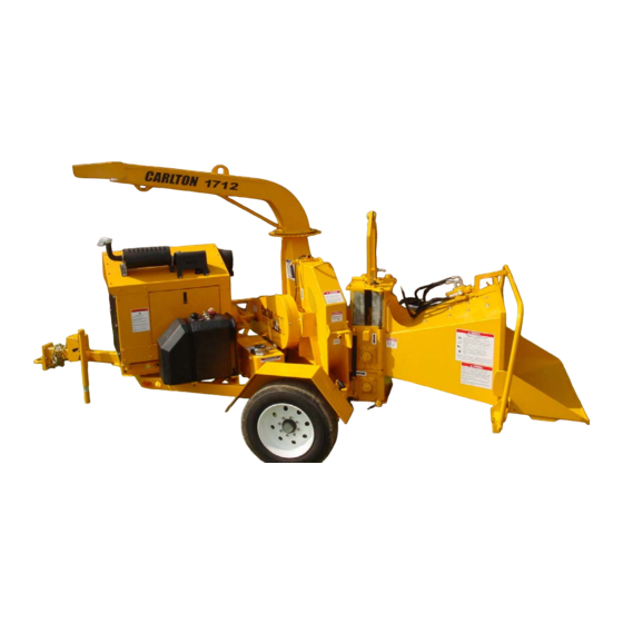
12" Disk Style Brush Chipper
Machine Serial #
Engine Model & Spec #
Engine Serial #
PTO/Clutch Model & Spec #
Clutch Serial #
Purchase Date
Dealer
Carlton
J.P.Carlton Company
Div. D.A.F. Inc.
121 John Dodd Road
Spartanburg, SC 29303
Ph. (864) 578-9335
Fax (864) 578-0210
www.stumpcutters.com
Model 1712
_____________
_____________
_____________
_____________
_____________
_____________
_____________
Advertisement
Table of Contents

Subscribe to Our Youtube Channel
Related Manuals for Carlton 1712


Summary of Contents for Carlton 1712
- Page 1 12” Disk Style Brush Chipper Model 1712 Machine Serial # _____________ Engine Model & Spec # _____________ Engine Serial # _____________ PTO/Clutch Model & Spec # _____________ Clutch Serial # _____________ Purchase Date _____________ Dealer _____________ Carlton J.P.Carlton Company Div. D.A.F. Inc.
- Page 3 DIESEL ENGINE EXHAUST WARNING CALIFORNIA Proposition 65 Warning Diesel engine exhaust and some of its constituents are known to the State of California to cause cancer, birth defects, and other reproduction harm.
- Page 5 12” CHIPPER SAFETY ALERT...
- Page 7 12” CHIPPER SAFETY ALERT...
- Page 9 12” CHIPPER SAFETY ALERT...
- Page 11 12” CHIPPER SAFETY ALERT...
- Page 13 12” CHIPPER SAFETY ALERT...
- Page 15 12” CHIPPER SAFETY ALERT...
- Page 17 12” CHIPPER SAFETY ALERT...
- Page 19 CHIPPER LIMITED WARRANTY J. P. Carlton Co. Inc., hereafter referred to as the “Manufacturer”, warrants each new Carlton Chipper to be free of defects in workmanship and material for a period of one year. This warranty takes effect upon delivery to the original retail purchaser. The manufacturer at its option will replace or repair at a point designated by the manufacturer, any parts which appear to have been defective in material or workmanship.
- Page 21 The manufacturer will provide replacement parts at no cost to the customer for defective parts during the warranty period. Defective parts must be returned to J. P. Carlton Company. It will be the customer’s responsibility to install the replacement parts unless arrangements are made with the selling dealer.
- Page 23 11. _________ Customer has been advised that maintenance and adjustment on the clutch are critical. Customer has been advised that J. P. Carlton Co. does not warrant the clutch and the only warranty that applies is in the clutch manufacturer’s manual. Contact the clutch manufacturer with warranty issues.
-
Page 25: Table Of Contents
12” CHIPPER TABLE OF CONTENTS INTRODUCTION FOREWORD GENERAL INFORMATION MACHINE FEATURES MACHINE SPECIFICATIONS OPERATION SAFETY PRECAUTIONS DAILY CHECKLIST MACHINE CONTROLS TOWING GUIDE MACHINE OPERATION MAINTENANCE MACHINE MAINTENANCE LUBRICATION TROUBLESHOOTING GUIDE SERVICING HYDRAULICS SERVICING PTO/CLUTCH SERVICING CUTTER SYSTEM SERVICING BELTS SERVICING FEED WHEEL MOTOR MACHINE WIRING PARTS DECAL ASSEMBLY... -
Page 27: Foreword
12” CHIPPER FOREWORD Congratulations on your purchase of a new Carlton Professional Chipper! Carlton has built ® ® its reputation on the superior performance and reliability of their stump grinders and you can be assured your new chipper has the same performance and reliability. A machine is not profitable if it’s broken-down and we do our absolute best to help you avoid costly downtime. -
Page 28: General Information
Any reference made to the right, left, front, or rear in relationship to the chipper is illustrated in the following pictures. Please refer to these any time you call your dealer or J. P. Carlton for parts or assistance. -
Page 29: Machine Features
12” CHIPPER MACHINE FEATURES Available Machine Features: • 84 HP diesel turbo • Nev-R-Lube axle • 17” x 12” throat charged engine bearings opening • Digital tachometer • Electric brakes • 48” wide feed intake • Direct drive hydraulic • Front jack stand – opening •... -
Page 30: Machine Specifications
12” CHIPPER MACHINE SPECIFICATIONS General: Hydraulic System: Weight: ----------------- 5360 Pounds Hyd Pump Displcmnt: -.8 Cu in. Length:------------------ 186” Hyd Pump Drv Systm: -Direct Drive off Engine Mount Height: ------------------ 93” Flow: ---------------------8.8 GPM Total Tires: -------------------- 215/75R17.5 Ld Rng H 4805 System Relief:-----------2500 PSI Pd @ 125PSI Oil Tank Capacity: -----9 Gallons... - Page 31 12” CHIPPER SAFETY PRECAUTIONS Before operating the chipper, read this manual, the engine manual, and all the safety decals on the machine. Know all parts of the machine and their functions, especially the shut down procedures in case of emergency. No inexperienced person may operate the chipper. Inexperience may cause injury.
-
Page 32: Operation
(prescription, over the counter, or • Never position, adjust, or move the otherwise). discharge chute while the chipper or • DO NOT modify or change any part the cutter disk are running without written approval from J. P. Carlton Company. - Page 33 12” CHIPPER SAFETY PRECAUTIONS • Always have at least 2 operators at the job site running the chipper. One to load the brush into the feed wheels and the other to maintain the feed control bar in case of an accident. •...
- Page 34 12” CHIPPER SAFETY PRECAUTIONS DO NOT PERFORM MAINTENANCE OF ANY KIND ON THIS MACHINE UNLESS: The engine is turned off The ignition key is removed Positive battery cable is disconnected • YOKE LOCK PIN MUST BE IN The clutch is disengaged POSITION before performing Feed control bar is in neutral maintenance between the feed wheels.
- Page 35 Decals may be purchased from J. • Keep unauthorized persons away from P. Carlton or an authorized dealer. • the chipper operation area. Remove all foreign objects from the chipper...
- Page 36 12” CHIPPER DAILY CHECKLIST It is vital that the owner and operators inspect the chipper each day before operation. This inspection will help identify potential problems that may arise during the workday. The operators must get in the habit of performing this inspection each and every day. By performing this inspection each day, the operators will help minimize downtime and costly repairs.
-
Page 37: Daily Checklist
12” CHIPPER DAILY CHECKLIST • Make sure all personnel are equipped with all applicable safety equipment: − Eye protection − Hearing protection − Hard hat − Short, fitted gloves − Long sleeve shirt − Long pants − Over the ankle work boots with skid resistant soles PERSONAL PROTECTION: All personnel must wear eye and... - Page 38 12” CHIPPER DAILY CHECKLIST • Check tires air pressure. Inflate to tire manufacturers recommended maximum inflation pressure. Inspect tires for wear. Inspect axle caps, replace caps if necessary. Grease axles as suggested by manufacturer. HITCH & HITCH BOLTS • Inspect hitch and hitch bolts. Make sure the tongue extension (if equipped) is properly bolted in place.
- Page 39 12” CHIPPER DAILY CHECKLIST • Inspect knife bolts and nuts for tightness daily. It is very important to check knife bolts and nuts after first hour of operation for new bolts and nuts. It is not uncommon for bolts to loosen slightly during this time.
- Page 40 • Check the feed control bar operation daily for correct operation of Forward, Reverse, and Off positions. Contact your local dealer or J. P. Carlton if operation is not correct. • Inspect the inside of the infeed chute. Check to make sure there are no foreign objects inside the infeed chute.
- Page 41 12” CHIPPER DAILY CHECKLIST • Check and maintain proper engine oil, fuel, radiator coolant, and hydraulic oil levels. RADIATOR CAP ON TOP OF ENGINE Make sure engine is cool before checking. Replenish engine oil, fuel, radiator coolant, and hydraulic oil every morning before starting the machine so there is no danger of fire from hot machine parts or sparks.
- Page 42 12” CHIPPER DAILY CHECKLIST WINCH (OPTIONAL EQUIPMENT) • Inspect winch rope daily. Replace rope if there is any wear, fraying, or cuts. See Machine Controls section for more information. • Check rollers for burrs or sharp edges if rope is damaged in any way. Replace any damaged or worn rollers.
- Page 43 12” CHIPPER MACHINE CONTROLS It is imperative that all operators are familiar with all controls of the chipper. This will make for a much more productive and safer work period. (The actual controls may differ depending on the engine supplied with your chipper.) ENGINE CONTROLS: •...
- Page 44 12” CHIPPER MACHINE CONTROLS • The Auto-Feed Plus ® monitors the engine RPM and controls the feed system based on this information. The Auto-Feed is calibrated when installed in the chipper with a high and low RPM setting for the feed wheels to operate. When the engine RPM is low and the Auto-Feed is on, the hydraulics will not work.
- Page 45 12” CHIPPER MACHINE CONTROLS CLUTCH ENGAGEMENT HANDLE • The clutch is to be engaged and disengaged at low engine speeds only. NEVER ENGAGE OR DISENGAGE THE PTO/CLUTCH AT ENGINE SPEEDS IN EXCESS OF 1200 RPM. Engagement or disengagement of the clutch at elevated engine speeds can cause severe clutch damage.
- Page 46 FLAP WHILE THE CHIPPER IS IN OPERATION OR WHILE THE CHIPPER DISK IS SPINNING! SWIVEL DISCHARGE • Carlton Chippers are equipped with a rotating discharge chute. To rotate the chute to the desired position 1. Pull down and unlock the rotation lock pin 2.
- Page 47 12” CHIPPER MACHINE CONTROLS FEED CONTROL BAR • The feed control bar is located on three sides of the infeed chute; across the top and down each side. • The feed control bar has three distinct positions − In the out position pulled towards the FEED CONTROL BAR rear of the machine the bar is now in the feed position.
- Page 48 LIFT CYLINDER CONTROL VALVE (OPTIONAL EQUIPMENT) • The Carlton chipper may be equipped with a hydraulic yoke lift, which allows LIFT CYLINDER the operator to hydraulically lift the top feed wheel.
- Page 49 12” CHIPPER MACHINE CONTROLS FRONT JACK STAND • Use the front jack stand anytime the FRONT JACK STAND chipper is removed from the tow vehicle. Do not depend on this jack stand to support the machine for stand-alone operation by itself. The tires must be blocked using wheel chocks and the rear jack stand must be used.
- Page 50 12” CHIPPER MACHINE CONTROLS BRAKES & REAR LIGHTS • The chipper’s brakes and lights are connected to the tow vehicle actuator to be activated by the tow vehicle operation. See the Machine Wiring section of this manual for wiring diagram. BREAKAWAY SWITCH •...
-
Page 51: Machine Controls
12” CHIPPER MACHINE CONTROLS WINCH CONTROL VALVE (OPTIONAL EQUIPMENT) • Carlton Chippers may be equipped with a hydraulic winch. The winch is used to pull trees and brush that are too large to carry to the chipper and to assist in lifting the tree into the infeed tray. - Page 52 12” CHIPPER MACHINE CONTROLS • Two hydraulic valves control the winch on this chipper. The hydraulic winch selector valve diverts hydraulic fluid from the feed roller circuit and enables the hydraulic winch circuit. Once the hydraulic winch circuit is enabled the winch control valve controls the hydraulic winch motor.
- Page 53 12” CHIPPER MACHINE CONTROLS • The winch drum rotates counter- clockwise when pulling in loads. If the rope needs to be replaced make sure it is started under the drum. • Winding the rope over the top (clockwise) could cause the rope to rub on the encasement and wear the rope causing fraying and breakage.
-
Page 54: Towing Guide
12” CHIPPER TOWING GUIDE SAFETY: • NEVER ALLOW INEXPERIENCED DRIVERS TO TOW MACHINERY. • ALWAYS MAKE SURE THE TRUCK HITCH AND THE CHIPPER HITCH ARE OF MATCHING STYLE AND SIZE. • ALWAYS MAKE SURE THE TOW VEHICLE AND THE CHIPPER ARE ON LEVEL GROUND BEFORE CONNECTING OR DISCONNECTING THE CHIPPER. - Page 55 12” CHIPPER TOWING GUIDE CONNECT LIGHTS • Connect chipper lights to the tow vehicle. Observe light operation to insure correct electrical connections. • Attach the breakaway switch to the tow vehicle so that it will engage the switch and slow the chipper if the chipper should become uncoupled from the tow vehicle.
- Page 56 12” CHIPPER TOWING GUIDE • The chipper infeed tray must be closed and locked when towing. • First, check the lock pins behind the infeed chute frame to make sure they are in their storage position. • Then close the tray and make sure the spring lock pin is in position and the tray is secured.
-
Page 57: Machine Operation
12” CHIPPER MACHINE OPERATION STARTING – READ THIS MANUAL, THE ENGINE OWNERS’ MANUAL, THE CLUTCH MANUAL, AND ALL SAFETY DECALS ON CHIPPER BEFORE STARTING. SAFETY: • DO NOT ALLOW CHILDREN OR OTHER SPECTATORS TO STAND AND WATCH THE CHIPPER IN OPERATION. ALL OPERATORS MUST WEAR RECOMMENDED PROTECTIVE EQUIPMENT. - Page 58 12” CHIPPER MACHINE OPERATION LOWER THE INFEED TRAY SPRING LOCK PIN • During transportation the infeed tray will be closed and locked using the spring lock pins attached. At the job site, release the lock pins and lower the tray.
- Page 59 12” CHIPPER MACHINE OPERATION AIM DISCHARGE CHUTE • Carlton Chippers are equipped with a rotating discharge chute. To rotate the chute to the desired position 1. Pull down and unlock the rotation lock pin 2. Turn the discharge chute using bar to...
- Page 60 12” CHIPPER MACHINE OPERATION START ENGINE • Key Switch and Gauges are located in clear view on the engine housing • Key switch has 3 positions Off, Run and Start • There is an emergency shutdown bypass switch, which must be held down during starting.
- Page 61 12” CHIPPER MACHINE OPERATION • Start engine at idle speed and allow sufficient time for oil to circulate before proceeding. A two-position throttle is located on the engine cowling. The lower (idle) position is for starting the engine, low speed engine operation during warm up, clutch engagement/disengagement, and engine cool down.
- Page 62 12” CHIPPER MACHINE OPERATION TURN AUTO-FEED PLUS ON • The Auto-Feed Plus® monitors the engine RPM and controls the feed system based on this information. The Auto-Feed® is calibrated when installed in the chipper with a high and low RPM setting for the feed wheels to operate.
- Page 63 SECTIONS IN THIS MANUAL. NEVER ENGAGE OR DISENGAGE ∗ J. P. CARLTON CO. DOES NOT THE PTO/CLUTCH AT ENGINE WARRANT THE CHIPPER CLUTCH. SPEEDS IN EXCESS OF 1200 RPM. READ THE CLUTCH MANUAL FOR Engagement or disengagement of the THE MANUFACTURER’S...
- Page 64 12” CHIPPER MACHINE OPERATION INCREASE THROTTLE • Once the clutch has been fully engaged the engine can be run at full speed. Push the throttle up to increase engine speed. • The engine should always be run at high RPM while material is being chipped. This will help keep the discharge chute from clogging.
- Page 65 12” CHIPPER MACHINE OPERATION • Start feeding smaller diameter trees and brush first and work your way up to the full capacity of the chipper, which is 9” diameter material. Feed pieces long enough for the feed wheels to pick up without endangering yourself by reaching into the infeed chute.
- Page 66 12” CHIPPER MACHINE OPERATION • The Carlton chipper may come equipped LIFT CONTROL (IF EQUIPPED) with a hydraulic yoke lift, which allows the operator to hydraulically lift the top feed wheel. This can be of assistance when feeding large square cut butt ends, which the feed wheels cannot ride up easily.
- Page 67 DO NOT operate the winch if the feed wheels still turn. Contact J. P. Carlton or the local dealer for service. 2. Put the winch in free spool by putting both levers on the winch drum in FREE.
- Page 68 12” CHIPPER MACHINE OPERATION 3. Pull the winch rope to the tree. Always wear leather gloves when handling winch rope. Broken wires will cause injuries. 4. Attach the winch rope to the tree. 5. Secure the winch rope through the loop never on the rope itself.
- Page 69 12” CHIPPER MACHINE OPERATION NEVER ALLOW ANYONE TO OPERATE THE WINCH CONTROL VALVE WHILE AN OPERATOR IS IN THE VICINITY OF THE WINCH ROPE!!! ROPE BURNS OR OTHER INJURIES COULD OCCUR IF THE PERSON BECAME ENTANGLED OR TRIPPED BY THE ROPE. ROPE COULD BREAK OR COME LOOSE AND WHIP AROUND AND CAUSE SEVERE INJURY.
- Page 70 12” CHIPPER MACHINE OPERATION SHUT DOWN PROCEDURES • With engine RPM still high, push the feed control bar to the middle (off) position. Feed wheels should not be turning. • Push the throttle down into the low position so that the engine can slow down (idle) and the clutch can be disengaged.
- Page 71 12” CHIPPER MACHINE OPERATION • The chipper infeed tray must be closed and locked when towing. Make sure the spring lock pins are in position and the tray is secured. First the lock pins behind the infeed chute frame will have to removed and put back into their storage position.
-
Page 72: Machine Maintenance
12” CHIPPER MACHINE MAINTENANCE DO NOT PERFORM MAINTENANCE OF ANY KIND ON THIS MACHINE UNLESS: The engine is turned off The ignition key has been removed The positive battery cable has been disconnected The clutch is disengaged Feed control bar is in neutral All machine parts have come to a complete stop –... - Page 73 Refer to engine manual supplied with your chipper. DIESEL FUEL • Check fuel level daily and replenish as necessary. Carlton chippers are equipped with lockable cap covers.
- Page 74 12” CHIPPER MACHINE MAINTENANCE FUEL FILTER Read the engine manual for special instructions about fuel filter cleaning and FUEL FILTER replacement. Replace the fuel filter every 500 hours of operation or 6 months. Follow the engine owner’s manual on how to remove the filters and to drain the fuel.
- Page 75 • Before starting to chip any wood, always test the feed control bar. Make sure the reverse, stop, and forward feed positions work properly. • Contact Carlton or an authorized dealer immediately if the control bar doesn’t work properly in any of the three positions.
- Page 76 12” CHIPPER MACHINE MAINTENANCE HITCH • Make sure the bolts on the chipper hitch are tightened. If not, tighten to the specified torque for the bolts size. Also, make sure the hitch bolts on the tow vehicle are tightened properly. •...
- Page 77 12” CHIPPER MACHINE MAINTENANCE BREAKAWAY SWITCH • Check to make sure the breakaway switch is working properly. This switch activates the brakes if the chipper ever becomes uncoupled from the tow vehicle. When the switch separates, power is sent to the brakes. Check the wiring for any loose or broken wires.
- Page 78 12” CHIPPER MACHINE MAINTENANCE TIRES AND AXLES • Check tires air pressure daily. Inflate tires as necessary. Keep tire air pressure adjusted based on the temperature and the load. • When towing, make sure the chipper is sitting as close to level as possible to ensure proper tire wear and axle alignment.
-
Page 79: Lubrication
12” CHIPPER LUBRICATION • All of Carlton’s machines are built to be • Below you will find a Lubrication rugged performers. Our design goals are Schedule that will give you the sturdiness, simplicity and reliability. recommended frequency for lubrication. • A regularly scheduled maintenance •... - Page 80 12” CHIPPER LUBRICATION CHIPPER – LEFT SIDE EQUIPPED WITH DEXTER AXLES, EITHER E-Z LUBE® OR NEV-R-LUBE® – SEE DEXTER INFORMATION ENCLOSED IN MANUAL FEED CONTROL BAR GREASE FITTING * GREASE AS NECESSARY EVERY 30-40 HOURS OF OPERATION FEED WHEEL BEARING GREASE FITTING (2 PLACES) * 1 PUMP OF GREASE...
- Page 81 12” CHIPPER LUBRICATION CHIPPER – RIGHT SIDE DISCHARGE SWIVEL PLATE (3 PLACES) GREASE FITTING * GREASE EVERY 3 MONTHS, APPROX. 300 HOURS OF OPERATION EQUIPPED WITH DEXTER AXLES, EITHER E-Z LUBE® OR NEV-R-LUBE® – SEE DEXTER INFORMATION ENCLOSED IN MANUAL CLUTCH ENGAGEMENT HANDLE (CROSS SHAFT) GREASE FITTING...
-
Page 82: Troubleshooting Guide
12” CHIPPER TROUBLESHOOTING GUIDE DO NOT PERFORM ANY INSPECTION OR SERVICE ON THE CHIPPER WITHOUT MAKING SURE: THE CUTTER DISK IS DISENGAGED AND HAS COME TO A COMPLETE STOP; THE CUTTER DISK LOCK PIN IS INSTALLED; THE ENGINE HAS BEEN TURNED OFF, THE IGNITION KEY HAS BEEN REMOVED AND THE BATTERY CABLE HAS BEEN DISCONNECTED;... - Page 83 12” CHIPPER TROUBLESHOOTING GUIDE COMPLAINT CAUSE CORRECTION • • Chipper bearings are Bearings are dry Grease bearings daily using ® overheating Texaco Starplex II grease • • Check the chipper bearing Retighten bolts or setscrews retainer cap for tightness as tight as possible •...
-
Page 84: Servicing Hydraulics
(see Servicing Hydraulics section) • • Hydraulic oil viscosity is Contact JP Carlton or local wrong for atmospheric dealer for recommended oil temperature type for the situation • • Hydraulic pump making loud... - Page 85 PENETRATED. CHECK HOSES AND FITTINGS USING A BOARD OR CARDBOARD; DO NOT USE HAND OR FINGER. ALWAYS WEAR EYE PROTECTION. HYDRAULIC OIL & FILTER • This Carlton chipper has an in-tank hydraulic filter and a level/temp gauge. Check hydraulic oil daily, before and during use. Refill with AW-32 hydraulic oil, same as supplied by the manufacturer.
- Page 86 SERVICE HYDRAULICS • Check hydraulic oil level daily. This Carlton chipper is equipped with a sight glass to check hydraulic oil level. If oil can be seen in glass, oil level is good. Only fill tank 7/8 full to allow for expansion.
- Page 87 12” CHIPPER SERVICE HYDRAULICS HOSES AND FITTINGS • Inspect hoses and fittings for leaks, tightness, wear, or damage. Replace any hoses and fittings that need replacing. • FLUID UNDER PRESSURE CAN PENETRATE THE SKIN AND CAUSE SEVERE INJURY. CHECK HOSES AND FITTINGS USING A BOARD OR CARDBOARD;...
- Page 88 Contact J. P. Carlton or your dealer for more information. • Adjust pressure only if necessary and after testing with a pressure gage.
- Page 89 12” CHIPPER STEIN MFG. PTO/CLUTCH (Depending on engine selection) DO NOT PERFORM MAINTENANCE OF ANY KIND ON THIS MACHINE UNLESS: The engine is turned off The ignition key has been removed The positive battery cable has been disconnected The clutch is disengaged Feed control bar is in neutral All machine parts have come to a complete stop –...
- Page 90 EP (extreme pressure) additive recommended for use in high-speed roller bearings operating at 200°F (93.3°C). ® Carlton uses TEXACO STARPLEX II grease. Listed below are the manufacturer’s suggested guidelines for lubrication: 1. The PTO bearing should be lubricated after each 50 hours of operation.
- Page 91 12” CHIPPER STEIN MFG. PTO/CLUTCH (Depending on engine selection)
- Page 92 12” CHIPPER TWIN DISC PTO/CLUTCH (Depending on engine selection) DO NOT PERFORM MAINTENANCE OF ANY KIND ON THIS MACHINE UNLESS: The engine is turned off The ignition key has been removed The positive battery cable has been disconnected The clutch is disengaged Feed control bar is in neutral All machine parts have come to a complete stop –...
- Page 93 EP (extreme pressure) additive recommended for use in high-speed roller bearings operating at 200°F (93.3°C). ® Carlton uses TEXACO STARPLEX II grease. Listed below are the manufacturer’s suggested guidelines for lubrication: 1. Release Bearing – using a hand-operated...
- Page 94 12” CHIPPER TWIN DISC PTO/CLUTCH (Depending on engine selection) CLUTCH ADJUSTMENT The clutch in this machine does not automatically adjust to compensate for wear of the clutch facing(s) and therefore must be manually adjusted. Maintaining the correct engagement pressure is the responsibility of the owner/operator.
- Page 95 12” CHIPPER TWIN DISC PTO/CLUTCH (Depending on engine selection) CHECK ENGAGEMENT FORCE AT EITHER The preferred method of checking the force END OF THE CROSS-SHAFT required to engage the clutch is using a torque wrench to check the foot-pounds required to engage the clutch. The torque wrench should be used at the cross shaft to measure engagement force.
- Page 96 12” CHIPPER SERVICE CUTTER SYSTEM DO NOT PERFORM MAINTENANCE OF ANY KIND ON THIS MACHINE UNLESS: The engine is turned off The ignition key has been removed The positive battery cable has been disconnected The clutch is disengaged Feed control bar is in neutral All machine parts have come to a complete stop –...
- Page 97 • Knife bolts are of a particular design and nuts are security lock nuts. DO NOT USE ANY OTHER STYLE OF BOLTS AND NUTS. You must purchase these bolts and nuts from Carlton or an authorized dealer.
- Page 98 SHARP EDGE SHARP EDGE failure. • If knives are too narrow to grind, replace with a complete set of new knives. • Knives are hardened steel made to Carton’s specifications. Use only Carlton chipper knives as replacements.
- Page 99 12” CHIPPER SERVICE CUTTER SYSTEM • Reassemble knives in the pocket making sure they seat flat. • Tighten knife bolts and torque the nuts to 90 ft. lbs. • Do not over tighten knife bolts. Torque only to the recommended amount. Knives that are overly tight can crack or bow around the hole.
- Page 100 12” CHIPPER SERVICE CUTTER SYSTEM • Check the clearance between the knives and the anvil. The clearance for the knife to anvil should be between .045” and .065” (1.14 – 1.65 mm). Use a feeler gage that measures within that range.
- Page 101 12” CHIPPER SERVICE CUTTER SYSTEM • Loosen the nuts on the adjustment bolts that are on the far side of the plate (as shown). There are two adjustment bolts. • Using the nuts on the inside of the plate, turn the nuts up toward the machine to move the anvil closer to the knife.
- Page 102 DESCRIPTION 0900114 7.25” x 4” x 1/2” Knife 1/2” Knife Bolt – Special Design – Purchase from 0900125 JP Carlton or Dealer 1/2” Security Lock Nuts – Purchase from JP 0900126 Carlton or Dealer 09001142 6.093” x 4” x 1/2” Knife...
- Page 103 Carton’s specifications. Use only BOLTS & WASHERS Carlton anvils as replacements or damage may occur. Purchase the new anvil from Carlton or an authorized dealer. • To rotate or replace the anvil, remove the anvil bolts and washers. There are three anvil bolts, each with a square washer and a lock washer.
- Page 104 • The anvil is hardened steel made to Carton’s specifications. Use only Carlton anvils as replacements or damage may occur. Purchase the new anvil from Carlton or an authorized dealer. INSERT SETSCREW FROM THIS SIDE – OPPOSITE TO HANDLE USE LOCTITE® RED 262...
- Page 105 12” CHIPPER SERVICE CUTTER SYSTEM REPLACE ANVIL – • Use the handle and put the anvil back PUT THROUGH OPENING & through the slot. Rotate the anvil back ROTATE BACK 90° 90 ° to insert the anvil bolts. • Make sure the hardware is replaced in the correct order.
- Page 106 Check pin for distortion and cracks. • If any problems are discovered, contact Carlton or your local dealer for repair or replacement. THE CUTTER DISK HOOD IS ONE OF THE MOST IMPORTANT PIECES OF SAFETY EQUIPMENT ON THIS CHIPPER.
-
Page 107: Belt Tension
12” CHIPPER SERVICE BELTS DO NOT PERFORM MAINTENANCE OF ANY KIND ON THIS MACHINE UNLESS: The engine is turned off The ignition key has been removed The positive battery cable has been disconnected The clutch is disengaged Feed control bar is in neutral All machine parts have come to a complete stop –... - Page 108 12” CHIPPER SERVICE BELTS ENGINE MUST BE OFF AND IGNITION KEY REMOVED BEFORE CHECKING BELT TENSION. ALL PARTS MUST BE COMPLETELY STOPPED. • Insert a screwdriver or metal bar (a metal ruler would be good) through the slot to check belt tension. •...
- Page 109 12” CHIPPER SERVICE BELTS • Loosen inside jam nuts on adjustment bolts (two places). Turn the outside jam nuts clockwise, moving the engine closer to the right side of the machine and tightening the belts. Make similar adjustments to both bolts to keep sheaves aligned.
- Page 110 12” CHIPPER SERVICE BELTS REPLACING BELTS • Replace belts when they are worn or regularly need adjustment. • Replace belts as a complete set. Old or worn belts will not tension the same as new belts. • Remove belt guard bolts and remove belt guard.
- Page 111 12” CHIPPER SERVICE BELTS • Once belts have been replaced, you will need to loosen the inside jam nuts and tighten the outside jam nuts. • When belts start getting tight, check tension. • Check sheave alignment and make adjustments using engine slide adjuster (jam) nuts.
- Page 112 12” CHIPPER SERVICE BELTS REPLACING SHEAVE OR BUSHING • If it becomes necessary to replace a sheave or bushing, replace only one at a time. Never remove both sheaves at the same time. • This section covers removing and replacing the cutter disk sheave and bushing.
- Page 113 12” CHIPPER SERVICE BELTS • Insert old or new bushing, lining up keyway with the keyway on the shaft. Make sure the key is in position. • Replace bolts in the sheave and tighten until bushing is at the location marked on the shaft earlier.
- Page 114 STARTING CHIPPER AFTER PERFORMING MAINTENANCE. There is a special tool required to separate the motor and coupling once it is off the machine, contact J. P. Carlton or your local dealer to purchase the puller. CHANGE MOTORS ONE AT A TIME. PULLER...
- Page 115 12”CHIPPER SERVICE FEED WHEEL MOTOR WARNING: RELEASE HYDRAULIC PRESSURE BEFORE PERFORMING ANY SERVICE TO HYDRAULIC LINES OR OTHER COMPONENTS. FLUID UNDER PRESSURE CAN PENETRATE THE SKIN AND CAUSE SEVERE INJURY. SEEK IMMEDIATE MEDICAL ATTENTION IF SKIN IS PENETRATED. CHECK HOSES AND FITTINGS USING A BOARD OR CARDBOARD;...
- Page 116 There is a special tool required to separate the motor and coupling once it is off the machine, contact J. P. Carlton or your local dealer to purchase the puller. Attach the separating tool to the coupler as shown and screw the three bolts from the bushing into the tool in the outside holes.
- Page 117 12”CHIPPER SERVICE FEED WHEEL MOTOR Replace with new motor. Clean the threads on the motor, the 1” nut, and the coupling with degreaser before beginning to replace all the parts. Attach the torque arm to the new motor using the 1/2” bolts that were removed. Tighten the bolts and torque to 120 ft.
- Page 118 12”CHIPPER SERVICE FEED WHEEL MOTOR Return the feed wheel motor assembly to the machine and tighten the bolts in the bushing. Tighten each bolt a little at a time to pull the coupling into place as straight as possible. Try not to pull one side on faster than the other or damage may occur to the bushing and the coupling.
-
Page 119: Machine Wiring
WIRING MAY BE DIFFERENT DEPENDING ON ENGINE SUPPLIED WITH THE CHIPPER. IF YOU HAVE A CHIPPER WITH AN ENGINE OTHER THAN KUBOTA, CONTACT J. P. CARLTON, FOR THE WIRING DIAGRAM. SEE THE ENGINE OWNER’S MANUAL FOR THE ENGINE WIRING DIAGRAM. -
Page 120: Decal Assembly
12” CHIPPER DECAL ASSEMBLY CHIPPER – LEFT SIDE ITEM # PART # DESCRIPTION 0700301 DANGER – MOVING PARTS (2 PLACES) 0700302 DANGER – SERVICING NEAR REACH 0700307 DANGER – INJURY/DEATH 0700310 NOTICE – HYDRAULICS/LUBRICATION 0700313 NOTTICE – CHIPPER KNIFE 0700316 WARNING –... - Page 121 12” CHIPPER DECAL ASSEMBLY CHIPPER – RIGHT SIDE ITEM # PART # DESCRIPTION 0700301 DANGER – MOVING PARTS 0700303 DANGER – NEVER RIDE ON, ETC. 0700304 DANGER – AIRBORNE CHIPS 0700306 DANGER – VINE TYPE MATERIAL 0700308 NOTICE – ADJUST PTO/CLUTCH 0700309 NOTICE –...
- Page 122 12” CHIPPER DECAL ASSEMBLY CHIPPER – REAR ITEM # PART # DESCRIPTION 0700318 PUSH - REVERSE 0700305 DANGER – FEED WHEEL SERVICE...
- Page 123 PINTLE, 2 1/2" W/4 HOLE BRKT 0550005 TRAILER JACK- 12" CHIPPER BUINESS LINE CHIPPERS 0550250H #12 TORFLEX AXLE-9" CHIPPER OWNER DOMAIN J.P. CARLTON COMPANY DIV. DAF INC. 0550254 215/75R 17.5 TIRE - 12" CHIPPER SERIAL NUMBERS 1J9PF011591167051 DESCRIPTION ISSUE 21110001...
- Page 124 1 FRAME AND TANKS 21110001 WELDMENT,FRAME BUINESS LINE 21110005 ASSEMBLY,HYDRAULIC TANK CHIPPERS 21110007 WELDMENT,HYDRAULIC TANK STRAP OWNER DOMAIN J.P. CARLTON COMPANY DIV. DAF INC. SERIAL NUMBERS 30A-06 LOCKWASHER, 3/8" USS GR8 1J9PF011591167051 DESCRIPTION ISSUE 31A-06 FLAT WASHER, 3/8 USS GRD 5 INSTALLATION HYDRAULIC/FUEL TANKS Revised 3.15.05...
- Page 125 PART ITEM DESCRIPTION 0200009 Fuel Gauge - 25 Gallon BUINESS LINE CHIPPERS 0200007 TANK,FUEL OWNER DOMAIN J.P. CARLTON COMPANY DIV. DAF INC. 0200008 Fuel Cap - Plastic Tank SERIAL NUMBERS 1J9PF011591167051 DESCRIPTION ISSUE 17510003 WELDMENT,FUEL TANK STRAP ASSY, FUEL TANK Revised 3.15.05...
- Page 126 0300169 STRAINER- TANK MOUNTED LTM-15 BUINESS LINE 0300266 SIGHT GLASS CHIPPERS OWNER DOMAIN 12D-0612 SHCS 3/8 X 1-1/2 NC GR 8 J.P. CARLTON COMPANY DIV. DAF INC. SERIAL NUMBERS 1J9PF011591167051 21110006 WELDMENT,HYDRAULIC TANK DESCRIPTION ISSUE 21210154 BRACKET,VANDADLISM,HYRDRUALIC TANK ASSY,HYDRAULIC TANK Revised 3.15.05...
- Page 127 PLATE,KUBOTA WASHER BUINESS LINE 21220009 PLATE,ENGINE SLIDE CHIPPERS OWNER DOMAIN 30A-10 LOCKWASHER 5/8" USS GR8 ZINC J.P. CARLTON COMPANY DIV. DAF INC. SERIAL NUMBERS 1J9PF011591167051 31B-10ZI FLAT WASHER 5/8 USS NARROW GR 8 Z&Y DESCRIPTION ISSUE 34A-08 FLAT WASHER, NARROW 1/2 SAE GR8 INSTALLATION, KUBOTA ENGINE Revised 3.15.05...
- Page 128 Carlton PROFESSIONAL TREE EQUIPMENT FUCTION GROUP 2 ENGINE/ELECTRICAL BUINESS LINE CHIPPERS PART ITEM DESCRIPTION OWNER DOMAIN J.P. CARLTON COMPANY DIV. DAF INC. 20620011 ASSY,BATTERY BOX SERIAL NUMBERS 1J9PF011591167051 DESCRIPTION ISSUE 21110001 WELDMENT,FRAME BATTERY INSTALLATION Revised 3.15.05 DUE TO CONTINUOUS DESIGN IMPROVEMENTS CONSULT FACTORY PRIOR TO ORDERING 1-800-243-9335.
- Page 129 30-06 LOCK WASHER,3/8" 34A-06 FLAT WASHER, 3/8 SAE GR8 BUINESS LINE CHIPPERS 0350001B 6-WAY CONNECTOR PLUG - 11-605 OWNER DOMAIN J.P. CARLTON COMPANY DIV. DAF INC. 0550050F TEKONSHA BREAKAWAY SWITCH SERIAL NUMBERS 1J9PF011591167051 21810056 PLATE,TAIL LIGHT PLUG COVER DESCRIPTION ISSUE BATTERY INSTALLATION Revised 3.15.05...
- Page 130 DESCRIPTION 2 ENGINE/ELECTRICAL 0150414 RIVET-ALUMINUM W STEEL MANDREL BUINESS LINE CHIPPERS 0350054 MARKER LIGHT- 4" AMBER OVAL OWNER DOMAIN J.P. CARLTON COMPANY DIV. DAF INC. 0350057 REFLECTOR- AMBER 2 3/8" SERIAL NUMBERS 1J9PF011591167051 DESCRIPTION ISSUE 21110001 WELDMENT,FRAME INSTALL MARKER LIGHTS AND REFLECTORS Revised 3.15.05...
- Page 131 1. APPLY GREEN LOCTITE 608 ON BEARING CHIPPERS BOLTS(TORQUE 190 FT/LBS & COLLAR SET OWNER DOMAIN SCREWS (TORQUE 54 FT/LBS). J.P. CARLTON COMPANY DIV. DAF INC. 2. APPLY RED LOCTITE 680 TO SHAFT END SERIAL NUMBERS 1J9PF011591167051 BOLT (TORQUE 340 FT/LBS).
- Page 132 30A-10 LOCKWASHER 5/8" USS GR8 ZINC FUCTION GROUP 3 CUTTER WHEEL/BASE/TRANSITION BUINESS LINE CHIPPERS OWNER DOMAIN J.P. CARLTON COMPANY DIV. DAF INC. SERIAL NUMBERS 1J9PF011591167051 DESCRIPTION ISSUE BASE/TRANSITION/ANVIL Revised 3.15.05 DUE TO CONTINUOUS DESIGN IMPROVEMENTS CONSULT FACTORY PRIOR TO ORDERING 1-800-243-9335.
- Page 133 GR8 Z&Y 3 CUTTER WHEEL/BASE/TRANSITION 20A-08 NUT,HEX,1/2-13 UNC GR8 BUINESS LINE CHIPPERS 21130055 ANVIL,1712 CHIPPER OWNER DOMAIN J.P. CARLTON COMPANY DIV. DAF INC. 30A-08 LOCKWASHER 1/2" SERIAL NUMBERS 1J9PF011591167051 DESCRIPTION ISSUE 31A-08ZI FLAT WASHER 1/2 USS GR 8 Z&Y BASE/TRANSITION/ANVIL Revised 3.15.05...
- Page 134 21130023 CUTTER WHEEL,MACHINED STAGE 3 BUINESS LINE CHIPPERS 21M-10ZI NUT,HEX HIGH NUT,5/8-18 UNF GR 8 Z&Y OWNER DOMAIN J.P. CARLTON COMPANY DIV. DAF INC. SERIAL NUMBERS 70A-0614 KEY ,3/8 SQ. 1-3/4" LONG 1J9PF011591167051 DESCRIPTION ISSUE 70A-1014 KEY,5/8 SQ. 1-3/4" LONG CUTTER WHEEL Revised 3.15.05...
- Page 135 4 FEED SYSTEM 21140011 WELDMENT,FEED TOP BUINESS LINE 21140012 WELDMENT,LIFT CYLINDER MNT CHIPPERS 21140022 ROD,ENGINE SLIDE OWNER DOMAIN J.P. CARLTON COMPANY DIV. DAF INC. SERIAL NUMBERS 21240081 SPRING,LIFT 1J9PF011591167051 DESCRIPTION ISSUE 29A-06 NUT,STOVER LOCK, 3/8-16 UNC GR8 ASSY,FEED SYSTEM Revised 3.15.05...
- Page 136 WASHER,FEED WHEEL COUPLER COVER MOUNT BUINESS LINE CHIPPERS 21240091 COVER,PVC,FEED WHEEL COUPLER OWNER DOMAIN 30A-06 LOCKWASHER, 3/8" USS GR8 J.P. CARLTON COMPANY DIV. DAF INC. SERIAL NUMBERS 1J9PF011591167051 30A-08ZI LOCK WASHER,1/2" USS GR8 Z&Y DESCRIPTION ISSUE 31A-06 FLAT WASHER, 3/8 USS GRD 5 BTM FEED ASSEMBLY Revised 3.15.05...
- Page 137 30A-08ZI LOCK WASHER,1/2" USS GR8 Z&Y BUINESS LINE 31A-06 FLAT WASHER, 3/8 USS GRD 5 CHIPPERS 0150807 BUSHING,HARDENED,1" OWNER DOMAIN J.P. CARLTON COMPANY DIV. DAF INC. 20540025 TUBING,FEED SLIDE SERIAL NUMBERS 1J9PF011591167051 52F-08 SNAP RING,1" DESCRIPTION ISSUE TOP FEED ASSEMBLY Revised 3.15.05...
- Page 138 SOLENOID STOP VALVE 4 FEED SYSTEM 0300121C VALVE,FULLY ADJUSTABLE BUINESS LINE PRESSURE COMENSATED FLOW CHIPPERS CONTROL VAVE OWNER DOMAIN J.P. CARLTON COMPANY DIV. DAF INC. 0300121D PISTON RELIEF VALVE- RPCC-LAN SERIAL NUMBERS 1J9PF011591167051 DESCRIPTION ISSUE 0300173 AUTOFEED BODY 6" CHIPPER...
- Page 139 Carlton PROFESSIONAL TREE EQUIPMENT FUCTION GROUP 5 INFEED SYSTEM BUINESS LINE CHIPPERS OWNER DOMAIN J.P. CARLTON COMPANY DIV. DAF INC. SERIAL NUMBERS 1J9PF011591167051 DESCRIPTION ISSUE INFEED SYSTEM Revised 3.15.05 DUE TO CONTINUOUS DESIGN IMPROVEMENTS CONSULT FACTORY PRIOR TO ORDERING 1-800-243-9335.
- Page 140 5 INFEED SYSTEM 21250098 BUSHING,CONTROL BAR 21250099 SPACER,CONTROL ARM BUINESS LINE CHIPPERS 21250101 FLATBAR,CONTROL LINKAGE OWNER DOMAIN J.P. CARLTON COMPANY DIV. DAF INC. 21550024 TUBING,CONTROL BAR SERIAL NUMBERS 1J9PF011591167051 DESCRIPTION ISSUE JP CARLTON LICENSE PLATE INFEED SYSTEM Revised 3.15.05 DUE TO CONTINUOUS DESIGN IMPROVEMENTS CONSULT FACTORY PRIOR TO ORDERING 1-800-243-9335.
- Page 141 FUCTION GROUP 6 DISCHARGE SYSTEM PART ITEM DESCRIPTION BUINESS LINE CHIPPERS 0150640 KNOB,DISCHARGE ADJUST OWNER DOMAIN J.P. CARLTON COMPANY DIV. DAF INC. 21160002 WELDMENT,DISCHARGE SYSTEM SERIAL NUMBERS 1J9PF011591167051 DESCRIPTION ISSUE 31A-08ZI FLAT WASHER 1/2 USS GR 8 Z&Y DISCHARGE SYSTEM Revised 3.15.05...
- Page 142 1. Panel description and electrical pinout R e v e A u t o - Ref. Description Signal type Pinout INput/OUTput 4-way Delphi connector Back-lit display for visualizing: Heat engine RPM IN (PNP NO, can be set to NPN) max. input frequency: 10KHz Working hours “auto-feed”...
- Page 143 Ground input – monitor power IN (GND) supply 9 4 .5 R P M R e v e rse A u to -F e e d P R O G 5 7 .5 8 9 .5 A Silk-screened front panel in polyester B Front frame in black ABS C Housing in black ABS D Black metal supporting bracket...
- Page 144 2. Operating After turning on the monitor, a 2 seconds test is automatically carried out: all display segments are on; after such a test, working hours are displayed for about 3 seconds, then engine RPMs are displayed and the other display indicators show the working status: Reverse Auto-Feed...
- Page 145 3. Emergency procedure “type 0” This procedure is applied on those machines only where the ACTIVATION of the solenoid valves allows to protect the engine against excessive stress. "BACK" = reverse time 12 V 12 V RPM MAX RPM MIN DISPLAY Auto-Feed Auto-Feed...
- Page 146 4. Emergency procedure “type 1” This procedure is applied on those machines only where the DE-ACTIVATION of the solenoid valves allows to protect the engine against excessive stress. "BACK" = reverse time 12 V 12 V RPM MAX RPM MIN DISPLAY Auto-Feed Auto-Feed...
- Page 147 In case RPMs exceed the RPM maximum value during the reverse interval (back), the activation sequence shall be as shown below: "BACK" = reverse time type 0 12 V 12 V RPM MAX RPM MIN DISPLAY Auto-Feed Auto-Feed Auto-Feed INDICATIONS Reverse Reverse Reverse...
- Page 148 During operation, working hours can always be displayed by switching for a BRIEF INTERVAL key (+) or (-). The display shows now the ref. indicator “b” on page 7 and working hours are displayed for 3 seconds. During this interval the EVS solenoid valve is energized or de-energized by the monitor (according to what programmed in “type”...
- Page 149 7. “User” setting To enter the “user” programming phase, with the monitor ON keep key PROG pressed for at least 2 seconds and until the first parameter "HI" (i.e. RPMs minimum permitted value) is displayed. After an interval of 1 second the current programmed value is displayed (es.
- Page 150 Reverse Auto-Feed Reverse Auto-Feed 1 sec. press both "+" and "-" Reverse Auto-Feed 1 sec. The parameter is changed by using key “+” or “-“; switching key “PROG” allows to go to next parameter “BACK” (i.e. activation time of the reverse solenoid valve, in ms).
- Page 151 How to activate and de-activate the “auto-feed” function The device has a further programming phase, meant for activating and de-activating the “auto-feed” function. This function includes the emergency procedures previously described. NOTE: when the “auto-feed” function is de-activated, the monitor features exclusively revolution counter function and hours counter function;...
- Page 152 -20 / +70 °C Storage temperature range -25 / +85 °C Mechanical vibrations resistance 2 g random Reference standards for the project MC14982 Autofeed Settings for Carlton Chippers Engine Make Engine Model HP Rating High Setting Low Setting Vanguard Big Block V Twin...
- Page 154 Axles equipped with Dexter's E-Z Lube feature can be periodically lubricated without removing the hubs from the axle. This feature consists of axle spindles that have been specially drilled and assembled with grease fittings in their ends. When grease is pumped into the fitting, it is channeled to the inner bearing and then flows back to the outer bearing and eventually back out the grease cap hole.
- Page 155 CAUTION Do not mix Lithium, calcium, sodium or barium complex greases due to possible compatibility problems. When changing from one type of grease to another, it is necessary to insure all the old grease has been removed. If your axles are equipped with oil-lubricated hubs, then your lubrication procedure is to periodically fill the hub with high quality hypoid gear oil to the level indicated on the clear plastic oil cap.
- Page 157 Product Features • No need to pull the hubs to repack the bearings OR replace the seals when checking the brakes. • Pre-set adjustment means installation is easy and human error is virtually eliminated in bearing adjustment. • Pre-lubricated at the bearing factory providing resistance to contamination. •...
- Page 159 CONTACT STEIN MANUFACTURING FOR PARTS...
- Page 160 CONTACT STEIN MANUFACTURING FOR PARTS...
- Page 161 WINCH INFORMATION...
- Page 162 WINCH INFORMATION...
- Page 163 WINCH INFORMATION...
- Page 165 Tow- 7500 Deutz Turbo Diesel 24" 46" 92" arc 31" 1.5" 60" 4,400 Behind Call and ask about Carlton’s line of Chippers or visit our website: www.stumpcutters.com CARLTON—QUALITY PRODUCTS AND EXCEPTIONAL SERVICE Carlton Owner’s Manual 12” Disk Chipper Revised: 09/2009...
Need help?
Do you have a question about the 1712 and is the answer not in the manual?
Questions and answers