
Related Manuals for Extraflame TERMOPELLET TP30


Summary of Contents for Extraflame TERMOPELLET TP30
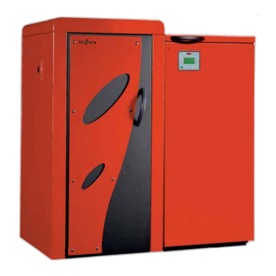
- Page 1 TERMOPELLET TP30 PELLET BOILERS User manual Read the instructions carefully before installation, use and maintenance. The instruction book is an integral part of the product.
- Page 3 Congratulations! You are now the owner of an Extrafl ame boiler The Extrafl ame boiler is a great heating solution developed from the most advanced technology with top quality machining and modern design, aimed at making you enjoy the fantastic sensation that the heat of a fl ame gives, in complete safety.
-
Page 5: Table Of Contents
Index Chapter 1 WARNINGS AND SAFETY DEVICES......................7 Chapter 2 TECHNICAL FEATURES ..........................9 Chapter 3 THE FUEL ..............................12 THE PELLETS ................................... 12 PELLET FEEDING ................................12 PELLET FEED ADJUSTMENT ............................13 Chapter 4 BOILER ADJUSTMENT ..........................14 SELECT THE DESIRED LANGUAGE ..........................14 CURRENT DATE AND TIME SETTING .......................... - Page 6 Chapter 9 BOILER CLEANING ..........................29 DAILY CLEANING ................................... 29 TWO-MONTHLY CLEANING ............................. 30 WEEKLY CLEANING ................................30 Chapter 10 BOILER DISPLAY TABLES ........................31 Chapter 11 WARRANTY .............................. 37...
-
Page 7: Warnings And Safety Devices
Chapter 1 WARNINGS AND SAFETY DEVICES INTRODUCTION The boilers produced by our establishment are built with attention to the individual components in a way to protect both the user and the installer from any accidents. It is therefore recommended that after any intervention on the product, that authorised staff pay particular attention to the electric connections, especially the stripped parts of the wires. - Page 8 Chapter 1 APPROVALS The Extrafl ame boilers have been designed and realised in compliance with the following Directives: UNI EN 303-5 Boilers for central heating. Boilers for solid fuel, with manual and automatic feeding, with a nominal heat output up to 300 kW Compliance with the Low Voltage Directive (73/23 EEC) Compliance with the EMC Directive (Electromagnetic compatibility 89/336 EEC) FOR SAFETY...
-
Page 9: Chapter 2 Technical Features
Chapter 2 TECHNICAL FEATURES Unit of Features Value Measurement Boiler class Introduced global heat output 33.0 Max. useful heat output 29.6 Min. useful heat output Yield > 89 Hourly fuel consumption kg/h 2.1 - 6.9 Flue gas temperature at max. useful heat output °C ~ 180 Flue gas temperature at min. - Page 10 Chapter 2 fi gure 2.1 TECHNICAL FEATURES...
- Page 11 Chapter 2 Pellet feeding Automatic pellet ignition Rotary valve fi re-cut Self-adjusting combustion system and automatic cleaning by means of lambda probe Automatic dispensing of the primary and secondary air fl ow rate Preparation for external storage silo Cleaning device for the external fl ue gas pass Draught for modulating intake with control via encoder of the fl ue gas intake speed Pellet insertion controlled by safety fi re-cut rotary...
-
Page 12: Chapter 3 The Fuel
Chapter 3 THE FUEL THE PELLETS Pellets are realised by subjecting wood shavings i.e. the rejects of pure wood (without paint) sawmill, carpenter products and products from other activities connected to working and transforming wood, to very high pressures. This type of fuel is absolutely ecological as no glues are used to hold it together. In fact, the compactness of the pellets is guaranteed through time by a natural substance that is found in wood: lignite As well as being an ecological fuel, as wood residues are made the most of, the pellet also has technical advantages. -
Page 13: Pellet Feed Adjustment
Chapter 3 PELLET FEED ADJUSTMENT The pellet used must comply with the features described by the Standard: Ö-Norm M 7135 DIN plus 51731 UNI CEN/TS 14961 * Extrafl ame recommends using pellet with 6 mm diameter. Using pellet with features diff erent to those listed above or for the features of the smokes evacuation plant, it is possible that the boiler presents alterations respect to its optimal functioning. -
Page 14: Chapter 4 Boiler Adjustment
Chapter 4 BOILER ADJUSTMENT fi gure 4.1 Before igniting the boiler, it is necessary to set certain parameters by means of the control board. SELECT THE DESIRED LANGUAGE In this section it is possible to select the desired language amongst those available: ITALIANO ENGLISH FRANCAIS... -
Page 15: Current Date And Time Setting
Chapter 4 CURRENT DATE AND TIME SETTING Inside this menu it is possible to set the current day, hours and minutes. Controls procedure: Press key 3 (menu/ok) to access the menu. Press key 3 (menu/ok) to access the “ USER MENU”. Select “... -
Page 16: Trapdoor Activation Time Setting
Chapter 4 hot water storage, puff er, etc.). The ignition of the auxiliary boiler is always delayed by about 20 minutes. Once the biomass boiler functioning is restores, the electronic board will again exclude the auxiliary boiler functioning. By switching off the biomass boiler through key 1, the auxiliary boiler is also switched off . AUX. -
Page 17: Selection Of Functioning Mode
Chapter 4 TRAPDOOR STOP TIME Allows to use buttons 4(-) and 5(+) to set the end time of the active trapdoor phase. To confi rm and continue programming, press button 3 (menu/ok). Press button 2 (set) to go back to the previous parameter. Press button 1 to escape (esc). - Page 18 Chapter 4 C.H. SET allows to set the desired water temperature inside the boiler. The set can be set from a minimum value of 65°C to a maximum of 80°C or the automatic mode can be selected. Setting a value between 65°C and 80°C, the boiler works to reach the desired temperature decreasing the functioning power once nearing the set;...
-
Page 19: Switch-On And Functioning Cycle
Chapter 5 SWITCH-ON AND FUNCTIONING CYCLE Before switching the boiler on the following points must be verifi ed: the combustion chamber must be free and clean. The burners must be completely free and clean. Check hermetic closure of the fi re doors. Check that the power supply cable is connected correctly. - Page 20 Chapter 5 Press button 4(-) once Press button 4(-) twice EXTERN. UPP. PUFFER BOILER/EXCHANGER LOW. PUFFER FLUE T. INT. SPEED LAMBDA PROBE AUX C.HEAT. The value read by the probes can be replaced with other digits: probe excluded SHORT closed contact or short circuit OPEN open contact or probe disconnected To escape the probe reading press any button.
-
Page 21: Chrono Set Menu
Chapter 6 CHRONO SET MENU Controls procedure: Press key 3 (menu/ok) to access the menu. Press key 3 (menu/ok) to access the “ USER MENU”. Select “ CHRONO SET MENU” using buttons 4(-) and 5(+) and press key 3 (menu/ok) to confi rm. The boiler is equipped with a weekly programmer which allows to program 3 time spans within a day to use every day of the week. - Page 22 Chapter 6 DAYS ON 1 Activate the fi rst time span for every day of the week except Saturday and Sunday. To do this use keys 4(-) and 5(+) in the following way: a. key 5(+) scroll the various days b.
- Page 23 Chapter 6 START PROGRAM 3 Set at “OFF” using buttons 4(-) or 5(+), which is found before the time “00:00”, in a way to disable the switch-on of the 3rd time span. To confi rm and continue programming, press button 3 (menu/ok). Press button 2 (set) to go back to the previous parameter.
-
Page 24: Various Boiler Functions
Chapter 7 VARIOUS BOILER FUNCTIONS CHECK-UP This function is carried out every time current is removed and re-applied from the boiler in the “OFF“ status. The check-up checks all the devices constituting the boiler. PUMPS ANTI-FREEZE CYCLE This function avoids the plant water freezing when the boiler is switched off . When the temperature read by some of the boiler probes falls below a determined temperature value the circuit board will activate all of the outputs relative to the pumps/electro-thermal controls. -
Page 25: Chapter 8 Safety Devices
Chapter 8 SAFETY DEVICES FLUE EXHAUST BREAKAGE If the exhaust stops, the electronic board blocks the functioning and sends the boiler in alarm. PELLET FEED MOTOR BREAKAGE If the motor reducer stops, the boiler continues to function until the minimum cooling level is reached. NO IGNITION If a fl ame is not developed during the ignition phase, the appliance automatically attempts ignition again. -
Page 26: Water Boiling Safety Device
Chapter 8 WATER BOILING SAFETY DEVICE In case there is scarce amount of water in the boiler or insuffi cient heat absorption on behalf of the plant due to circulation block, overheating until boiling point of the same water may be caused. A manual re-arm thermostat block the pellet feed motor. -
Page 27: Mounting Of Heat Discharge Valve (Not Supplied)
Chapter 8 The temperature safety sensors must be in place on the machine at a distance no greater than 30 cm from the fl ow connection. Whenever the generators lack a device, those missing can be installed on the thermo product fl ow pipe, within a distance no greater than 1m from the machine. -
Page 28: Automatic Thermostatic Valve
Chapter 8 Cooling circuit upstream pressure must be at least 1.5 bar. 3 bar safety valve Thermometer Manometer Flow Thermal safety valve 95° C Balance Expansion valve vessel Pump Return Load Network fi gure 8.4 AUTOMATIC THERMOSTATIC VALVE The automatic thermostatic mixing valve fi nds applications in solid fuel boilers as it prevents cold water return in the exchanger. -
Page 29: Boiler Cleaning
Chapter 9 BOILER CLEANING Before carrying out any maintenance operation, the boiler must be in “OFF” state and completely cold. At this point, remove power supply to the boiler by directly acting on the rear switch. Never discharge the water from the plant, even partially, in order to avoid mulfunctionings. Periodically check the good functioning and integrity of the pipe and/or smoke exhaust device. -
Page 30: Weekly Cleaning
Chapter 9 WEEKLY CLEANING Every week it is necessary to open the fi re door to remove the ash that has deposited around the burner completely (see fi gure at the side). fi gure 9.3 fi gure 9.4 fi gure 9.5 fi gure 9.6 fi gure 9.7 Every week it is also necessary to open the two... -
Page 31: Boiler Display Tables
Chapter 10 BOILER DISPLAY TABLES LUMINOUS INDICATORS Indicators Description Explanation It is on/off when the fumes exhaust motor is activated/deactivated. It indicates functioning of the fumes It fl ashes when the speed control probe (encoder) is disconnected. expulsion motor. Indicates the consent for pump It is on/off to indicate functioning consent/dissent for the circulation functioning. - Page 32 Chapter 10 In this functioning mode the room thermostats relative to the heating plant (radiators) are always satisfi ed: this means that the circuit board will never enable the pumps (zone 1 and zone 2) relative to the heating Indicates the SUMMER mode. plant except for the safety functions (if the temperature of the water inside the boiler exceeds 87°C, the pump in zone 1 is activated in order to remove the excess heat).
-
Page 33: Display Description
Chapter 10 DISPLAYS Display Description Explanation IGNITION Indicates the pellet ignition phase Phase in which pellet combustion is triggered Indicates the function that prevents pump This function activates every 48 hours by activating all plant PUMP ANTI-LOCK block. pumps/electro-thermal controls. If the C.H. - Page 34 Chapter 10 The boiler must be set in wood/pellet mode. Indicates the preparation phase for boiler START From the status by pressing key 1(esc) this preparation ignition. phase is engaged for boiler ignition. Timer reserved to the Extrafl ame after-sales TIMER XX XXX Timer reserved to the Extrafl ame after-sales dept.
- Page 35 Chapter 10 ALARMS Display Reason Solution In the case of pellet loading conduit overheating the boiler initially CONDUIT CLEANING intervenes by starting the “ ” cycle. If this is not suffi cient, after a period of about 10 minutes the boiler will block, PELLET CONDUIT ALARM showing “...
- Page 36 Chapter 10 Clean the combustion chamber taking care to scrape the walls using the scraper irons. If the pellets used have a greater eating power with respect to that Combustion chamber dirty. declared and used by the company, reduce the fl ow of pellets (see Excessive pellet feed.
- Page 37 Chapter 11 WARRANTY EXTRAFLAME S.p.A. reminds you that the manufacturer is the owner of the rights envisioned by the Legislative Decree dated 2 February 2002, n. 24 and the following warranty does jeopardise these rights. This warranty certifi cate, granted by Extrafl ame S.p.A., with offi ces in Montecchio Precalcino (VI), via dell’Artigianato 10, refers to all stove components supplied by Extrafl ame S.p.A.
- Page 38 In case of replacing particulars, the warranty is not extended. No compensation will be paid for the time the product is ineffi cient. This is the only valid warranty and no one is authorised to issue others in name or on behalf of EXTRAFLAME S.p.A.
- Page 39 Chapter 11 RESPONSIBILITY EXTRAFLAME S.p.A. does not grant any compensation for direct or indirect damages caused or dependant by the product. LAW COURT The Vicenza Law Court is elected as the competent court for any disputes. WARRANTY...
- Page 40 PELLET AND WOOD BOILERS EXTRAFLAME S.p.A. Via Dell’Artigianato, 10 36030 MONTECCHIO PRECALCINO Vicenza - ITALY Tel. 0445/865911 Fax 0445/865912 http://www.lanordica-extraflame.com E-mail: info@extraflame.com Extrafl ame reserves the right to vary the features and data given in this document at any time without forewarning, in order to improve its products.
Need help?
Do you have a question about the TERMOPELLET TP30 and is the answer not in the manual?
Questions and answers