Table of Contents
Advertisement
Quick Links
Advertisement
Table of Contents

Related Manuals for TV One Voyager

Summary of Contents for TV One Voyager
- Page 1 USB 2.0 Fiber Optic KVM Extender System User Guide...
- Page 2 This document applies to Part Numbers: 2350101-01 and 2350201-01. Regulatory Agency Acceptance We hereby certify that the Voyager USB 2.0 Fiber Optic KVM Extender to which this declaration relates conforms to the protection requirements of the EMC Directive as determined by the following standards:...
- Page 3 CE Statement We declare under our sole responsibility that the USB 2.0 Voyager USB, to which this declaration relates, is in conformity with European Standard EN 55022 Class B, EN 61000 and EN 55024. IC Statement This Class B digital apparatus complies with Canadian ICES-003.
-
Page 4: Table Of Contents
Contents Introduction ………………………………………………………………………………………………………………………… Voyager USB 2.0 Fiber Optic KVM Extender Product Contents …………………………………… Requirements ……………………………………………………………………………………………………………………… About the Voyager USB 2.0 Fiber Optic KVM Extender ………………………………………………… CPU Transceiver Description …………………………………………………………………………………………… REMOTE Transceiver Description ……………………………………………………………………………………… Installation guide ………………………………………………………………………………………………………………… Installing the CPU Transceiver ……………………………………………………………………………………………... -
Page 5: Introduction
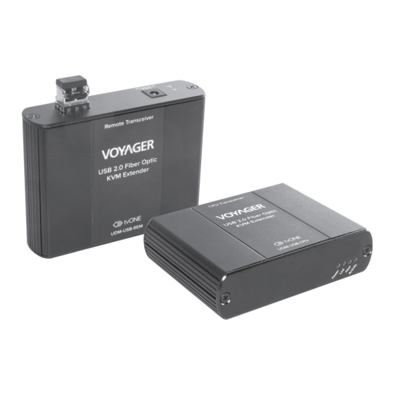
USB peripheral devices. With the Voyager USB 2.0 Fiber Optic KVM extender, USB devices can be located up to 500 meters from the computer. The Voyager USB 2.0 Fiber Optic KVM extender is composed of two individual units: the CPU Transceiver and the REMOTE Transceiver. -
Page 6: Cpu Transceiver Description
Indicates a valid Link is established between the CPU and Link LED (Green) REMOTE transceivers. Indicates that the Voyager USB system is properly enumerated Host LED (Green) on the host computer. LED blinks when in suspend state. Indicates activity when data transmission is active between the CPU and REMOTE Transceivers. -
Page 7: Remote Transceiver Description
Indicates a valid Link is established between the CPU and REMOTE transceivers. Host LED (Green) Indicates that the Voyager USB system is properly enumerated on the host computer. LED blinks when in suspend mode. Activity LED (Amber) Indicates activity when data transmission is active between the CPU and REMOTE Transceivers. -
Page 8: Installation Guide
Determine where you want to locate the USB device(s). If you are using surface cabling, the Voyager USB supports a maximum distance of 500m. If you are using premise cabling, ensure compatible fi ber optic cabling is installed between the two locations, with fi ber optic information outlets located near both the computer and the USB device(s), and the total length including patch cords is no more than 500m over MMF. -
Page 9: Connecting The Cpu Transceiver To The Remote Transceiver
For Mac OS X users, open the System Profiler to confirm that the Voyager USB has installed correctly. In the left hand column under Hardware, select “USB” and inspect the right hand panel. If the Voyager USB has been installed correctly, you should find it listed as a “Hub” under the USB High-Speed Bus/USB Bus. -
Page 10: Connecting A Usb Device
The Voyager USB complies with USB1.1 and USB 2.0 specifications governing the design of USB devices. However, it is not possible to guarantee that all USB devices are compatible with the Voyager USB, as there are a number of different configurations that may impact the operation of USB devices over extended distances. - Page 11 Suspend/Standby mode (see your operating Host LED on operating system may put system’s documentation). CPU/REMOTE the Voyager USB in suspend 2. Attach a USB device to the Voyager USB. Transceivers mode when the computer is are suddenly put into a Suspend/Standby blinking.
- Page 12 USB device • The USB device must have the 1. Install the required USB device driver on the is attached appropriate driver installed computer operating system prior to attaching to REMOTE on the computer operating the USB device to the REMOTE Transceiver. Transceiver system.
-
Page 13: Specifications
USB 2.0: Up to 480 Mbps; USB 1.1: Up to 12 Mbps USB Hub Support Any single chain can include up to 3 USB hubs plus one Voyager USB USB Host Support xHCI (USB 3.0) at USB 2.0 speed, EHCI (USB 2.0) and OHCI/UHCI (USB 1.1) Maximum USB devices 14 USB devices or 3 USB hubs with 11 USB devices. -
Page 14: Contacting Technical Support
Contacting Technical Support If you are experiencing problems not referenced in the Troubleshooting section of this Guide, then please contact tvONE Technical Support and provide them with the following information: • Host computer make and model • Type of Operating System installed (e.g.Windows 8, Mac OS X, etc.) •... -
Page 15: Technical Glossary
Technical Glossary USB Cables USB cables have two distinct connectors. The Type A connector is used to connect the cable from a USB device to the Type A port on a computer or hub. The Type B connector is used to attach the USB cable to a USB device. - Page 16 tvONE NCSA North, Central, and South America 2791 Circleport Drive Erlanger, KY 41018, USA Tel +1 859-282-7303 Fax +1 859-282-8225 Sales: sales@tvone.com Tech Support: tech.usa@tvone.com tvONE EMEA Europe, Middle East, Africa and Asia Pacific Continental Approach, Westwood industrial Estate Margate, Kent, CT9 4JG, UK Tel +44 (0)1843 873311 Fax +44 (0)1843 873312 Sales: sales.europe@tvone.com...
Need help?
Do you have a question about the Voyager and is the answer not in the manual?
Questions and answers