Table of Contents
Advertisement
Copyright
This publication, including all photographs, illustrations and software, is protected
under international copyright laws, with all rights reserved. Neither this manual, nor
any of the material contained herein, may be reproduced without written consent of
the author.
Version 1.0
Disclaimer
The information in this document is subject to change without notice. The manufac-
turer makes no representations or warranties with respect to the contents hereof
and specifically disclaims any implied warranties of merchantability or fitness for
any particular purpose. The manufacturer reserves the right to revise this publica-
tion and to make changes from time to time in the content hereof without obligation
of the manufacturer to notify any person of such revision or changes.
Trademark Recognition
Microsoft, MS-DOS and Windows are registered trademarks of Microsoft Corp.
MMX, Pentium, Pentium-II, Pentium-III, Celeron are registered trademarks of Intel
Corporation.
Other product names used in this manual are the properties of their respective owners
and are acknowledged.
Federal Communications Commission (FCC)
This equipment has been tested and found to comply with the limits for a Class B
digital device, pursuant to Part 15 of the FCC Rules. These limits are designed to
provide reasonable protection against harmful interference in a residential instal-
lation. This equipment generates, uses, and can radiate radio frequency energy and,
if not installed and used in accordance with the instructions, may cause harmful
interference to radio communications. However, there is no guarantee that interfer-
ence will not occur in a particular installation. If this equipment does cause harmful
interference to radio or television reception, which can be determined by turning
the equipment off and on, the user is encouraged to try to correct the interference by
one or more of the following measures:
•
Reorient or relocate the receiving antenna
•
Increase the separation between the equipment and the receiver
•
Connect the equipment onto an outlet on a circuit different from that to
which the receiver is connected
•
Consult the dealer or an experienced radio/TV technician for help
Shielded interconnect cables and a shielded AC power cable must be employed with
this equipment to ensure compliance with the pertinent RF emission limits govern-
ing this device. Changes or modifications not expressly approved by the system's
manufacturer could void the user's authority to operate the equipment.
Q87H3-M6 USER MANUAL
Preface
Advertisement
Table of Contents

Subscribe to Our Youtube Channel
Related Manuals for ECS Q87H3-M6


Summary of Contents for ECS Q87H3-M6
- Page 1 Shielded interconnect cables and a shielded AC power cable must be employed with this equipment to ensure compliance with the pertinent RF emission limits govern- ing this device. Changes or modifications not expressly approved by the system’s manufacturer could void the user’s authority to operate the equipment. Q87H3-M6 USER MANUAL...
-
Page 2: Declaration Of Conformity
Using BIOS ing the BIOS Setup Utility. ® page 47 Describes Intel Matrix Chapter 4 ® Storage Manager RAID Intel Matrix Storage Manager Configurations. RAID Configurations Chapter 5 page 53 Provides basic trouble Trouble Shooting shooting tips. Q87H3-M6 USER MANUAL... -
Page 3: Table Of Contents
Using BIOS About the Setup Utility..............27 The Standard Configuration...........27 Entering the Setup Utility............27 Using BIOS..................28 BIOS Navigation Keys..............29 Main Menu................30 Advanced Menu..............31 Power Menu................39 Authentication Menu..............41 Security Menu.................42 Boot Options Menu..............44 Exit Menu................45 Updating the BIOS..............46 Q87H3-M6 USER MANUAL... - Page 4 Matrix Storage Manager RAID BIOS utility..48 Creating a RAID set................49 Deleting a RAID set................51 Reseting disks to Non-RAID............52 Exiting Setup..................52 Chapter 5 Trouble Shooting Start up problems during assembly..........53 Start up problems after prolong use..........54 Maintenance and care tips..............54 Basic Troubleshooting Flowchart.............55 Q87H3-M6 USER MANUAL...
-
Page 5: Introducing The Motherboard
Chapter 1 Introducing the Motherboard Introduction Thank you for choosing the Q87H3-M6 motherboard. This motherboard is a high per- formance, enhanced function motherboard designed to support the LGA1150 socket for Intel 4 Generation Core Family processors for high-end business or personal desktop markets. -
Page 6: Specifications
1 x USB 3.0 header supports additional two USB 3.0 ports • 2 x Onboard Serial port headers (COM) • 1 x Clear CMOS header with jumper • 1 x Onboard parallel port header (LPT) • 1 x Buzzer • 1 x Case open header Q87H3-M6 USER MANUAL... - Page 7 • Supports Multi-Language • F7 hot key for boot up devices option • Supports PgUp clear CMOS Hotkey(Has PS2KB Model only) • Supports Dual/Triple Display(depends on display output) Form Factor • Micro ATX Size, 244mm x 244mm Q87H3-M6 USER MANUAL...
-
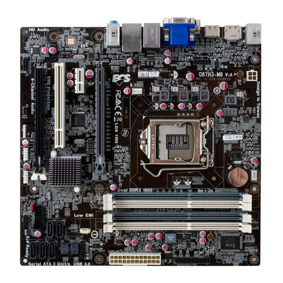
Page 8: Motherboard Components
Motherboard Components Q87H3-M6 USER MANUAL... - Page 9 PCI Express x16 slot (runs at X4 mode) 17. PCI 32-bit add-on card slot 18. PCIE PCI Express x1 slot 19. PCIEX16 PCI Express x16 slot 20. SYS_FAN System cooling fan connector 21. COM1 Onboard serial port header 22. ATX_12V Auxiliary 4-pin power connector Q87H3-M6 USER MANUAL...
-
Page 10: I/O Ports
It can be connected to an external CD/DVD player, Tape player or other audio devices for audio input. 11. Line-out (green) It is used to connect to speakers or headphones. 12. Microphone (pink) It is used to connect to a microphone. Q87H3-M6 USER MANUAL... -
Page 11: Installing The Motherboard
Place the motherboard over the mounting brackets and secure the motherboard onto the mounting brackets with screws. Do not over-tighten the screws as this can stress the motherboard. Q87H3-M6 USER MANUAL... -
Page 12: Checking Jumper Settings
The following illustration shows the location of the motherboard jumpers. Pin 1 is labeled. To avoid the system instability after clearing CMOS, we recommend users to enter the main BIOS setting page to “Load Default Settings” and then “Save and Exit Setup”. Q87H3-M6 USER MANUAL... -
Page 13: Installing Hardware
Lift the tail of the load lever and rotate the load plate to fully open position. Grasp the edge of the package substrate. Make sure pin 1 indicator is on your bottom-left side. Aim at the socket and place the package carefully into the socket by purely vertical motion. Q87H3-M6 USER MANUAL... - Page 14 Spreader). Engage the load lever while pressing down lightly onto the load plate. Secure the load lever with the hook under retention tab. Then the cover will flick automatically. Please save and replace the cover onto the CPU socket if processor is re- moved. Q87H3-M6 USER MANUAL...
-
Page 15: Installing The Cpu Cooler
B. Fasten the cooling fan supporting base onto the CPU socket on the motherboard. And make sure the CPU fan is plugged to the CPU fan connector. C. Connect the CPU cooler power connector to the CPU_FAN connector. Q87H3-M6 USER MANUAL... -
Page 16: Installing Memory Modules
The slot latches are levered upwards and latch on to the edges of the DIMM. The four DDR3 memory sockets (DDR3_1, DDR3_2, DDR3_3 and DDR3_4) are divided into two channels and each channel has two memory sockets as following: Channel A: DDR3_1, DDR3_2 Channel B: DDR3_3, DDR3_4 Q87H3-M6 USER MANUAL... - Page 17 1. For best performance and compatibility, we recommend that users give priority to the white DIMMs (DDR3_2/DDR3_4) when installing DIMMs. 2. We suggest users not to mix memory type. It is recommended to use the same brand and type memory on this motherboard. Q87H3-M6 USER MANUAL...
-
Page 18: Installing Add-On Cards
PCI Express Base Specification revision 2.0. Before installing an add-on card, check the documentation for the card carefully. If the card is not Plug and Play, you may have to manually configure the card before installation. Q87H3-M6 USER MANUAL... - Page 19 Please refer to the following illustrations to install the add-on card: Install the LAN Card in the PCIE X1 slot Install the VGA Card in the PCI slot Install the VGA Card in the PCIE X16 slot Q87H3-M6 USER MANUAL...
-
Page 20: Connecting Optional Devices
2-4-5. Connecting Optional Devices Refer to the following for information on connecting the motherboard’s optional devices: Components Components CASE USB3F F_USB1~2&F_USB3 COM1~2 F_AUDIO SATA3_1~5 Q87H3-M6 USER MANUAL... - Page 21 This detects if the chassis cover has been removed. This function needs a chassis equipped with instrusion detection switch and needs to be enabled in BIOS. 2. LPT: Onboard parallel port header This is a header that can be used to connect to the printer, scanner or other devices. Q87H3-M6 USER MANUAL...
- Page 22 SATA3_1~5 connectors are used to support the Serial ATA 6.0Gb/s device, simpler disk drive cabling and easier PC assembly. It eliminates limitations of the current Parallel ATA interface. But maintains register compatibility and software compat- ibility with Parallel ATA. Q87H3-M6 USER MANUAL...
- Page 23 If you have this kind of case, use auxiliary USB connec- tor to connect the front-mounted ports to the motherboard. Please make sure that the USB cable has the same pin assignment as indi- cated above. A different pin assignment may cause damage or system hang- Q87H3-M6 USER MANUAL...
- Page 24 97 Front Panel, please tick off the option of “ Disabled Front Panel Detect ”. If you use HD Audio Front Panel, please don’ t tick off “Disabled Front Panel Detect ” . * For reference only Q87H3-M6 USER MANUAL...
- Page 25 If you use AC’ 97 Front Panel, please don’ t tick off “Using Front Jack Detect ”. If you use HD Audio Front Panel, please tick off the option of “Using Front Jack Detect ”. * For reference only Q87H3-M6 USER MANUAL...
-
Page 26: Installing A Sata Hard Drive
Attach either cable end to the connector on the motherboard. Attach the other cable end to the SATA hard drive. Attach the SATA power cable to the SATA hard drive and connect the other end to the power supply. * For reference only Q87H3-M6 USER MANUAL... -
Page 27: Connecting Case Components
FAN Power Connector) Connect the CPU cooling fan cable to CPU_FAN. Connect the system cooling fan connector to SYS_FAN. Users please note that the fan connector supports the CPU cooling fan of 1.1A ~ 2.2A (26.4W max) at +12V. Q87H3-M6 USER MANUAL... - Page 28 24-pin power cable Connecting 4-pin power cable The ATX12V4P power connector is used to provide power to the CPU. When installing 4-pin power cable, the latches of power cable and the ATX12V4P match perfectly. 4-pin power cable Q87H3-M6 USER MANUAL...
-
Page 29: Front Panel Header
50 ms to signal the power supply to switch on or off. The time requirement is due to internal de-bounce circuitry. After receiving a power on/off signal, at least two seconds elapses before the power supply recognizes another on/off signal. This concludes Chapter 2. The next chapter covers the BIOS. Q87H3-M6 USER MANUAL... - Page 30 Memo Q87H3-M6 USER MANUAL...
-
Page 31: Using Bios
When you power on the system, BIOS enters the Power-On Self Test (POST) routines. POST is a series of built-in diagnostics performed by the BIOS. After the POST routines are completed, the following message appears: Press DEL to enter SETUP Q87H3-M6 USER MANUAL... - Page 32 The default BIOS setting for this motherboard apply for most conditions with optimum performance. We do not suggest users change the default values in the BIOS setup and take no responsibility to any damage caused by changing the BIOS settings. Q87H3-M6 USER MANUAL...
-
Page 33: Bios Navigation Keys
BIOS items presented in this manual. The BIOS setup screens shown in this chapter are for reference only and may differ from the actual BIOS. Please visit the manufacture’s website for updated manual. Q87H3-M6 USER MANUAL... -
Page 34: Main Menu
The Date and Time items show the current date and time on the computer. If you are running a Windows OS, these items are automatically updated whenever you make changes to the Windows Date and Time Properties utility. Q87H3-M6 USER MANUAL... -
Page 35: Advanced Menu
Magnetic Interface) will reduce if this item is enabled. Processor Multiplier (20) This item shows the information of the processor multiplier. Bootup Num-Lock (On) This item determines if the Num Lock key is active or inactive at system start-up time. Q87H3-M6 USER MANUAL... - Page 36 USB Beep Message (Disabled) This item disables/enables the beep during USB device enumeration. Press <Esc> to return to the Advanced Menu page. Q87H3-M6 USER MANUAL...
-
Page 37: Advanced Chipset Configuration
This item allows you to enable or disable the Intel TXT function. Primary Video (Auto) This item indicates the primary video device setting. Video Memory Size (64MB) This item applies to chipset/motherboards capable of the HyperMemory Support. Q87H3-M6 USER MANUAL... - Page 38 These items will be hidden when Onboard Graphics Controller is set to be disabled or there is no Onboard Graphics Controller. Press <Esc> to return to the Advanced Menu page. Q87H3-M6 USER MANUAL...
-
Page 39: Pci Express Configuration
Version 2.15.1236. Copyright (C) 2002-2013 American Megatrends, Inc. PCI Express 16X/PCIE1/PCI Express X16_S speed (Auto) This item allows users to configure the PCI Express 16X/PCIE1/PCI Express X16_S speed. Press <Esc> to return to the Advanced Menu page. Q87H3-M6 USER MANUAL... -
Page 40: Integrated Peripherals
Onboard LAN Option ROM (Disabled) This item enables or disables the onboard LAN option ROM function. Serial Port1 Address (3F8/IRQ4) Use this item to enable or disable the onboard COM1 serial port, and to assign a port address. Q87H3-M6 USER MANUAL... - Page 41 Parallel Port), ECP (Extended Capabilities Port), EPP (Enhanced Parallel Port), or Bpp (Bi-Directional Parallel Port). Parallel Port IRQ (IRQ7) Use this item to assign IRQ to the parallel port. Press <Esc> to return to the Advanced Menu page. Q87H3-M6 USER MANUAL...
-
Page 42: Pc Health Status
System & CPU temperature, CPU voltage, CPU & system fan speed...etc. • PCH Temperature • Vcore Temperature • CPU Fan Speed • System Fan Speed • Vcore • Vmemory • + 12.0 V • + 5.00V • VCC3 Q87H3-M6 USER MANUAL... -
Page 43: Power Menu
PCI device connected. You must use an ATX power supply in order to use this feature. Use this item to do wake-up action if inserting the PCI device. Q87H3-M6 USER MANUAL... - Page 44 Restore On AC Power Loss (Off) This item defines how the system will act after AC power loss during system operation. When you set Off, it will keep the system in Off state until the power button is pressed. Q87H3-M6 USER MANUAL...
-
Page 45: Authentication Menu
Secure Boot Mode State (Enabled) This item enables or disables the secure boot mode state. Secure Boot (Enabled) This item is used to control the secure boot flow, it is possible only if system runs in User Mode. Q87H3-M6 USER MANUAL... -
Page 46: Security Menu
This item displays the TPM status to be active or not. TPM Owner Status (UnOwned) This item displays the TPM to be owned or not. Removable Device Boot (Enabled) This item enables or disables support the boot from USB mass storage devices. Q87H3-M6 USER MANUAL... - Page 47 This item enables or disables the warning if the case is opened up, and the item below indicates the current status of the case. Chassis Opened (Yes) This item indicates whether the case has been opened. ME Enable (Enabled) Use this item to enable or disable the ME Firmware. Q87H3-M6 USER MANUAL...
-
Page 48: Boot Options Menu
1st/2nd/3rd/4th Boot Device These items show the boot priorities. Hard Disk Drive/ Optical Disk Drive/ Removable Device/ Network Device Priorities These items enable you to specify the sequence of loading the operating system. Press <Enter> to see the submenu. Q87H3-M6 USER MANUAL... -
Page 49: Exit Menu
Load User Default Settings Use this item to restore user defaults. If you have made settings that you do not want to save, use the “Discard Changes and Exit” item and select [OK] to discard any changes you have made. Q87H3-M6 USER MANUAL... -
Page 50: Updating The Bios
When the installation is complete, remove the bootable device from the computer and restart your computer. If your motherboard has a Flash BIOS jumper, reset the jumper to protect the newly installed BIOS from being overwritten. The computer will restart automatically. Q87H3-M6 USER MANUAL... -
Page 51: Intel Matrix Storage Manager Raid Configuration
Create an Intel Matrix Storage Manager driver disk for Windows OS in- stallation. See section “Creating a RAID driver disk” for details. Install the Intel ® Matrix Storage Manager driver after the Windows ® had been installed. Q87H3-M6 USER MANUAL... -
Page 52: Entering Intel ® Matrix Storage Manager Raid Bios Utility
6. Exit DISK/VOLUME INFORMATION RAID Volumes: None defined. Physical Devices: ID Device Model Serial # Size Type/Status (Vol ID) 2 WDC WD2001FASS-0 WD-WMAUR0083571 1.8TB Non-RAID Disk 3 SAMSUNG HD203WI S1UYJ1BZ203313 1.8TB Non-RAID Disk [ ]-Select [ESC]-Exit [ENTER]-Select Menu Q87H3-M6 USER MANUAL... -
Page 53: Creating A Raid Set
Capacity. The default value indicates the maximum capacity using the selected disks. Entering a lower capacity allows you to create a second volume on these disks. [ CREATE VOLUME MENU ] Name: Volume0 RAID Level: RAID0(Stripe) Disks: Select Disks Strip Size: 128KB Capacity: 931.5 Create Volume Q87H3-M6 USER MANUAL... - Page 54 RAID 1 (Mirror) is set to provide the data backup. If you want to set RAID 0, you need to set the 2nd Boot Device item in the BIOS to Intel Volume0. See section “Advanced Setup” for details. Q87H3-M6 USER MANUAL...
-
Page 55: Deleting A Raid Set
Are you sure you want to delete “Volume0”? (Y/N): Deleting a volume will reset the disks to non-RAID. WARNING: ALL DISK DATA WILL BE DELETED. [ ]Select [ESC]-Previous Menu [DEL]-Delete Volume Pressing <Y> deletes all the data in the HDDs. Q87H3-M6 USER MANUAL... -
Page 56: Reseting Disks To Non-Raid
<Enter> to exit the Intel ® Matrix Storage Manager RAID BIOS utility. A dialogue box appears to confirm the action. Press <Y> to confirm; otherwise, press ® <N> to return to the Intel Matrix Storage Manager RAID BIOS menu. Q87H3-M6 USER MANUAL... -
Page 57: Trouble Shooting
1. The CPU may experience overheating so it will shutdown to protect itself. Apply the thermal grease onto the CPU heatsink & ensure the CPU fan is well-connected with the CPU heatsink. Check if the CPU fan is working properly while the system is running. Q87H3-M6 USER MANUAL... -
Page 58: Start Up Problems After Prolong Use
6. If possible, ensure the power cord has an earth ground pin directly from the wall outlet. This will reduce voltage fluctuation that may damage sensitive devices. Q87H3-M6 USER MANUAL... - Page 60 Memo Q87H3-M6 USER MANUAL...
Need help?
Do you have a question about the Q87H3-M6 and is the answer not in the manual?
Questions and answers