Rittal SK 3302 series Assembly And Operating Instructions Manual
Cooling unit sk 3302 series; sk 3302.3 series; sk 3304 series; sk 3305 series; sk 3328 series; sk 3329 series; sk 3332 series; sk 3303 series; sk 3361 series; sk 3366 series; sk 3377 series;
Hide thumbs
Also See for SK 3302 series:
- Assembly and operating instructions manual (52 pages) ,
- Assembly and operating instructions manual (104 pages) ,
- Assembly instructions manual (24 pages)
Table of Contents
Advertisement
Schaltschrank-
Kühlgerät
Cooling unit
Climatiseur
Koelaggregaat
Kylaggregat
Condizionatori per
armadi di comando
Refrigerador
para armarios
SK 3302.xxx
SK 3302.3xx
SK 3303.xxx
SK 3304.xxx
SK 3305.xxx
SK 3328.xxx
SK 3329.xxx
Montage-, Installations- und Bedienungsanleitung
Assembly and operating instructions
Manuel d'installation et de maintenance
Montage- en bedieningshandleiding
Montage- och hanteringsanvisning
Istruzioni di montaggio
Instrucciones de montaje
SK 3332.xxx
SK 3361.xxx
SK 3366.xxx
SK 3377.xxx
R
Advertisement
Table of Contents

Related Manuals for Rittal SK 3302 series


Summary of Contents for Rittal SK 3302 series
- Page 1 Schaltschrank- Kühlgerät Cooling unit Climatiseur Koelaggregaat SK 3302.xxx SK 3332.xxx Kylaggregat SK 3302.3xx SK 3361.xxx Condizionatori per SK 3303.xxx SK 3366.xxx armadi di comando SK 3304.xxx SK 3377.xxx Refrigerador SK 3305.xxx para armarios SK 3328.xxx SK 3329.xxx Montage-, Installations- und Bedienungsanleitung Assembly and operating instructions Manuel d’installation et de maintenance Montage- en bedieningshandleiding...
-
Page 3: Table Of Contents
4.7.2 Fitting the cooling unit....21 4.7.3 Setting the filter mat monitor (only with Comfort controller) ... . 21 Rittal cooling unit assembly instructions... -
Page 4: Notes On Documentation
(refer to enclosed with the unit in the form of a PDF file the accessories in the Rittal Catalogue). This raises (Adobe Acrobat) on CD-ROM. the door slightly and balances out the weight of the... -
Page 5: Device Description
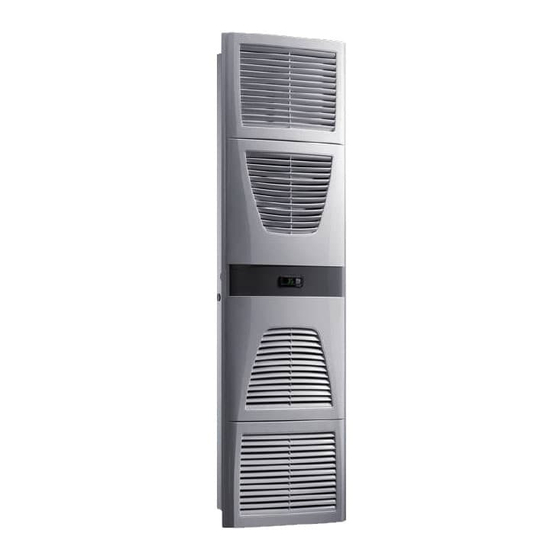
Rear half of the enclosure Louvred grille for air outlet 3.1.2 Controller Controller Rittal enclosure cooling units are fitted with a control- Infill panel ler for setting the functions of the cooling unit. Louvred grille for air inlet Depending on the design, this is either a Basic con-... -
Page 6: Safety Equipment
(see “4.4 Connect- ing the condensate drain”, page 11). External con- densate evaporators are available as accessories for these unit types (refer also to the accessories in the Rittal Catalogue). Rittal cooling unit assembly instructions... -
Page 7: Additional Interface X3
3.2 Proper usage – The site must be free from excessive contamina- tion and moisture. Rittal enclosure cooling units were developed and – The ambient temperature must not exceed 55°C. designed in accordance with the state of the art and the recognized rules governing technical safety. -
Page 8: Layout Of The Electronic Components In The Enclosure
To this end, cut the side panel or door of the enclo- Air diversion components are available as acces- sure as per the drilling template included with the sories – please refer to the Rittal Catalogue under supply, and drill the relevant holes. “System climate control”. -
Page 9: Cutting Out The Enclosure
• Secure the unit using the washers and nuts cable gland. supplied. Fig. 7: Secure the cooling unit (all models except SK 3302.1xx) Fig. 10: Remove the louvred grille & disconnect the display Rittal cooling unit assembly instructions... - Page 10 Fig. 12: Attach the sealing tape • Push the rear enclosure half into the mounting cut-out and secure it with the four spacer bolts. • Push the display cable through the cable gland of the front enclosure half. Rittal cooling unit assembly instructions...
-
Page 11: Full Internal Mounting Of The Cooling Unit
– must not have a reduced cross-section if extended. The condensate hose is available as an accessory (refer to Accessories in the Rittal Catalogue). Fig. 16: Attach the sealing tape • Loosen the four nuts and washers from the front enclosure half. -
Page 12: Notes On Electrical Installation
(e.g. BUS) experience interference, a line reactor or starting-current limiting device should be connected upstream of the cooling unit to restrict the startup current of the cooling unit. Rittal cooling unit assembly instructions... -
Page 13: Potential Equalisation
4 Assembly and connection 4.5.6 Potential equalisation Note: Rittal recommends connecting a conductor with a The electrical signals at the X2 interface are nominal cross-section of at least 6 mm to the poten- extra-low voltages (not safety extra-low tial equalisation connection point in wall-mounted voltages to EN 60 335-1). -
Page 14: Installing The Power Supply
Master/slave connection Sub-D, 9-pole Serial interface cable Serial interface Sub-D, 9-pole Master/slave bus cable (Model No. SK 3124.100) Sub-D connector, 9-pole RTT Rittal TopTherm cooling units Bu. Sub-D jack, 9-pole Supply connection/door limit switch/alarms Adr. Address Adr.: 06 Adr.: 11 Adr.: 12... - Page 15 1 2 3 NTC I red Serial NTC E blue Power NTC C white NTC A yellow Level green Term 1 2 3 1 2 3 1 2 3 Fig. 22: Electrical wiring plan no. 2 Rittal cooling unit assembly instructions...
- Page 16 1 2 3 Fig. 23: Electrical wiring plan no. 3 SK 3304.100/.200 Mains 1 2 3 NTC I red NTC E blue Power Term 1 2 3 1 2 3 Fig. 24: Electrical wiring plan no. 4 Rittal cooling unit assembly instructions...
- Page 17 SK 3304.240, SK 3305.240, SK 3328.240, SK 3329.240, SK 3366.140/.240, SK 3377.140/.240 Mains F11 F12 NTC I red NTC E blue Power Term 1 2 3 4 1 2 3 4 1 2 3 2 3 4 1 2 Fig. 26: Electrical wiring plan no. 6 Rittal cooling unit assembly instructions...
- Page 18 1 2 3 NTC I red Serial NTC E blue Power NTC C white NTC A yellow Level green Term 1 2 3 1 2 3 1 2 3 Fig. 28: Electrical wiring plan no. 8 Rittal cooling unit assembly instructions...
- Page 19 SK 3332.140/.240 Mains F11 F12 NTC I red Term NTC E blue Power 1 2 3 4 1 2 3 4 2 3 4 1 2 3 1 Fig. 30: Electrical wiring plan no. 10 Rittal cooling unit assembly instructions...
- Page 20 LED operational green LED alarm red Compressor Condenser fan Evaporator fan Potentiometer for setting the temperature Door limit switch (without door limit switch: terminal 1, 2 open) Transformer (optional) Main connection clamping strip Master/slave connection Optional interface Rittal cooling unit assembly instructions...
-
Page 21: Finalising Assembly
You can now make your individual settings on the unit e.g. set the temperature or (with Comfort control- ler only) assign the network identifier etc. (refer to the chapter on “Operation”). Fig. 33: Attach the louvred grille and connect the display Rittal cooling unit assembly instructions... -
Page 22: Operation
The built-in Temperature setting basic regulator ensures automatic normal shut-down LED green (“line”) operation of the cooling unit by the value of the fixed LED red (“alarm”) preset switching difference of 5 K. Reset button Rittal cooling unit assembly instructions... -
Page 23: Operating And Error Display
4 – 5 closed). This is the normal operating state of the cooling unit. As soon as an error mes- sage occurs or the power supply is interrupted, the relay drops out. Fig. 35: Releasing the trim panel of the Basic controller Rittal cooling unit assembly instructions... -
Page 24: Setting The Temperature
7-segment display – Using an interface card (Model No. SK 3124.100), the unit may be incorporated into superordinate remote monitoring systems such as the Rittal Computer Multi Control CMC. Rittal cooling unit assembly instructions... -
Page 25: Launching Test Mode
In order to save energy, do not set the temperature any lower than is actually necessary. Note on useful cooling output: Interactive performance diagrams for calculating the useful cooling output may be found at www.rittal.com. Rittal cooling unit assembly instructions... -
Page 26: Variable Parameters
5 K, then error message A2 (internal enclosure temperature too high) appears on the display terminal. If necessary, the differ- ential may be altered here within the range from 3 – 15 K. Tab. 4: Variable parameters Rittal cooling unit assembly instructions... -
Page 27: Programming Overview
6 Operation 6.2.5 Programming overview Fig. 37: Programming overview Rittal cooling unit assembly instructions... -
Page 28: Defining System Messages For Evaluation
System message is not sent to the system message relay, but merely appears in the – Terminal 5: NO (normally opened) display System messages is evaluated by relay 1 System messages is evaluated by relay 2 Rittal cooling unit assembly instructions... -
Page 29: Setting The Master/Slave Identifier
14: Slave cooling unit no. 4 15: Slave cooling unit no. 5 16: Slave cooling unit no. 6 17: Slave cooling unit no. 7 18: Slave cooling unit no. 8 19: Slave cooling unit no. 9 Rittal cooling unit assembly instructions... - Page 30 Display message Connection problem between display Reset: Switch power supply off, then switch on and controller board again after approx. 2 sec. Cable defective; connection loose Exchange the boards Tab. 6: Troubleshooting with the Comfort controller Rittal cooling unit assembly instructions...
-
Page 31: Resetting The Comfort Controller
Depending on the level of contamination in the am- bient air, the maintenance interval may be reduced to suit the air pollution intensity. Caution! Risk of fire! Never use flammable liquids for cleaning. Fig. 40: Remove the upper louvred grille Rittal cooling unit assembly instructions... - Page 32 7 Inspection and servicing Fig. 41: Remove the lower louvred grille Fig. 43: Disconnect the connector from the display (1) Fig. 44: Disconnect the connector from the display (2) Fig. 42: Remove the infill panel Rittal cooling unit assembly instructions...
- Page 33 Fig. 49: Remove the cover (loosen the four screws) Fig. 46: Remove the external circuit fan Fig. 50: Push back the display cable (loosen the four screws) Fig. 47: Remove the fan Fig. 51: Push the display cable through the cable gland Rittal cooling unit assembly instructions...
- Page 34 Fig. 52: Remove the cover (1) Fig. 55: Loosen the earthing cable between the cover and the chassis (2) Fig. 53: Remove the cover (2) Fig. 56: Clean out the heat exchanger coil and compressor chamber using compressed air (1) Rittal cooling unit assembly instructions...
-
Page 35: Compressed Air Cleaning Sk 3328
Fig. 59: Remove the upper louvred grille (1) chamber using compressed air (2) 7.1.2 Compressed air cleaning SK 3328.xxx, SK 3329.xxx, SK 3332.xxx Fig. 58: Disconnect the power cord Fig. 60: Remove the upper louvred grille (2) Rittal cooling unit assembly instructions... - Page 36 7 Inspection and servicing Fig. 61: Remove the upper louvred grille (3) Fig. 63: Remove the lower louvred grille (2) Fig. 62: Remove the lower louvred grille (1) Fig. 64: Remove the infill panel Rittal cooling unit assembly instructions...
- Page 37 Fig. 67: Push back the display cable Fig. 71: Disconnect the fan connectors (2) and press it through the cable gland (2) Fig. 68: Loosen the four screws of the external circuit fan Fig. 72: Disconnect the fan connectors (3) Rittal cooling unit assembly instructions...
- Page 38 Fig. 73: Disconnect the fan earthing cable (1) Fig. 74: Disconnect the fan earthing cable (2) Fig. 76: Remove the cover Fig. 75: Loosen the four screws of the cover Fig. 77: Disconnect the earthing cable (1) Rittal cooling unit assembly instructions...
- Page 39 (2) Fig. 79: Clean out the heat exchanger coil and compressor Fig. 81: Clean out the heat exchanger coil and compressor chamber using compressed air (1) chamber using compressed air (3) Rittal cooling unit assembly instructions...
-
Page 40: Storage And Disposal
During storage, the cooling unit must stand upright. The closed cooling circuit contains refrigerant and oil which must be properly disposed of for the sake of the environment. Disposal can be carried out at the Rittal plant. Please contact us for advice. Rittal cooling unit assembly instructions... -
Page 41: Technical Specifications
IP 54 – External circuit – IP 34 Dimensions (W x H x D) 280 x 550 x 140 525 x 340 x 153 280 x 550 x 200 400 x 950 x 260 Weight Rittal cooling unit assembly instructions... - Page 42 Protection category to EN 60 529/10.91 – Internal circuit – IP 54 – External circuit – IP 34 Dimensions (W x H x D) 400 x 950 x 260 400 x 1580 x 290 Weight Rittal cooling unit assembly instructions...
- Page 43 Protection category to EN 60 529/10.91 – Internal circuit – IP 54 – External circuit – IP 34 Dimensions (W x H x D) 450 x 1590 x 195 450 x 1590 x 165 Weight Rittal cooling unit assembly instructions...
-
Page 44: List Of Spare Parts
10 List of spare parts 10 List of spare parts SK 3302.xxx Fig. 83: Spare parts for SK 3302.xxx SK 3302.3xx Spare parts for SK 3302.3xx Rittal cooling unit assembly instructions... - Page 45 10 List of spare parts SK 3303.xxx SK 3361.xxx Spare parts for SK 3303.xxx, SK 3361.xxx SK 3304.xxx SK 3305.xxx Spare parts for SK 3304.xxx, SK 3305.xxx Rittal cooling unit assembly instructions...
- Page 46 10 List of spare parts SK 3328.xxx SK 3329.xxx Spare parts for SK 3328.xxx, SK 3329.xxx SK 3332.xxx Fig. 84: Spare parts for SK 3332.xxx Rittal cooling unit assembly instructions...
- Page 47 This information may be found Louvred grille 1 on the rating plate. Louvred grille 2 Infill panel Controller Temperature sensor Enclosure tray Transformer Evaporator coil 100 Condenser 101 Condensate evaporator 102 Miniature fuse, condensate evaporator Rittal cooling unit assembly instructions...
-
Page 48: Appendix: Cut-Out And Hole Sizes
Ø 9.5 (8x) Fig. 89: SK 3304.xxx/SK 3305.xxx external mounting Fig. 86: SK 3302.3xx external mounting Ø 8 (4x) Ø 13 (10x) Fig. 87: SK 3303.xxx/SK 3361.xxx external mounting Fig. 90: SK 3328.xxx/SK 3329.xxx external mounting Rittal cooling unit assembly instructions... -
Page 49: Dimensions For Partial Internal Mounting
18 x 45° (230) Fig. 92: SK 3303.xxx partial internal mounting Ø 13 (4x) Fig. 95: SK 3332.xxx partial internal mounting 25 x 45 Ø 9.5 (4x) Fig. 93: SK 3304.xxx/SK 3305.xxx partial internal mounting Rittal cooling unit assembly instructions... -
Page 50: Dimensions For Full Internal Mounting
R95 (2x) Ø 19 (2x) Fig. 100: SK 3328.xxx/SK 3329.xxx full internal mounting Ø 8 (4x) 18 x 45° (230) Fig. 98: SK 3303.xxx/SK 3361.xxx full internal mounting Fig. 101: SK 3366.xxx/SK 3377.xxx full internal mounting Rittal cooling unit assembly instructions... - Page 51 Soluzioni per IT Soluciones TI Communication Systems Communication Systems Armoires outdoor Outdoor-behuizingen Communication Systems Soluzioni outdoor Sistemas de comunicación Rittal GmbH & Co. KG · Postfach 1662 · D-35726 Herborn Telephone: +49(0)2772 505-0 · Telefax: +49(0)2772 505-2319 · eMail: info@rittal.de ·...
Need help?
Do you have a question about the SK 3302 series and is the answer not in the manual?
Questions and answers