
Subscribe to Our Youtube Channel
Related Manuals for Medeli FD900

Summary of Contents for Medeli FD900
- Page 1 DIGITAL DELAY & REVERB EFFECTS PEDAL Owner's Manual aw_FD900_Manual_G07_101105 2010 16:54:16...
- Page 2 INFORMATION FOR YOUR SAFETY! PRECAUTIONS PLEASE READ CAREFULLY BEFORE PROCEEDING. Please keep this manual in a safe place for future reference. Power Supply Interference with other electrical devices Please connect the designated AC adaptor to an AC Radios and televisions placed nearby may experience outlet of the correct voltage.
-
Page 3: Table Of Contents
Contents Panel Description .......... 05. HALL III REVERB Front Panel ....................05. HALL III REVERB ........06. CHURCH REVERB Setup ......... 07. SPRING REVERB Battery Replacement Diagram ............... 08. PLATE REVERB ........09. REVERSE REVERB Connection ...................... 10. -
Page 4: Panel Description
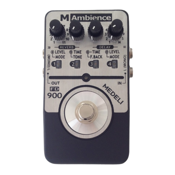
Panel Description Front Panel aw_FD900_Manual_G07_101105 2010 16:54:17... - Page 5 Panel Description 8. DELAY LEVEL Knob: 1. REVERB MODE Knob: Control the effect level of delay. Select one kind of reverb among the 11 reverb modes. 9. PATCH MEMORY Buttons: Press and hold anyone of the PATCH 2. REVERB LEVEL Knob: MEMORY buttons to store your favorite tones.
- Page 6 Panel Description 13. INPUT Jack: IN-L(MONO): Connect your guitar to this jack. Connect a guitar cable to this jack for power supply when using a battery. IN-R: Connect another guitar to this jack. Notice: You can also connect a stereo signal to this 2 combinational input jack, such as keyboard, synth, electronic drum, audio player, and so on.
-
Page 7: Setup
Setup Battery Replacement Diagram Warning: 1. A 9V battery (optional) must be installed before you plug the mono audio cable into the input jack. 2. While the power supply is low, the LED will extinguish. Please replace the battery accordingly. 3. -
Page 8: Connection
Connection Connection AC Adaptor 1. Connect the optional power supply to the power jack or insert a 9V battery (optional) into the battery compartment on the bottom. OUT DC 9V OUT L (MONO) 2. Connect your guitar to input jack and an amplifier to output jack of the Pedal. - Page 9 Connection AC Adaptor OUT DC 9V Amplifier I OUT R OUT L Amplifier II aw_FD900_Manual_G07_101105 2010 16:54:18...
-
Page 10: Effects Introduction
Effects Introduction This is a digital delay and reverb effects pedal, contains 10 excellent delay effects and 11 excellent reverb effects. It also includes the storage function, allows you to store and recall up to 4 patch memories. Effects List DELAY MODE REVERB MODE 10~1000ms STEREO DELAY... -
Page 11: Delay
Effects Introduction Delay 01. 10~1000ms STEREO DELAY 02. 1000~3000ms STEREO DELAY L-INPUT DELAY To REVERB L-INPUT Stereo delay effects. Requires stereo inputs. Send the left input signal to reverb left input, the DELAY To REVERB R-INPUT R-INPUT right input signal to reverb right input through delay process. -
Page 12: 1000Ms Modulated Delay
Effects Introduction 08. 10~1000ms MODULATED DELAY L-INPUT DELAY To REVERB L-INPUT Modulated delay effects, add some chorus effects. Send the left input signal to reverb input To REVERB R-INPUT through delay process. 09. 100~3000ms REVERSE DELAY L-INPUT DELAY To REVERB L-INPUT Reverse delay effects, the repeating sound are played backwards. - Page 13 Effects Introduction After first recording, M1~M4 will be lighted one by one to show the beat. The light will keep on showing till the memory is cleared. To stop the loop, there are two methods: 1> Turn DELAY MODE to other positions. 2>...
-
Page 14: Reverb
Effects Introduction 08. PLATE REVERB Reverb Simulate a type of reverb sound caused by 01. ROOM I REVERB a metal plate, it provides a metallic reverb sound with extended high-band ending. 02. ROOM II REVERB Simulate the reverb sound of room with 09. -
Page 15: Store And Recall Patches
Store and Recall Patches Storing Your Favorite Tones You can store your favorite tones into one of the 4 patches when the pedal DELAY MODE knob is turned to a position between DELAY MODE 1~9 and the ON/OFF LED indicator is on at the same time. Notice:... -
Page 16: Recalling The Saved Memories
Store and Recall Patches Press and hold the 2nd button for another 2 seconds to enter the storage function; all LED indicators will flash from 1 to 4 in a fast speed. You can then release the button. The LED indicator of this button will be lighted for the final one second, then the whole action will stop;... -
Page 17: Advanced Use
Advanced Use FOOT SWITCH Control Mode MODE FUNCTION When DELAY MODE knob points to the M position, MODE 1 FOOT SWITCH for the bypass function as the FOOT SWITCH will provide two function modes. usual. Before making connection or powers on the padel, MODE 2 FOOT SWITCH swaps between the patch turn the DELAY MODE knob to the M position, then... -
Page 18: Effect Trails Mode
Advanced Use Effect Trails Mode MODE FUNCTION There are two function modes to enter BYPASS. MODE 1 When pressing FOOT SWITCH to enter Users can choose whether keep the effect sound BYPASS, the effect sound will be stopped. persisting when entering BYPASS. MODE 2 When pressing FOOT SWITCH to enter The default BYPASS entry mode is MODE 1,to... -
Page 19: Bypass Pan Mode
Advanced Use Bypass Pan Mode MODE FUNCTION There are two function modes to select pan setting MODE 1 STEREO DELAY: L-OUTPUT = L-INPUT, at BYPASS state. When BYPASS, the default R-OUTPUT=R-INPUT BYPASS pan mode (MODE 1) of the pedal is setting Rest Delay Modes: like these: L-OUTPUT= R-OUTPUT=L-INPUT... -
Page 20: Tap Tempo Delay
Advanced Use battery, press and hold the FOOT SWITCH firmly, Notice: then plug INPUT and keep holding the FOOT DELAY TIME knob is inactivated when using SWITCH until the ON/OFF LED indicator flashes tap tempo delay. When entering tap tempo three times). - Page 21 Troubleshooting Can't power on [On/Off LED doesn't light Are you in TAP TEMPO function (On/Off LED flashes)? normally] When in TAP TEMPO function, the On/Off Check the connection of power. LED flashes to indicate tempo (Read details Make sure the power is connected correctly. on Page.17~18, “Tap Tempo Delay”) Check the adaptor, is the type of adaptor right (DC9V/300mA/center negative type)?
-
Page 22: Troubleshooting
Troubleshooting DELAY LEVEL knob to a appropriate value . Check the IN/OUT jack, when in STEREO DELAY MODE, OUT-L jack only output the IN- L jack's signal, OUT-R jack only output the IN- Distorted sound Check the battery, is it low? R jack's signal, do you make a corresponding Replace with a new one. -
Page 23: Specifications
Specifications Output impedance: No. of Delay Types: 100 Ohms No. of Reverb Types: Power Requirements: AC adaptor DC9V/300mA/center negative type or 6LR61 9V battery No. of Patch Memories: Dimensions: 126.5(L) x 79.5(W) x 64.5(H) mm Guitar Input: Weight : a pair of 1/4" monaural jack 355g (without battery) Input impedance: 1 M Ohms... -
Page 24: Appendices
Appendices Setting Samples 3. PAN MOD. DELAY DELAY Warning: When using DELAY alone, turn the REVERB LEVEL knob to minimum, other parameters of REVERB will not interfere with the DELAY effects. 1. SHORT STEREO DELAY 4. SHORT MONO DELAY 5. MIDDLE MONO DELAY 2. - Page 25 Appendices 6. LONG MONO DELAY 9. REVERSE DELAY 7. ANALOG DELAY 8. MODULATED DELAY aw_FD900_Manual_G07_101105 2010 16:54:19...
- Page 26 Appendices : 3. SMALL HALL REVERB REVERB Warning: When using REVERB alone, turn the DELAY LEVEL knob to minimum, DELAY MODE should not point to “S” or “M”, then the DELAY TIME knob and DELAY F.BACK knob will not interfere with the REVERB effects. 1.
- Page 27 Appendices 6. CHURCH REVERB 9. REVERSE REVERB 7. SPRING REVERB 10. GATE REVERB 11. MODULATE REVERB 8. PLATE REVERB aw_FD900_Manual_G07_101105 2010 16:54:20...
- Page 28 Appendices DELAY + REVERB 3. MONO DELAY + CHURCH REVERB 1. MONO DELAY + ROOM REVERB 2. MONO DELAY + HALL REVERB 4. MONO DELAY + MODULATE REVERB aw_FD900_Manual_G07_101105 2010 16:54:20...
- Page 29 Appendices 5. PAN MOD. DELAY + SPRING REVERB 7. MODULATED DELAY HALL REVERB 6. ANALOG DELAY + PLATE REVERB 8. MODULATED DELAY REVERSE REVERB aw_FD900_Manual_G07_101105 2010 16:54:20...
- Page 30 Appendices 9. REVERSE DELAY + SPRING REVERB 11. User Setting 10. REVERSE DELAY + GATE REVERB 12. User Setting aw_FD900_Manual_G07_101105 2010 16:54:20...
- Page 31 Appendices 13. User Setting 15. User Setting 14. User Setting 16. User Setting aw_FD900_Manual_G07_101105 2010 16:54:20...
- Page 32 FD900_G07 aw_FD900_Manual_G07_101105 2010 16:54:20...
Need help?
Do you have a question about the FD900 and is the answer not in the manual?
Questions and answers