Vertex Standard VXA-710 Spirit Operating Manual
Air band transceiver
Hide thumbs
Also See for VXA-710 Spirit:
- Operating manual (64 pages) ,
- Specifications (2 pages) ,
- Service manual (40 pages)
Table of Contents
Advertisement
Quick Links
Download this manual
See also:
Service Manual
Advertisement
Table of Contents

Subscribe to Our Youtube Channel
Related Manuals for Vertex Standard VXA-710 Spirit


Summary of Contents for Vertex Standard VXA-710 Spirit
- Page 1 AIR BAND TRANSCEIVER Operating Manual SPIRIT...
-
Page 2: Table Of Contents
ONTENTS Important Notice! ............1 Scanning Operation ............ 23 Introduction ..............2 Basic Scan ............... 23 Control & Connectors ........... 3 Channel-Skip Scanning ........... 24 Top Panel ................3 Programmable (Band Limit) Memory Scan (PMS) ..24 Front Panel ................ 4 Dual Watch Operation .......... -
Page 3: Important Notice
MPORTANT OTICE FCC RF Exposure Compliance Requirements for Occupational Use Only: This Radio has been tested and complies with the Federal Communications Commission (FCC) RF exposure limits for Occupational Use/Controlled exposure environment. In addition, it complies with the following Standards and Guidelines: FCC 96-326, Guidelines for Evaluating the Environmental Effects of Radio-Frequency Radiation. -
Page 4: Introduction
NTRODUCTION The Yaesu VXA-710 Spirit is a compact, stylish, solid hand-held transceiver providing communication (transmit and receive) capability on the International Aircraft Communication Band (“COM” band: 118 ~ 136.975 MHz), and it addi- tionally provides VOR and CDI navigation features on the “NAV” band (108 ~ 117.975 MHz). What’s more, it also is receiving on the FM BC Band, Weather Channel Broadcast (USA version only), and BRS (Business Radio Service) band. -
Page 5: Control & Connectors
& C ONTROLS ONNECTORS ANEL Antenna Jack This SMA jack accepts the supplied flexible antenna, or another antenna designed to provide 50 Ohm im- pedance on the Aircraft Communication Band and BRS Band. MIC/SP Jack You may connect the supplied CT-96 Headset Cable, or the optional MH-44 Speaker/Microphone, to this jack. -
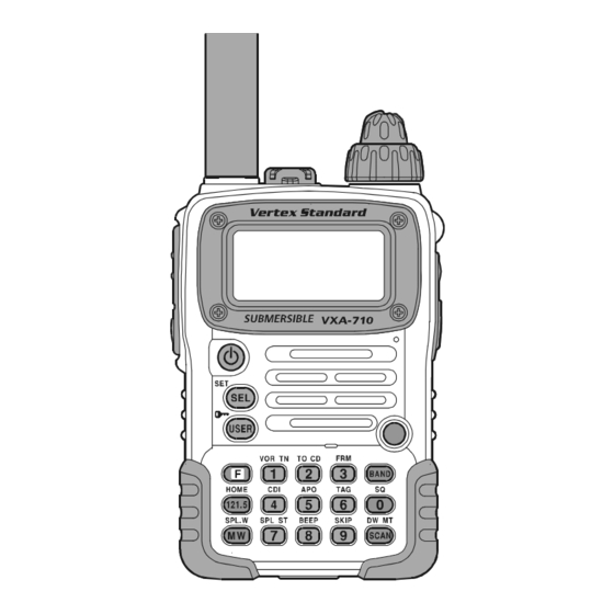
Page 6: Front Panel
& C ONTROLS ONNECTORS RONT ANEL LCD ( Liquid Crystal Display ) Microphone The display shows the current operating conditions, Speak across this opening in a normal voice level, while pressing the PTT switch, to transmit. including frequency, etc. PWR ( Power ) Switch Battery Pack Latch Press and hold this switch for 3 seconds to toggle the Open this latch for battery removal. -
Page 7: Side Panel
& C ONTROLS ONNECTORS ANEL PTT ( Push To Talk ) Switch Press this button to transmit when you are operating in the COM band (118.000 - 136.975 MHz). Release this button to return to the “Receive” mode. See page MONITOR Switch This button may be pressed to “Open”... -
Page 8: Keypad
& C ONTROL ONNECTORS EYPAD Primary Function Activates the “Secondary” key Frequency entry digit “1.” Frequency entry digit “2.” Press Key mode. Secondary Function None Activates VOR mode. Selects “TO” VOR mode. Press + Recalls Menu Item “SQL Type” Recalls Menu Item “TONE Set” Third Function None (for activating CTCSS or DCS decoder on... - Page 9 & C ONTROL ONNECTORS EYPAD Toggles the operating band Selects the tuning methods Primary Function Frequency entry digit “3.” between the AIR band and FM among the VFO, MR, BMR, WX, Press Key BC band in the VFO mode. and BRS Secondary Function Selects “FROM”...
-
Page 10: Before You Begin
EFORE EGIN How to Install the Quick Draw Belt Clip Precautions Connect the hanger to the rear of the VXA-710, with This apparatus is capable of two-way communication the notch pointing directly up, using the supplied screw on channels used for critical aviation safety commu- (Figure 1). -
Page 11: Installation Of Fnb-80Li Battery Pack
EFORE EGIN Installation of FNB-80LI Battery Pack Battery Charging The FNB-80LI is a high-performance Lithium-Ion bat- If the battery has never been used, or its charge is depleted, it may be charged by connecting the PA-48B/C Battery tery providing high capacity in a very compact package. Under normal use, the FNB-80LI may be used for ap- Charger, as shown in the illus- tration, to the EXT DC jack. -
Page 12: Installation Of Fba-23 Alkaline Battery Case
EFORE EGIN Installation of The FBA-23 does not provide connections for charging, FBA-23 Alkaline Battery Case ( Option ) since Alkaline cells cannot be re-charged. Therefore, the PA-48B/C, E-DC-5B, or E-DC-6 may safely be con- The optional FBA-23 Battery Case allows receive moni- nected to the EXT DC jack when the FBA-23 is installed. -
Page 13: Low Battery Indication
EFORE EGIN Low Battery Indication As you battery discharges during use, the voltage will gradually become lower. When the “ ” begins blinking on the LCD dis- play, the battery pack must be recharged before further use. Avoid recharging Li-Ion batteries before the “Low Bat- tery”... -
Page 14: Basic Operation
ASIC PERATION Preliminary Steps Operation Quick Start Install a charged battery pack onto the transceiver, as To turn the radio on, described previously. press and hold in the ( PWR ) Switch for 3 Screw the supplied antenna onto the Antenna jack. Never operate this transceiver without an antenna con- seconds. -
Page 15: Squelch Adjustment
ASIC PERATION To set 118.275 MHz, you do not need to press the and you may use this noise to set the VOL knob for the desired audio level. Press the MONITOR button final “5” in the frequency: momentarily to silence the noise and resume normal (quiet) monitoring. -
Page 16: Accessing The 121.5 Mhz Emergency Frequency
ASIC PERATION Accessing the 121.5 MHz Emergency Tuning Methods Frequency Throughout this manual, you will see references to sev- eral different frequency setting methods. Each will be par- The VXA-710 can quickly access the 121.500 MHz Emer- ticularly useful in a particular operating situation, and they gency Frequency. -
Page 17: Transmission
ASIC PERATION BOOK ( Pre-Programmed ) Memories Transmission The Book memories are To transmit, press and pre-programmed, either hold in the PTT switch. at the factory or by your Speak into the micro- Dealer (depending on phone area of the front your country’s requirements), typically including the panel grille in a normal major AIR band station frequencies used in your area... -
Page 18: Reception Of Weather Channel Broadcasts
ASIC PERATION Reception of Weather Channel Broadcasts If there are no Weather Channel Frequency ( USA version only ) Channels in your area, the WX 1 162.5500 MHz WX 2 162.4000 MHz scanner will not stop. The VXA-710 can receive VHF Weather Channel broad- WX 3 162.4750 MHz Press the MONITOR but-... -
Page 19: Monitor Key
ASIC PERATION ANL ( Automatic Noise Limiter ) Feature Monitor Key When listening to a very weak signal from an aircraft or For reduction of impulse noise, such as that produced by ground station, you may observe the signal disappearing an engine’s ignition system, the ANL feature may prove periodically as the incoming signal strength becomes too helpful. -
Page 20: Lock Function
ASIC PERATION LOCK Function Beep On/Off The lock function prevents accidental changes to the fre- The VXA-710’s key/button beeper provides convenient quency setting and the keypad controls. audible feedback whenever a button is pressed. Each key and button has a different beep pitch, and each function To activate the lock fea- has a unique beep combination. -
Page 21: Receive Battery Saver Setup
ASIC PERATION Receive Battery Saver Setup ABS: Automatic Battery Saver, based on activity on the receiver. An important feature of the VXA-710 is its Receive Bat- tery Saver, which “puts the radio to sleep” for a time inter- The setting of 1:5 will promote the greatest conservation val, periodically “waking it up”... -
Page 22: Memory Operation
EMORY PERATION The VXA-710 provides 70 user-programmable Main nel number for storage. In order to prevent writing memories, labeled “MR1” through “MR68”, “MRLch,” over memory channels, an “ ” icon will appear at and “MRUch,” up to 90 pre-programmed memories, des- the right of the channel number to indicate if the ignated “Book”... -
Page 23: Recalling The Memories
EMORY PERATION Recalling the Memories Memory Offset Tuning Press the key, repeatedly if necessary, until “MR” Once you have recalled a particular memory channel, you (Memory Recall) appears on the display. In the MR may easily tune off that channel, as though you were in the mode, you will see the previously-selected channel “VFO”... -
Page 24: Deleting Memories
EMORY PERATION Deleting Memories You may also attach an alpha/numeric name (label) to the “HOME” channel. With the VXA-710 in the Memory mode, rotate the DIAL selector knob to select the memory channel you Recall the “HOME” channel, by pressing the wish to delete. -
Page 25: Scanning Operation
CANNING PERATION Basic Scan ond after the signal disappears, after which scanning will resume. The VXA-710 allows you to scan automatically in the While the scanner remains paused on a frequency, the VFO* , Main Memory, “Book” Memory, Weather Chan- decimal point of the frequency display blinks. -
Page 26: Channel-Skip Scanning
CANNING PERATION Programmable ( Band Limit ) Memory Channel-Skip Scanning Scan ( PMS ) Continuous-carrier stations like ATIS (Automatic Termi- nal Information Service) or Weather Broadcast stations This feature allows you to set sub-band limits for either inhibit scanner operation. Since these stations are always scanning or manual VFO operation. -
Page 27: Dual Watch Operation
ATCH PERATION The Dual Watch feature automatically checks for activity While receiving on the priority channel, if you mo- mentarily press the PTT switch, Dual Watch will be on a “Priority” channel* while you are operating on an- other channel. During Dual Watch operation, the current disabled. -
Page 28: Priority Dual Watch Operation
RIORITY ATCH PERATION Similar to Dual Watch operation (described on previous To start Priority Dual page), Priority Dual Watch is an enhanced version which Watch, press the includes the following additional features: followed by the key. The “DW” icon will ap- The receiving time interval (ratio) between the cur- pear on the display. -
Page 29: Spectrum Scope Monitor
PECTRUM COPE ONITOR Once the Spectrum Scope Monitor is activated, press If you assign the Spectrum Scope Monitor feature to the key to change the visible bandwidth between key (see page 40), you may view operating activity ±15 channels and ±30 channels (default: ±30 chan- on channels above and below the current operating chan- nels). -
Page 30: Vor Navigation (Air Band)
VOR N AVIGATION General VOR Equipment COURSE Indicator COURSE Deviation Needle TWO-Degree Deviation Marks FROM “TO”-“FROM” Flag Indicator COM BAND NAV BAND 108.0000 - 117.9750 MHz 118.0000 - 136.9750 MHz VOR MODE CDI MODE COURSE Indicator COURSE Indicator COURSE Deviation Needle “TO”... -
Page 31: To Select The Vor Mode
VOR N AVIGATION To Select the VOR Mode COURSE Indicator When entering the NAV band (108.000 - 117.975 MHz), the VXA-710 selects the VOR mode automati- cally. The “Course Indicator” will appear on the dis- play, and the “TO” or “FROM” indicator will appear at the right of the “Course Indicator”... -
Page 32: Flying To A Vor Station
VOR N AVIGATION Flying to a VOR Station The Aircraft is “ON COURSE” The VXA-710 can indicate the deviation from the direct course to a VOR station. Select a VOR station on your aeronautical chart and turn the DIAL selector knob (or enter the frequency directly with the keypad) to the frequency of the VOR station. - Page 33 VOR N AVIGATION The Aircraft is “ON COURSE” VOR TAC Magnetic Los Angeles North LAX - 113.600MHz Station The Aircraft is “OFF COURSE” VOR TAC Magnetic Los Angeles North LAX - 113.600MHz Station VXA-710 S PIRIT PERATING ANUAL...
-
Page 34: Entering A Desired Course
VOR N AVIGATION Entering a Desired Course Note 2: If the overflow indicator “ ” appears on the right side, select a heading plus 10 degrees to the de- The VXA-710 can also be configured to indicate the de- sired course; if the overflow indicator “ ” appears viation from the desired course, not only the deviation from on the left side, select a heading minus 10 degrees. -
Page 35: Position Cross-Checking
VOR N AVIGATION Position Cross-checking Now set the frequency of the other VOR station in the VOR mode. Note the radial from the station you Select two VOR stations on your aeronautical chart. are on. Set the frequency of one of the VOR stations in the Extend the radials from each VOR station on the chart. -
Page 36: Split Operation
VOR N AVIGATION Split Operation Press and hold in the key for 2 seconds to save the transmit frequency and return to the NAV band The split operation feature allows you to transmit a call to frequency. a Flight Service Station using the COM band frequencies, Press and hold in the PTT switch to transmit on the while receiving a VOR station (in the NAV band). -
Page 37: Brs (Business Radio Service) Channel Operation
BRS ( B USINESS ADIO ERVICE HANNEL PERATION ters for information on how this may enhance opera- Recalling the BRS Channels tion. Press the key, re- To exit the BRS mode, press the key momen- peatedly if necessary, tarily to return to the VFO mode. until “BRS”... - Page 38 BRS ( B USINESS ADIO ERVICE HANNEL PERATION while operating in congested areas. The “ ” icon will appear Note: You may notice an additional “DCS” icon ap- at the bottom of the display pearing while you rotate the DIAL selector knob in when the CTCSS Decoder is this step.
-
Page 39: Dcs Operation
BRS ( B USINESS ADIO ERVICE HANNEL PERATION DCS Operation When you have made your selection, press the key to save the new setting, then press the PTT key Another form of tone access control is Digital Code repetitively until the radio exits to normal operation. Squelch, or DCS. -
Page 40: Ctcss/Dcs Bell Operation
BRS ( B USINESS ADIO ERVICE HANNEL PERATION CTCSS/DCS Bell Operation station calls you whose transceiver is sending a CTCSS tone or DCS code which matches that set into your de- During CTCSS Decoder or DCS Decoder operation, you coder, the “ ”... -
Page 41: Miscellaneous Setting
ISCELLANEOUS ETTINGS Automatic Power-Off ( APO ) Feature within the time interval pro- grammed, the microprocessor The APO feature helps conserve battery life by automati- will shut down the radio auto- cally turning the radio off after a user-defined period of matically. -
Page 42: Programming The Key Assignments
ISCELLANEOUS ETTINGS Menu Item. Rotate the DIAL selector knob to select Sub Menu Rotate the DIAL selector knob to set the Time-Out Item “3. USER 1” (for the “press key” function) or Timer to the desired “Maximum TX” time (1 minute, “4. -
Page 43: Display Customization
ISCELLANEOUS ETTINGS When you have made your selection, press the Display Dimmer key to save the new setting, then press the PTT key The LCD illumination may be adjusted using the Menu, repetitively until the radio exits to normal operation. as well. -
Page 44: Tx/Busy Indicator Customization
ISCELLANEOUS ETTINGS TX/BUSY Indicator Customization Press the key again, then rotate the DIAL selec- tor knob to adjust the “G” (green) element of the color. Default TX/BUSY illumination colors have been assigned Repeat the process described above to adjust the “B” at the factory. -
Page 45: Changing The Channel Step
ISCELLANEOUS ETTINGS Changing the Channel Steps The VXA-710 allows you to choose channel steps in the FM broadcast band: 5/10/12.5/15/20/25/50/100 kHz per step. The VXA-710 is set up at the factory to 100 kHz which probably is satisfactory for most operation. How- ever, if you need to change the channel step increments, the procedure to do so is very easy. -
Page 46: Field Programming Mode
IELD ROGRAMMING The VXA-710’s “Book” Memories also allow the user to exit. store, label, and recall channel frequencies which you may To label a memory with an alpha/numeric name, the want to use frequently by placing the VXA-710 into the next step is to use the DIAL selector knob to select “Field Programming mode.”... -
Page 47: Cpu Resetting
CPU R IELD ROGRAMMING ESETTING In some instances of erratic or unpredictable operation, Deleting Memories the cause may be corruption of data in the microproces- Press and hold in both the PTT switch and key, sor (due to static electricity, etc.). If this happens, reset- while turning the radio on, to activate the Field Pro- ting of the microprocessor may restore normal operation. -
Page 48: Timer Mode
( “S ” ) M IMER The VXA-710 provides both “STOP WATCH” and The Menu system allows certain aspects of your radio’s “COUNT DOWN” timers. These may be used for a vari- configuration to be customized for your personal operat- ety of time-keeping purposes. - Page 49 ( “S ” ) M MENU Listing A listing of the Menu items available via the SET mode may be found below. Available Values ( Default: Bold Itaric ) Set Mode Item Function 1. Display 1. Scan Lamp Enables/Disables the Scan lamp while paused during scanning. On / Off 2.
- Page 50 ( “S ” ) M 5. Dimmer 1. D ISPLAY Function: Setting of the display brightness level. 1. Scan Lamp Available Values: LV 1 - LV 4 Function: Enables/Disables the Scan lamp while paused Default Setting: LV 3 during scanning. 6.
- Page 51 ( “S ” ) M 8. RX LED 12. TEMP LED Function: Edits the BUSY indicator color. Function: Edits the Over Heating lamp color. This is a Available Values: Individual adjustments of the Red, display seen when the temperature exceeds the threshold Green, and Blue color hue may be performed, on a nu- set via the “TEMP Set”...
- Page 52 ( “S ” ) M 3. Power On Beep 4. DW/PRI Function: Selects the Power-on beep. Function: Selects the Dual Watch/Priority Function. Available Values: Off/Mode 1/Mode 2/Mode 3 Available Values: DW/PRI Default Setting: Mode 1 Default Setting: DW 5. RX Save 3.
- Page 53 ( “S ” ) M 7. PRI Time 11. DCS Set Function: Selects the Priority Checking Time. Function: Setting of the DCS Code. Available Values: 500ms/1s/1.5s/2s/2.5s/3s Available Values: 106 standard DCS codes. Default Setting: 2s Default Setting: 023 This Menu Item allows you to define how often the Prior- ity Channel will be checked for activity.
- Page 54 ( “S ” ) M 4. T 3. USER 1 RANSMIT Function: Programming the key assignment (momen- 1. T.O.T tary-press mode). Function: Setting of the Time-Out Timer Countdown Time. Available Values: ANL/XFER/SPEC Start/Large Font/ Available Values: Off/1min/3min/5min None Default Setting: Off Default Setting: ANL The Time-Out Timer shuts off the transceiver after con- See page 40 for details.
- Page 55 ( “S ” ) M 2. Emergency 4. TEMP Unit Function: Selects the Emergency feature. Function: Selects the measurement units for the Tempera- Available Values: 121.5/LED+121.5/LED ture sensor. Default Setting: LED+121.5 Available Values: °F/°C 121.5: Pressing the key momentarily accesses Default Setting: °F the 121.5 MHz Emergency Frequency.
- Page 56 ( “S ” ) M 7. Bandwidth 2. TEMP Offset Function: Selects the receiving bandwidth of the BRS Function: Correcting the Thermometer setting Memory Channel. Available Values: [–22.8 °F (–12.7 °C)] - [+22.8 °F (+12.7 Available Values: Wide (±25 kHz)/Narrow (±12.5 kHz) °C)] Default Setting: Wide (±25 kHz) Default Setting: 0.0 °F (0.0 °C)
- Page 57 VXA-710 S PIRIT PERATING ANUAL...
- Page 58 PECIFICATIONS General Frequency Range: 118.000 - 136.975 MHz (COM Band) 88.000 - 108.000MHz (FM BC Band), 108.000 - 117.975 MHz (NAV Band), 118.000 - 136.975 MHz (COM Band), 151.5125 - 158.400MHz (BRS Memory Channels), Weather Channel (WX-01 - WX-10) 25 kHz (AIR Band), Channel Spacing: 5/10/12.5/15/20/25/50/100 kHz (FM BC Band) Emission Type:...
-
Page 59: Specifications
PECIFICATIONS Receiver Circuit Type: Double-conversion Superheterodyne 35.4 MHz & 450 kHz ( AM / NFM ), IFs: 45.65 MHz & 10.7MHz ( WFM ) Sensitivity: 88-108 MHz: better than 2 µV (for 12 dB SINAD with 1 kHz tone @ 22.5 kHz deviation) 108 MHz-137 MHz: better than 1 µV (for 6 dB S/N with 1 kHz tone @ 30 % modulation) BRS-01 - BRS-21: better than 0.32 µV (for 12 dB S/N with 1 kHz tone @ 3.5 kHz deviation) WX-01 - WX-10: better than 0.4 µV (for 12 dB S/N with 1 kHz tone @ 3.5 kHz deviation) -
Page 60: Accessories & Options
& O CCESSORIES PTIONS Supplied Accessories Available Options LI-ion Battery Pack (7.4 V) FNB-80LI ......1 MH-44 Speaker Microphone Battery Charger PA-48B or PA-48C ......1 PA-48B/C Battery Charger Helical Antenna ATV-14 ..........1 FBA-23 Alkaline Battery Case Headset Cable CT-96 ............ 1 CD-15A Desktop Rapid Charger Operating Manual ............ - Page 61 & O CCESSORIES PTIONS External Antenna Headset PTT Switch (not supplied) (not supplied) An external PTT switch is required for use with an avia- tion headset. CT-96 Headset Cable CN-3 Antenna Adapter (Option) E-DC-5B External Power Cable (Option) VXA-710 S PIRIT PERATING ANUAL...
-
Page 62: Troubleshooting
ROUBLESHOOTING When connecting the CT-96 headset cable between This happens when the connector on the CT-96 headset cable is simply pushed into the MIC/EAR jack. the radio and a headset, the red transmit LED on The jack must be screwed into the MIC/EAR jack to make proper contacts the radio turns on and the radio cannot be operated. - Page 63 VXA-710 S PIRIT PERATING ANUAL...
-
Page 64: Book Memory Channel List
EMORY HANNEL IST USA V ERSION ACTORY EFAULT ( MH ( MH CH N CH N LPHA REQUENCY LPHA REQUENCY AIR-AIR 123.450 Unofficial Air-Air ARTCC 07 136.175 Air Traffic Control General Use AIR-AIR 131.800 Air to Air ARTCC 08 136.225 Air Traffic Control General Use ARINC 01 136.500... - Page 65 EMORY HANNEL IST EXP V ERSION ACTORY EFAULT CH N CH N LPHA REQUENCY LPHA REQUENCY AMS VMT 126.200 AMSTERDAM MET BROADCAST WAW VMT 127.600 WARSAW VOLMET ANK VMT 127.000 ANKARA (ESENBOGA MET BROADCAST) ZRH VMT 127.200 ZURICH MET ATH VMT 127.800 ATHENS(ATHINAI VOLMET) AMS ATIS...
- Page 66 VXA-710 S PIRIT PERATING ANUAL...
- Page 67 Part 15.21: Changes or modifications to this device not expressly approved by YAESU MUSEN could void the user’s authorization to operate this device.
- Page 68 Copyright 2012 YAESU MUSEN CO., LTD. YAESU MUSEN CO., LTD. Tennozu Parkside Building 2-5-8 Higashi-Shinagawa, Shinagawa-ku, Tokyo 140-0002 Japan All rights reserved. YAESU USA 6125 Phyllis Drive, Cypress, CA 90630, U.S.A. No portion of this manual may be YAESU UK LTD. reproduced without the permission of Unit 12, Sun Valley Business Park, Winnall Close Winchester, Hampshire, SO23 0LB, U.K.
Need help?
Do you have a question about the VXA-710 Spirit and is the answer not in the manual?
Questions and answers